1
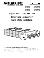
IC525A-F
IC525A-M
IC526A-F
IC526A-M
NOVEMBER 1999
IC525AE-F
IC525AE-M
IC526AE-F
IC526AE-M
Async RS-232 to RS-485
Interface Converter
with Opto Isolation
CUSTOMER SUPPORT INFORMATION
Order toll-free in the U.S. 24 hours, 7 A.M. Monday to midnight Friday: 877-877-BBOX
FREE technical support, 24 hours a day, 7 days a week: Call 724-746-5500 or fax 724-746-0746
Mail order: Black Box Corporation, 1000 Park Drive, Lawrence, PA 15055-1018
Web site: www.blackbox.com • E-mail: [email protected]
RS-232 TO RS-485 INTERFACE CONVERTER W/OPTO ISOLATION
FEDERAL COMMUNICATIONS COMMISSION
AND
CANADIAN DEPARTMENT OF COMMUNICATIONS
RADIO FREQUENCY INTERFERENCE STATEMENTS
This equipment generates, uses, and can radiate radio frequency energy and if
not installed and used properly, that is, in strict accordance with the
manufacturer’s instructions, may cause interference to radio communication. It
has been tested and found to comply with the limits for a Class A computing
device in accordance with the specifications in Subpart J of Part 15 of FCC rules,
which are designed to provide reasonable protection against such interference
when the equipment is operated in a commercial environment. Operation of
this equipment in a residential area is likely to cause interference, in which case
the user at his own expense will be required to take whatever measures may be
necessary to correct the interference.
Changes or modifications not expressly approved by the party responsible for
compliance could void the user’s authority to operate the equipment.
This digital apparatus does not exceed the Class A limits for radio noise emission from
digital apparatus set out in the Radio Interference Regulation of Industry Canada.
Le présent appareil numérique n’émet pas de bruits radioélectriques dépassant les limites
applicables aux appareils numériques de classe A prescrites dans le Règlement sur le
brouillage radioélectrique publié par Industrie Canada.
The CE symbol on your equipment indicates that it complies with the
Electromagnetic Compatibility (EMC) directive and Low Voltage Directive
(LVD) of the Union European (EU).
1
RS-232 TO RS-485 INTERFACE CONVERTER W/OPTO ISOLATION
NORMAS OFICIALES MEXICANAS (NOM)
ELECTRICAL SAFETY STATEMENT
INSTRUCCIONES DE SEGURIDAD
1. Todas las instrucciones de seguridad y operación deberán ser leídas antes
de que el aparato eléctrico sea operado.
2. Las instrucciones de seguridad y operación deberán ser guardadas para
referencia futura.
3. Todas las advertencias en el aparato eléctrico y en sus instrucciones de
operación deben ser respetadas.
4. Todas las instrucciones de operación y uso deben ser seguidas.
5. El aparato eléctrico no deberá ser usado cerca del agua—por ejemplo,
cerca de la tina de baño, lavabo, sótano mojado o cerca de una alberca,
etc..
6. El aparato eléctrico debe ser usado únicamente con carritos o pedestales
que sean recomendados por el fabricante.
7. El aparato eléctrico debe ser montado a la pared o al techo sólo como sea
recomendado por el fabricante.
8. Servicio—El usuario no debe intentar dar servicio al equipo eléctrico más
allá a lo descrito en las instrucciones de operación. Todo otro servicio
deberá ser referido a personal de servicio calificado.
9. El aparato eléctrico debe ser situado de tal manera que su posición no
interfiera su uso. La colocación del aparato eléctrico sobre una cama,
sofá, alfombra o superficie similar puede bloquea la ventilación, no se
debe colocar en libreros o gabinetes que impidan el flujo de aire por los
orificios de ventilación.
2
NOM STATEMENT
10. El equipo eléctrico deber ser situado fuera del alcance de fuentes de calor
como radiadores, registros de calor, estufas u otros aparatos (incluyendo
amplificadores) que producen calor.
11. El aparato eléctrico deberá ser connectado a una fuente de poder sólo del
tipo descrito en el instructivo de operación, o como se indique en el
aparato.
12. Precaución debe ser tomada de tal manera que la tierra fisica y la
polarización del equipo no sea eliminada.
13. Los cables de la fuente de poder deben ser guiados de tal manera que no
sean pisados ni pellizcados por objetos colocados sobre o contra ellos,
poniendo particular atención a los contactos y receptáculos donde salen
del aparato.
14. El equipo eléctrico debe ser limpiado únicamente de acuerdo a las
recomendaciones del fabricante.
15. En caso de existir, una antena externa deberá ser localizada lejos de las
lineas de energia.
16. El cable de corriente deberá ser desconectado del cuando el equipo no
sea usado por un largo periodo de tiempo.
17. Cuidado debe ser tomado de tal manera que objectos liquidos no sean
derramados sobre la cubierta u orificios de ventilación.
18. Servicio por personal calificado deberá ser provisto cuando:
A:
El cable de poder o el contacto ha sido dañado; u
B:
Objectos han caído o líquido ha sido derramado dentro del
aparato; o
C:
El aparato ha sido expuesto a la lluvia; o
D:
El aparato parece no operar normalmente o muestra un cambio en
su desempeño; o
E:
El aparato ha sido tirado o su cubierta ha sido dañada.
3
RS-232 TO RS-485 INTERFACE CONVERTER W/OPTO ISOLATION
TRADEMARKS
The trademarks mentioned in this manual are the sole
property of their owners.
4
CONTENTS
CONTENTS
1. Specifications . . . . . . . . . . . . . . . . . . . . . . . . . . . 6
2. Introduction. . . . . . . . . . . . . . . . . . . . . . . . . . . . 8
2.1 Description. . . . . . . . . . . . . . . . . . . . . . . . . . 8
2.2 Features . . . . . . . . . . . . . . . . . . . . . . . . . . . . 8
3. Configuration . . . . . . . . . . . . . . . . . . . . . . . . . . 10
3.1 DIP Switches. . . . . . . . . . . . . . . . . . . . . . . . . 10
3.2 Jumpers. . . . . . . . . . . . . . . . . . . . . . . . . . . . . 14
4. Installation . . . . . . . . . . . . . . . . . . . . . . . . . . . . . 15
4.1 Connection to the RS-485 Interface. . . . . . 15
4.1.1 4-Wire Connection Using RJ-45 . . . . . . 15
4.1.2 2-Wire Connection Using RJ-45 . . . . . . 17
4.1.3 4-Wire Connection Using Terminal
Blocks . . . . . . . . . . . . . . . . . . . . . . . . . . 17
4.1.4 2-Wire Connection Using Terminal
Blocks . . . . . . . . . . . . . . . . . . . . . . . . . . 20
4.2 Daisychain Topology . . . . . . . . . . . . . . . . . . 20
4.3 Connection to the RS-232 Interface. . . . . . 21
4.4 Operating the Converter. . . . . . . . . . . . . . . 22
Appendix: RS-232 Pin Configurations . . . . . . . . . 23
5
RS-232 TO RS-485 INTERFACE CONVERTER W/OPTO ISOLATION
1. Specifications
Distance—Up to 4000 ft. (1219.2 m)
Interface—RS-232 is DCE
Operation—4-wire full- or half-duplex,
2-wire half-duplex
Speed—Up to 115.2 kbps
Transmission Format—Asynchronous
Optical Isolation—2500 Vrms
RS-232 Interface—DB25, female
RS-422/485 Interface Options—RJ-45 or terminal
block
Connectors—IC525A-F: (1) DB25 female,
(1) terminal block with strain relief; IC525A-M:
(1) DB25 male, (1) terminal block with strain
relief; IC526A-F: (1) DB25 female, (1) RJ-45;
IC526A-M: (1) DB25 male, (1) RJ-45
Temperature—32 to 122 °F (0 to 50 °C)
Humidity—5 to 95%, non-condensing
6
CHAPTER 1. Specifications
Power—External power adapter, 5-VDC, 300 mA;
“AE” models accept 220-volt input power
Size—0.8"H x 2.1"W x 3.8"D (2 x 5.3 x 9.7 cm)
7
RS-232 TO RS-485 INTERFACE CONVERTER W/OPTO ISOLATION
2. Introduction
2.1 Description
The Async RS-232 to RS-485 Interface Converter with
Opto Isolation provides exceptional versatility in a
compact package. The Converter comes with an
external AC power adapter and supports asynchronous
RS-232 data rates up to 115.2 kbps over one or two
unconditioned twisted pairs.
The Converter can handle up to 32 terminal drops in
a multipoint polling environment. You can set carrier to
“constantly on,” “controlled by RTS,” or “controlled by
DTR,” and the unit operates without echo.
The Converter uses a male or female DB25 connector
for the RS-232 connection. Options for twisted pair
include RJ-11, RJ-45 or terminal block connectors.
2500-Vrms optical isolators provide isolation between
the RS-232 and RS-485 interfaces.
2.2 Features
• Operates asynchronously, point-to-point or
multipoint, over 2 or 4 wires.
8
CHAPTER 2. Introduction
• Up to 32 multipoint device drops in a polling
environment.
• Data rates to 115.2 kbps.
• Passes transmit and receive data.
• Operates via 5 V power supply.
• Operates without “echo.”
• Driver controlled as “constantly on,” “controlled
by RTS,” or “controlled by DTR.”
• Compact size: 0.8"H x 2.1"W x 3.8"D (2 x 5.3 x
9.7 cm)
• Twisted pair connection via strain relief, RJ-11, or
RJ-45.
• 2500 Vrms optical isolation.
9
RS-232 TO RS-485 INTERFACE CONVERTER W/OPTO ISOLATION
3. Configuration
You can configure the Converter via a four-position DIP
switch and two jumpers. Figure 3-1 shows the location of
the DIP switch and the two headers on the board.
JP4
DIP Switch
ON
ON
AA
BB
OFF
OFF
1 2 3 4
AA
BB
Power
JP3
Figure 3-1. Location of the DIP Switch and Jumpers.
3.1 DIP Switches
The DIP switches control the transmit/receive signals on
the Converter. Table 3-1 shows the default configuration
of the switches. Table 3-2 shows the different switch and
jumper combinations for the Converter. Also included
in this section is a description of the switches.
10
CHAPTER 3. Configuration
Table 3-1. DIP Switch Default Settings.
Position
S1
S2
S3
S4
Function
RTS Control
DTR Control
Reserved
Transmitter Control
Switch
OFF
OFF
OFF
ON
Function
No RTS control of transmitter
No DTR control
N/A
Constantly ON
Table 3-2. Switch Combinations (NOTE: JP4B is N/A).
S1-1†
RTS
Control
S1-2†
DTR
Control
S1-3
Always
OFF
Reserved
RS-485, full-duplex OFF
Transmitter is ON.
OFF
S1-4†
RS-485
TX
Always
ON
ON
JP4A* JP3A and
JP3B**
OFF
Both OFF.
RS-485, full-duplex ON
Transmitter is
controlled by RTS.
OFF
OFF
OFF
Both OFF.
RS-485, full-duplex OFF
Transmitter is
controlled by DTR.
ON
OFF
OFF
Both OFF.
Half-duplex, 4-wire ON
controlled by RTS.
OFF
OFF
ON
Both OFF.
Half-duplex, 2-wire ON
controlled by RTS.
OFF
OFF
ON
Both ON.
Half-duplex, 4-wire OFF
controlled by DTR.
ON
OFF
ON
Both OFF.
Half-duplex, 2-wire OFF
controlled by DTR.
ON
OFF
ON
Both ON.
11
RS-232 TO RS-485 INTERFACE CONVERTER W/OPTO ISOLATION
KEY TO TABLE 3-2
†S1-1, S1-2, and S1-4: only one switch can be ON at any time. The other
two must be OFF. We recommend that you disconnect the Converter while
changing configurations.
*JP4A: If this jumper is off, only the RS-485 transmitter is controlled by
RTS or DTR. If this jumper is ON, both the RS-485 transmitter and receiver
are controller by RTS or DTR. When the transmitter is OFF, the receiver will
be ON, and similarly, when the transmitter is ON, the receiver is OFF.
**JP3A and JP3B: Both jumpers are either ON or OFF. When the jumpers
are ON, the RS-485 transmitter and receiver are connected directly
together. This will only function in half-duplex mode. When both jumpers
are OFF, the RS-485 transmitter and receiver are disconnected from each
other. The Converter can operate in either half- or full-duplex, depending on
the setting of JP4A.
SWITCH S1: RTS CONTROL
When Switch S1 is in the ON position, the DTE input
signal RTS (Pin 4) controls the transmitter of the
Converter. In this mode, when RTS is high, the
Converter transmits data from the RS-232 port to the
RS-485 port. Switch S2 and S4 must be in the OFF
position when Switch S1 is ON.
S1
ON
OFF
12
Setting
RTS controls the transmitter
RTS control is OFF
CHAPTER 3. Configuration
SWITCH S2: DTR CONTROL
When Switch S2 is in the ON position, the DTE input
signal DTR (Pin 20) controls the transmitter of the
Converter. In this mode, when DTR is high, the
Converter transmits data from the RS-232 port to the
RS-485 port.
NOTE
Switches S1 and S4 must be OFF when Switch S2 is ON.
S2
ON
OFF
Setting
DTR controls the transmitter
DTR control is OFF
SWITCH S3: RESERVED
Switch S3 is reserved for future use and must remain
OFF.
SWITCH S4: TRANSMITTER CONTROL
When Switch S4 is OFF, the input of RTS or DTR
controls whether the unit can send data (based on the
configuration of Switches S1 and S2). In this setting, and
when the appropriate signal is high, the Converter can
transmit data from the RS-232 port to the RS-485 port.
When S4 is ON, the Converter’s transmitter is always
enabled.
13
RS-232 TO RS-485 INTERFACE CONVERTER W/OPTO ISOLATION
S4
ON
OFF
Setting
Constant Transmitter
Transmitter is controlled by RTS or DTR
3.2 Jumpers
Jumper straps JP3 and JP4 control two-wire/four-wire
and half-duplex/full-duplex operation, respectively.
Table 3-3. Interface Card Strap Summary.
Strap
JP3A
JP3B
JP4A
JP4B
Function
2-wire/4-wire mode
2-wire/4-wire mode
half- or full- duplex
Impedance
*Default settings.
14
ON
2-wire
2-wire
Half-duplex
120 ohms
(terminate)
OFF
4-wire*
4-wire*
Full-duplex*
12K ohms*
(unterminate)
CHAPTER 4. Installation
4. Installation
Once you have properly set the configuration switches
and jumpers, you are ready to connect the Converter to
your system. This section explains how to properly
connect the Converter to the RS-485 and RS-232
interfaces, and how to operate the Converter.
4.1 Connection to the RS-485 Interface
To function properly, the Converter must have one or
two twisted pairs of metallic wire. These pairs should be
“dry” (unconditioned) metallic wire, 24 AWG. We
recommend using Category 5 cable.
For your convenience, the Converter is available with
either a terminal block or an RJ-45 jack.
4.1.1 4-WIRE CONNECTION USING RJ-45
The RJ-45 connectors on the Converter’s RS-485 side are
pre-wired for a standard telco wiring environment. The
signal/pin relationships are shown in Table 4-1.
15
RS-232 TO RS-485 INTERFACE CONVERTER W/OPTO ISOLATION
Table 4-1. RJ-45 Signal/Pin Relationships.
RJ-45
1
2
3
4
5
6
7
8
Signal
- - - - - - - - - - - - - - - - - - - - - - - - - - - - - N/C
- - - - - - - - - - - - - - - - - - - - - - - - - - - - - GND*
- - - - - - - - - - - - - - - - - - - - - - - - - - - - - RCV- - - - - - - - - - - - - - - - - - - - - - - - - - - - - XMT+
- - - - - - - - - - - - - - - - - - - - - - - - - - - - - XMT- - - - - - - - - - - - - - - - - - - - - - - - - - - - - RCV+
- - - - - - - - - - - - - - - - - - - - - - - - - - - - - GND*
- - - - - - - - - - - - - - - - - - - - - - - - - - - - - N/C
*Connection to ground is optional.
1
1
Figure 4-1. RJ-45 Connector Pin Orientation.
In most modular RS-485 applications, you’ll need to
use a crossover cable.
16
CHAPTER 4. Installation
4.1.2 2-WIRE CONNECTION
Most RS-485 devices use a two-wire, half-duplex
configuration. When using this configuration, first set
the Converter to “two-wire” mode—then use only the
transmit (XMT) pair, as shown in Figure 4-2.
Converter Signal
RS-485 Signal
XMT+ - - - - - - - - - - - - - - - - - - >XMT-A
XMT- - - - - - - - - - - - - - - - - - - >XMT-B
Figure 4-2. Crossover cable wiring.
4.1.3 4-WIRE CONNECTION USING TERMINAL BLOCKS
If you purchased the IC525A-F or IC525A-M, you will
need to open the case to access the terminal blocks.
The following instructions will tell you how to open the
case, connect the bare wires to the terminal blocks, and
fasten the strain-relief collar in place so that the wires
won’t pull loose.
1. If the case is not already open, open it now by
twisting it open with a small plastic screwdriver.
2. Strip the outer insulation from the twisted pairs
about one inch from the end as shown in Figure
4-3.
17
RS-232 TO RS-485 INTERFACE CONVERTER W/OPTO ISOLATION
Figure 4-3. Stripping the Outer Insulation from the Twisted Pairs.
3. Strip back the insulation on each of the 2 twisted
pair wires about 1⁄4 inch as shown in Figure 4-4.
Figure 4-4. Stripping the Insulation on the 2 Twisted Pairs.
4. Place the cable through the end plate, and make a
small loop in the cable and feed the cable under
the tie wrap which is currently installed in the
board. When you have completed this assembly, it
should resemble the diagram shown in Figure 4-5.
Connect one pair of wires to XMT+ and XMT(transmit positive and negative) on the terminal
block, making careful note of which color is
positive, and which color is negative.
18
CHAPTER 4. Installation
Figure 4-5. Completed Strain-Relief Assembly.
5. Connect the other pair of wires to RCV+ and RCV(receive positive and negative) on both of the
terminal blocks, again making careful note of
which color is positive, and which is negative.
Ultimately, you will want to construct a two-pair crossover cable that makes a connection with the RS-422/485
device, as shown below.
IC525A/6A
Signal
XMT+
XMTRCV+
RCV-
Terminal Block
TB (5)
TB (4)
TB (1)
TB (2)
RS-422/485 Device
Signal
RCV+
RCVXMT+
XMT-
19
RS-232 TO RS-485 INTERFACE CONVERTER W/OPTO ISOLATION
4.1.4 2-WIRE CONNECTION USING TERMINAL BLOCKS
Most RS-485 devices employ a two-wire, half-duplex
configuration. When using this configuration, be sure
to first set the IC525A-F or IC525A-M to half-duplex
mode by switching DIP switches and jumpers (refer to
Chapter 3 for this configuration)—then use only the
transmit (XMT) pair, as shown below.
Converter Signal
RS-485 Signal
XMT+ - - - - - - - - - - - - - - - - - - +
XMT- - - - - - - - - - - - - - - - - - - -
4.2 Daisychain Topology
The Converter supports multipoint applications using a
daisychain topology.
Using a daisychain topology, you can connect several
Converters together in a master/slave arrangement.
Maximum distance between the units will vary based
upon the number of drops, data rate, wire gauge, etc.
Figure 4-6 shows how to wire the two-pair cables
properly for a Converter daisychain topology.
20
CHAPTER 4. Installation
NOTE
The ground connection is not needed.
Host
First Slave
Other Slave(s)
XMT+ - - - - - - - - - - - - - - - RCV+ - - - - - - - - - - - - - - - RCV+
XMT- - - - - - - - - - - - - - - - - RCV- - - - - - - - - - - - - - - - - RCVRCV+ - - - - - - - - - - - - - - - XMT+ - - - - - - - - - - - - - - - XMT+
RCV- - - - - - - - - - - - - - - - - XMT- - - - - - - - - - - - - - - - - XMT-
Figure 4-6. Daisychain Wiring for Converter Host and Slaves.
NOTE
This unit can be configured for line termination. If
termination is required, a resistor will have to be externally
connected.
4.3 Connection to the RS-232 Interface
Once you have properly configured the Converter and
connected the twisted-pair wires correctly, simply plug
the Converter directly into the DB25 port of the RS-232
DTE device. Remember to insert and tighten the two
captive connector screws.
NOTE
If you must use a cable to connect the Converter to the
RS-232 device, make sure it is a straight-through cable of
the shortest possible length—we recommend 6-ft. (1.8-m)
or less. If you are connecting it to a DCE device (such as a
modem or a mux), a cross-over (null modem) cable is
required. See Appendix A for pinning of a null modem
cable.
21
RS-232 TO RS-485 INTERFACE CONVERTER W/OPTO ISOLATION
4.4 Operating the Converter
Once the Converter is properly installed, it should
operate transparently—as if it were a standard cable
connection. Operating power is derived from the RS-232
data and control signals; there is no “ON/OFF” switch.
22
APPENDIX
Appendix: Pin Configurations
Direction
“DCE Female” Setting
—
Data Terminal Ready (DTR) 20
To Converter
Direction
—8 (DCD) Data Carrier Detect From Converter
—7 (SG) Signal Ground
—6 (DSR) Data Set Ready
—5 (CTS) Clear to Send
—4 (RTS) Request to Send
—3 (RD) Receive Data
—2 (TD) Transmit Data
—1 (FG) Frame Ground
Figure A-1. RS-232 Pin Configuration.
[
2 -------------------------3
3 -------------------------2
4 -------------------------5
5 -------------------------4
6
8 - - - - - - - - - - - - - - - - - - - - - - - - - 20
20 - - - - - - - - - - - - - - - - - - - - - - - - 6
8]
7 -------------------------7
Figure A-2. Null Modem Pinning.
23
RS-232 TO RS-485 INTERFACE CONVERTER W/OPTO ISOLATION
RJ-45
Signal
1 - - - - - - - - - - - - - - - - - - - - - - - - - N/C
2 - - - - - - - - - - - - - - - - - - - - - - - - - GND*
3 - - - - - - - - - - - - - - - - - - - - - - - - - RCV4 - - - - - - - - - - - - - - - - - - - - - - - - - XMT+
5 - - - - - - - - - - - - - - - - - - - - - - - - - XMT6 - - - - - - - - - - - - - - - - - - - - - - - - - RCV+
7 - - - - - - - - - - - - - - - - - - - - - - - - - GND*
8 - - - - - - - - - - - - - - - - - - - - - - - - - N/C
*Connection to ground is optional
1
1
Figure A-2. RS-485 Pin Orientation.
24
© Copyright 1999. Black Box Corporation. All rights reserved.
1000 Park Drive • Lawrence, PA 15055-1018 • 724-746-5500 • Fax 724-746-0746