1
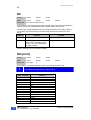
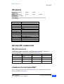
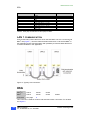
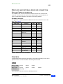
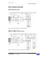
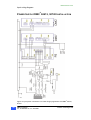
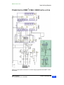
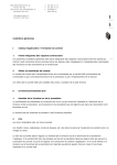
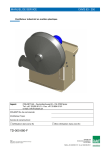
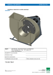
HEAD OFFICE
INMOTION TECHNOLOGIES AB
Solkraftsvägen 13
SE-135 70 Stockholm
SWEDEN
Telephone: +46 (0)8 682 64 00
Telefax: +46 (0)8 682 65 80
[email protected]
http://www.inmotech.com
DMC2
Digital Motion Controller
APPLICATIONS CENTERS
GREAT BRITAIN
SWEDEN
Inmotion Technologies
/Danaher Motion
Bridge Mills
Holmfirth
Huddersfield
HD9 3TW
Telephone: +44 (0)1484 68 83 25
Telefax: +44 (0)1484 68 83 26
Inmotion Technologies AB
Solkraftsvägen 13
SE-135 70 Stockholm
Telephone: +46 (0)8 682 64 00
Telefax: +46 (0)8 682 65 80
GERMANY
ACC Motion GmbH
Zähringerstrasse 23
DE-77654 Offenburg
Telephone: +49 (0)781 919 08-0
Telefax: +49 (0)781 919 08-29
ITALY
ACC Motion Srl
c/o Fluke Slr
Viale delle Industrie 11
IT-20090 Vimodrone (MI)
Telephone: +39 02 25 00 161
Telefax: +39 02 25 00 450
DMC2 Connection
Inmotion Technologies AB
Box 195
SE-234 23 Lomma
Telephone: +46 (0)40 41 48 50
Telefax: +46 (0)40 41 48 55
SWITZERLAND
ACC Motion SA
Wehntalerstrasse 6
CH-8154 Oberglatt
Telephone: +41 (0)1 851 5010
Telefax: +41 (0)1 851 5020
ACC Motion SA
La Pierreire
CH-1029 Villars-Ste-Croix
Telephone: +41 (0)21 863 6464
Telefax: +41 (0)21 863 6479
Art.No. 9032 0027 11
U.S.A.
Inmotion Technologies
211 Overlock Drive
Sewickley, PA 15143-2305
Telephone: +1 (412) 749 0710
Telefax: +1 (412) 749 0705
21.03.2001
Inmotion Technologies AB
Stockholm, Sweden
© Inmotion Technologies AB, 2001.
All rights reserved.
2
DMC2 Connection
Doc. No.9032 0027 11 Rev. 21.03.2001
Inmotion Technologies AB
Table of Contents
Table of Contents...............................................................................3
DMC2 Connections.............................................................................5
General ..................................................................................................................5
X Connector’s ........................................................................................................6
DSUB Connector’s .............................................................................................6
2
DMC Front ............................................................................................................7
2
DMC I/O Connections...........................................................................................8
2
2
DMC 50412/P, DMC 50720/P .............................................................................9
2
2
DMC 51540/P, DMC 53080 ..............................................................................10
Power Supply 580160..........................................................................................11
X1.........................................................................................................................11
X2.........................................................................................................................12
X4 (host) ..............................................................................................................12
X5 (next) ..............................................................................................................13
X4 and X5 connection..........................................................................................13
RS 232 Interface ..............................................................................................13
2
Communication between DMC .......................................................................13
LAN 1 communication ......................................................................................14
X6A ......................................................................................................................14
Resolver and external resolver connection ......................................................15
Resolver Connection from motor ..................................................................15
External resolver ...........................................................................................15
Syncbox............................................................................................................15
X6B ......................................................................................................................15
X7A/B ...................................................................................................................16
Pinouts user I/O................................................................................................17
X8A ......................................................................................................................17
X9A ......................................................................................................................18
X10.......................................................................................................................18
X11.......................................................................................................................19
X13.......................................................................................................................19
X14.......................................................................................................................20
X20.......................................................................................................................20
X21.......................................................................................................................20
X22.......................................................................................................................21
X23.......................................................................................................................21
X31.......................................................................................................................22
X32 & X33 ............................................................................................................22
2
2
DMC 50412 or DMC 50720 DC Bus Connection ..........................................22
2
2
DMC 51540 or DMC 53080 DC Bus Connection ..........................................23
X34.......................................................................................................................23
X35.......................................................................................................................24
Input wiring diagram.............................................................................................25
Single Installation .............................................................................................25
2
2
DMC -P/ DMC Installation...............................................................................25
2
Power Supply/DMC 50412, 50720 Installation ...............................................26
2
Power Supply/DMC 51540, 53080 Installation ...............................................27
DMC2 Connection
Doc. No.9032 0027 11, Rev. 21.03.2001
Inmotion Technologies AB
3
2
DMC Connections
GENERAL
2
This section provides details for connecting the DMC to motor connections, power,
dynamic brake, thermistor /brake, DC Bus, I/O, Daisy chain, LAN 2 and integral
resolver.
The motor cable connector nomenclature and location is different
2
for the various DMC models.
WARNING
♦
♦
♦
♦
♦
♦
Failure in properly ground this equipment could result is
serious or fatal injury to personnel who come into contact
with the equipment. All earth grounds must be installed per
the instructions in this chapter, and the equipment must be
securely connected to a quality earth ground before power is
applied for the first time. In addition, the panel or enclosure
housing the equipment must be securely earth grounded.
Local regulations may require additional grounding measures
beyond those shown in this chapter.
Failure to properly ground the equipment may result in
damage to the equipment or damage to other devices
connected to the equipment.
WARNING
This equipment uses high voltages, which can cause serious
or fatal electrical shock.
Can cause serious or fatal injury.
Only qualified personnel should perform installation and
wiring.
DMC2 Connection
Doc. No.9032 0027 11, Rev. 21.03.2001
Inmotion Technologies AB
5
DMC2 CONNECTIONS
X Connector’s
X CONNECTOR’S
Connector
Function
Interface
Page
X1
Input power
11
X2
+ 24 V External DC
12
X4
Host
RS 232, RS 422, LAN 1, X5
12
X5
Next
RS 232, RS 422, LAN 1, X4
13
X6A
Resolver, Feedback
X6B
Optional.Position.Sensor
14
Available only for DMC2 CAN
15
X7A
I/O
16
X7B
I/O
16
X8A
Measure connection
Available only for DMC2 CAN
17
X9
LAN2
Available only for DMC2 CAN
18
X10
DC Bus
X10P, X32, X33
18
X11
Motor
X13
Dynamic brake
X34
19
X14
Thermistor/brake
X35
20
X20
DC Bus
X20P, X32, X33
20
X21
Motor
X22
Dynamic brake
X34
21
X23
Thermistor/brake
X35
21
X31
Input power
X32
DC Bus
X10, X20
22
X33
DC Bus
X10, X20
22
X34
Dynamic brake
X13, X22
23
X35
Thermistor/brake
Temperature switch
X14, X23
24
19
20
22
DSUB CONNECTOR’S
Connector
6
D-Sub miniature in Metal housing
Pin
Male
Female
X4 and X5
High Density, VGA
15
X
X6A
Standard
15
X
X6B
Standard
25
X
X8A
Standard
9
X
X9
Standard
9
X
DMC2 Connection
Doc. No.9032 0027 11, Rev. 21.03.2001
Inmotion Technologies AB
DMC2 CONNECTIONS
DMC2 Front
DMC2 FRONT
2
Figure 1. DMC Front and Connections.
DMC2 Connection
Doc. No.9032 0027 11, Rev. 21.03.2001
Inmotion Technologies AB
7
DMC2 CONNECTIONS
DMC2 I/O Connections
DMC2 I/O CONNECTIONS
2
Figure 2. I/O Connections for all DMC units, bottom view.
8
DMC2 Connection
Doc. No.9032 0027 11, Rev. 21.03.2001
Inmotion Technologies AB
DMC2 CONNECTIONS
DMC2 50412/P, DMC2 50720/P
DMC2 50412/P, DMC2 50720/P
2
Figure 3. DMC unit connectors on the topside, Motor, Power, Thermistor, DC Bus
for 50412/P and 50720/P.
DMC2 Connection
Doc. No.9032 0027 11, Rev. 21.03.2001
Inmotion Technologies AB
9
DMC2 CONNECTIONS
DMC2 51540/P, DMC2 53080
DMC2 51540/P, DMC2 53080
2
Figure 4. DMC unit connectors on the topside, Motor, Power, Thermistor, DC Bus
for 51540/P and 53080.
10
DMC2 Connection
Doc. No.9032 0027 11, Rev. 21.03.2001
Inmotion Technologies AB
DMC2 CONNECTIONS
Power Supply 580160
POWER SUPPLY 580160
Figure 5. PS 580160 unit connectors on top side, Power, Dynamic brake and
Thermistor.
X1
2
50412
50720
51540
2
50412
50720
51540
DMC P
DMC
Connector
53080
See User’s Manual part A.
2
Input power is connected to X1 Figure 3 or Figure 4 on top of the DMC unit as
shown in Figure 7 for a Single and Figure 8 for a Master/Follower application.
2
Connect DMC 5xxxxP models to 400 VAC mains.
2
DMC X1
Function
1
PE
2
Phase L1
3
Phase L2
4
Phase L3
2
Table 1. Connection Mains to DMC .
DMC2 Connection
Doc. No.9032 0027 11, Rev. 21.03.2001
Inmotion Technologies AB
11
DMC2 CONNECTIONS
X2
X2
2
50412
50720
51540
2
50412
50720
51540
DMC P
DMC
Connector
53080
See User’s Manual part A.
Connections for 24V external logic supply voltage. When connected, it supplies the
internal control circuit, feedback sensors, communication and I/O ports.
The 24V logic supply shall always be connected before the main supply voltage is
connected to the input power port. External fuse shall be used rated max 1.5A T
(slow).
2
DMC X2
Function
Remark
1
0 V Supply
Internal connected to X7A,pin 5
2
+ 24 V Supply,
+20%: -20%, maximum supply
current 0.7A (not including load
on digital outputs)
Internal connected to X7B, pin 25
2
Table 2. External +24 V Connection to DMC .
X4 (HOST)
2
50412
50720
51540
2
50412
50720
51540
See page
6
DMC P
DMC
Connector
53080
2
X4 is used for connections between external PC and other DMC units.
i
The maximum length for this cable is 15 m.
2
DMC X4 (Host)
1
2
3
4
5
6
7
8
9
10
11
12
13
14
15
12
Function
Shield
RX
TX
Sync+
SyncNC
GND
+15 V
Daisy Chain, RX
Daisy Chain, RX inv
Daisy Chain, TX
Daisy Chain, TX inv
LAN 1
LAN 1
-15 VDC
DMC2 Connection
Doc. No.9032 0027 11, Rev. 21.03.2001
Inmotion Technologies AB
DMC2 CONNECTIONS
X5 (next)
X5 (NEXT)
2
50412
50720
51540
2
50412
50720
51540
See page
6
DMC P
DMC
Connector
53080
2
X5 is used for communication between two or more DMC and for LAN1
communication.
2
DMC X5 (Next)
1
2
3
4
5
6
7
8
9
10
11
12
13
14
15
Function
Shield
RX
TX
Sync+
SyncNC
GND
+15 V
Daisy Chain, TX
Daisy Chain, TX inv
Daisy Chain, RX
Daisy Chain, RX inv
LAN 1
LAN 1
-15 VDC
X4 AND X5 CONNECTION
RS 232 INTERFACE
2
The RS-232 interface is used when connecting a PC to the DMC . Connect the
serial communication cable from the computer to X4 (Figure 1.).
2
DMC X4
Function
PC 9 Pin
PC 25 Pin
1
Shield
2
RX
3
2
3
TX
2
3
7
GND
5
7
Table 3. Host (X4) Connection to RS 232 Interface.
COMMUNICATION BETWEEN DMC2
2
Connect the Daisy Chain cable from X5 (Figure 1.) on the first DMC unit to X4 on
2
the second DMC unit (Table 4.).
DMC2 Connection
Doc. No.9032 0027 11, Rev. 21.03.2001
Inmotion Technologies AB
13
DMC2 CONNECTIONS
X6A
2
DMC X4
1
4
5
7
9
10
11
12
13
14
Function
DMC X5
Shield
Sync +
Sync GND
Daisy chain Rx ↔ Tx
Daisy chain Rx Inv ↔ Tx Inv
Daisy chain Tx ↔ Rx
Daisy chain Tx Inv ↔ Rx Inv
LAN 1 High
LAN 1 Low
1
4
5
7
9
10
11
12
13
14
2
Table 4. Host (X4) Connection to Next (X5) on DMC .
LAN 1 COMMUNICATION
2
Connect the Daisy Chain cable from X5 on the first DMC unit to X4 on the second
2
2
DMC unit (Figure 1.). Use the CAN termination 9032 0103 14 at the first DMC in
the application and a CAN termination with possibility to measure data 9032 0103
2
15 at the last DMC in the application.
Figure 6. Typicaly LAN connection.
X6A
2
50412
50720
51540
2
50412
50720
51540
See page
6
DMC P
DMC
Connector
53080
This connector is used for resolver and external resolver connection. For location
see Figure 2.
14
DMC2 Connection
Doc. No.9032 0027 11, Rev. 21.03.2001
Inmotion Technologies AB
DMC2 CONNECTIONS
X6B
RESOLVER AND EXTERNAL RESOLVER CONNECTION
RESOLVER CONNECTION FROM MOTOR
2
On the DMC end, connect the resolver cable to X6A.Use our connection set
19N117K. The connection on motor side is depending on the manufacturer of
motor. It’s therefore important to check the motor wiring diagram.
EXTERNAL RESOLVER
For input from an external resolver is Rd2 used and is connected to X6A on the
2
DMC . See Table 5.
2
DMC X6A
Function
Rd1
Rd2
1
Shield
X
2
Rd1 Sin -
X
3
Rd1 Sin +
X
4
Rd1 Cos +
X
5
Rd1 Cos -
X
6
+15 V
7
Ground
8
-15 V
9
Exitation
10
Rd2 Sin -
X
11
Rd2 Sin +
X
12
Rd2 Cos +
X
13
Rd2 Cos -
X
14
PTC Supply
15
PTC Ground
X
X
X
X
Table 5. External Resolver Connection.
SYNCBOX
At applications with more than one resolver is a syncbox necessary to use. Use a
2
Syncbox cable to connect the DMC with the Syncbox at X6A.
X6B
2
50412
50720
51540
2-
DMC CAM
50412
50720
51540
Connector
See page
6
DMC P-CAM
53080
This connector could be used for the following sensors:
DMC2 Connection
Doc. No.9032 0027 11, Rev. 21.03.2001
Inmotion Technologies AB
15
DMC2 CONNECTIONS
X7A/B
Sensor
Description
S1
Multiturn-Resolver with ENDAT serial interface.
S2
SinCos Encoder and Absolute SinCos Encoders with ENDAT serial
interface.
S3
Incremental Encoder with index pulse, TTL interface and 5V supply.
S4
Pulse input, max input frequency 30 kHz.
DMC2
X6B
S1
S2
1
2
3
4
5
6
7
8
9
10
11
12
13
14
15
16
17
18
19
20
21
22
23
24
25
X
X
X
X
X
X
X
X
X
X
X
X
X
S3
S4
X
X
X
X
X
X
X
X
X
X
X
X
X
X
X
X
X
X
X
X
X
X
X
X
X
Function
Remark
Endat Clock+
Endat Data+
Endat 0 V
+12 V
NC
Enc CosEnc SinEnc RefRd1 CosRd1 SinExcitation Supply
NC
NC
Endat ClockEndat DataEndat Sence 0 V
Endat Sence 5 V
Endat 5 V Supply
Enc Cos+
Enc Sin+
Enc Ref+
Rd1 Cos+
Rd1 Sin+
Excitation Ground
+24 V
ENDAT, RS485
ENDAT, RS485
0 V supply; ENDAT or Encoder
(+12 V Supply, 150 mA, not standard opt.).
ENDAT 1 Vpp or Encoder 5V TTL,120 ohm.
ENDAT 1 Vpp or Encoder 5V TTL,120 ohm.
ENDAT 1 Vpp or Encoder 5V TTL,120 ohm.
Internal connected to X6A:5
Internal connected to X6A:2
Internal connected to X6A:9
ENDAT, RS485
ENDAT, RS485
ENDAT, Voltage drop detection
ENDAT, Voltage drop detection
ENDAT, Max 300mA
ENDAT 1 Vpp or Encoder 5V TTL,120 ohm.
ENDAT 1 Vpp or Encoder 5V TTL,120 ohm.
ENDAT 1 Vpp or Encoder 5V TTL,120 ohm.
Internal connected to X6A:4
Internal connected to X6A:3
Internal connected to X6A:7
(+24 V Supply, 150 mA, not standard opt.).
Table 6. CAN connection on X6B. X indicates used pin.
X7A/B
2
50412
50720
51540
2
50412
50720
51540
DMC P
DMC
Connector
53080
See User’s Manual part A.
2
All user connections to the DMC I/O are made at X7A and X7B and Figure 2.
illustrates the location.
16
DMC2 Connection
Doc. No.9032 0027 11, Rev. 21.03.2001
Inmotion Technologies AB
DMC2 CONNECTIONS
X8A
PINOUTS USER I/O
All user inputs and outputs are brought out to connectors X7A and X7B and are
listed in Table 7 below.
2
2
DMC X7A
DMC X7B
Function
Function
1
Analog input 2+
21
Analog GND
2
Analog input 2-
22
Analog output 1
3
Analog input 1+
23
Analog output 2
4
Analog Input 1-
24
Digital GND
5
GND
25
Input for +24 VDC external supply
Parallel with X2:2
6
Digital input, HW enable
26
+24 VDC out
7
Digital input 10
27
+15 VDC out
8
Digital input 9
28
-15 VDC out
9
Digital input 8
29
Digital output 6
10
Digital input 7
30
Digital output 5
11
Digital input 6
31
Digital output 4
12
Digital input 5
32
Digital output 3
13
Digital input 4
33
Digital output 2
14
Digital input 3
34
Digital output 1
15
Digital input 2
35
Ready relay output, N.O.
16
Digital input 1 Used as other
inputs and as HSI = High
Speed Input
36
Ready relay output, N.O.
2
Table 7. I/O Connection (X7A and X7B) at DMC .
X8A
2
50412
50720
51540
2
DMC -CAN
50412
50720
51540
Connector
See page
6
DMC P-CAN
53080
For location, see Figure 2.
DMC2 Connection
Doc. No.9032 0027 11, Rev. 21.03.2001
Inmotion Technologies AB
17
DMC2 CONNECTIONS
X9A
2
DMC X8A
Function
Comment
1
GND
2
NC
3
NC
4
Measure bridge Input +
Measure bridge input ±50mV.
5
Measure bridge Input -
Measure bridge input ±50mV.
6
GND
7
-5V Supply Output
8
NC
9
+5V Supply Output
Supply to measure bridge. Max 10mA.
Supply to measure bridge. Max 10mA.
Table 8. Measure Connection (X8).
X9A
2
50412
50720
51540
2
50412
50720
51540
See page
6
DMC P
DMC
Connector
53080
The CAN Bus is used for an external network. For location, see Figure 2.
2
DMC X9A
Function
Comment
1
NC
2
CiA CAN_L
3
CiA GND
4
NC
5
NC
Shield
6
GND
Ground
7
CiA CAN_H
8
NC
9
CiA V+ 7-26.5 V
Supply
Table 9. LAN2 (X9) Connection.
X10
2
50412
50720
2
50412
50720
DMC P
DMC
Connector
18
See User’s Manual part A.
DMC2 Connection
Doc. No.9032 0027 11, Rev. 21.03.2001
Inmotion Technologies AB
DMC2 CONNECTIONS
X11
Table 10 illustrates the input power connections to a DC supplied unit from an AC
(P version) supplied unit. Connect the DC bus voltage from X10 to X10. Figure 8
show this application.
2
DMC P X10
2
Function
DMC X10
1
PE
1
2
+ DC bus voltage 570 VDC
2
3
- DC bus voltage 570 VDC
3
Table 10. DC Bus Connection.
X11
2
50412
50720
2
50412
50720
DMC P
DMC
Connector
See User’s Manual part A.
Figure 3 shows the connector X11. Table 11. describes the function. The motor
2
connections are the same for AC and DC supplied DMC s.
Use the appropriate threaded strain relief with shield connection listed in User’s
Manual part A to secure the motor cable to the junction box at the motor:
The cable shield must make secure metallic contact with the strain relief.
2
DMC X11
Function
1
Shield
2
PE
3
Motor U
4
Motor V
5
Motor W
2
Table 11. Motor Connection (X11) to DMC .
X13
2
50412
50720
2
50412
50720
DMC P
DMC
Connector
See User’s Manual part A.
Make the following dynamic brake circuit connections (Table 12), from X13 on
2
DMC Figure 3 unit to X34 Figure 3 on PS unit.
2
DMC X13
1.
2.
3.
Function
Output dynamic brake regulator, driver.
Output dynamic brake regulator, -DC.
NC.
PS unit X34
1
2
3
Table 12. Dynamic brake (X13 and X34) Connection.
DMC2 Connection
Doc. No.9032 0027 11, Rev. 21.03.2001
Inmotion Technologies AB
19
DMC2 CONNECTIONS
X14
X14
2
50412
50720
2
50412
50720
DMC P
DMC
Connector
See User’s Manual part A.
2,
Make the following connections (Table 13) at the DMC (Figure 3 for placement)
X14, and the terminal block at the motor for thermistor and brake connections. See
motor documentation for correct wiring.
2
DMC X14
Function
1
Motor brake, Contact NO.
2
Motor brake, Contact NO.
3
NC, used as connection point for motor brake.
4
Thermistor out +15 VDC
5
Thermistor return
2
Table 13. Thermisto/brake (X14) Connection to DMC .
X20
2
51540
2
51540
DMC P
DMC
Connector
53080
See User’s Manual part A.
Table 14. illustrates the input power connections to a DC supplied unit from an AC
(P version) supplied unit. Connect the DC bus voltage from X20 (Figure 4 for
placement) to X20. Figure 8 show how X10 is connected.
2
DMC P X20
2
Function
2
DMC X20 DMC X20
1
PE
1
1
2
PE
2
2
3
+ DC bus voltage 570 VDC
3
4
+ DC bus voltage 570 VDC
5
- DC bus voltage 570 VDC
6
- DC bus voltage 570 VDC
4
5
6
Table 14. DC Bus Connection (X20) between AC and DC.
X21
2
51540
2
51540
DMC P
DMC
Connector
20
53080
See User’s Manual part A.
DMC2 Connection
Doc. No.9032 0027 11, Rev. 21.03.2001
Inmotion Technologies AB
DMC2 CONNECTIONS
X22
Figure 4. shows the connector X21. Table 15 describes the function The motor
2
connections are the same for AC and DC supplied DMC s.
Use the appropriate threaded strain relief with shield connection listed in User’s
Manual part A to secure the motor cable to the motor.
The cable shield must make secure metallic contact with the strain relief.
2
DMC X21
Function
1
Shield
2
PE
3
PE
4
Motor U
5
Motor U
6
Motor V
7
Motor V
8
Motor W
9
Motor W
2
Table 15. Motor Connection (X21) to DMC .
X22
2
51540
2
51540
DMC P
DMC
Connector
53080
See User’s Manual part A.
Make the following dynamic brake circuit connections (Table 16) from X22 Figure 4
2
on DMC unit to X34 on PS unit.
2
DMC X22
Function
PS unit X34
1
Output dynamic brake regulator, driver
1
2
Output dynamic brake regulator, -DC
2
3
Reserved
3
Table 16. Dynamic brake (X22 and X34) Connection.
X23
2
51540
2
51540
DMC P
DMC
Connector
53080
See User’s Manual part A.
2,
Make the following connections (Table 17) at the DMC (Figure 4 for placement)
X23 and the terminal block at the motor for thermistor and brake connections.
DMC2 Connection
Doc. No.9032 0027 11, Rev. 21.03.2001
Inmotion Technologies AB
21
DMC2 CONNECTIONS
X31
2
DMC X23
Function
1
Motor brake, Contact NO
2
Motor brake, Contact NO
3
NC, used as connection point for motor brake.
4
Thermistor out +15 VDC
5
Thermistor return
2
Table 17. Thermistor/brake (X23) Connection to DMC .
X31
PS
580160
Connector
See page
At the power supply, make the following connections to X31 (see Figure 5 and
Figure 9) Note that the model PS580160 power supply is for 400 VAC, 3 phase
2
applications. Use a WAGO 284 (10 mm ) Terminal block for interfacing to X31.
PS X31
Function
1
Phase L1, 400 VAC
2
Phase L2, 400 VAC
3
Phase L3, 400 VAC
4
PE
5
Dynamic brake resistor
6
Dynamic brake resistor
Table 18. Input Power at PS (X31).
X32 & X33
PS
580160
Connector
See User’s Manual part A.
DMC2 50412 OR DMC2 50720 DC BUS CONNECTION
2
The following information is applicable to DC supplied DMC s ONLY.
Make the connections listed in Table 19 below from X32 or X33 (Figure 5) on the
2
stand-alone PS unit to X10 on the DMC unit (see Figure 3.) Note that X32 and
X33 have a maximum current ration of 20 amps per pin.
22
DMC2 Connection
Doc. No.9032 0027 11, Rev. 21.03.2001
Inmotion Technologies AB
DMC2 CONNECTIONS
X34
PS unit X32 / X33
2
Function
1
PE
2
PE
3
+ DC bus voltage
4
+ DC bus voltage
5
- DC bus voltage
6
- DC bus voltage
DMC X10
2
DMC X10
1
1
2
2
3
3
2
2
Table 19. DC Bus Connection from PS to DMC 50412 and DMC 50720.
DMC2 51540 OR DMC2 53080 DC BUS CONNECTION
Make the connections listed in Table 20 below from X32 or X33 (Figure 5) on the
2
stand-alone PS unit to X20 on the DMC unit (see Figure 4.).
Note that X32 and X33 have a maximum current rating of 20 amps per pin.
PS unit X32
2
Function
DMC X20
(1.)
PE
1
(2.)
PE
2
3.
+ DC bus voltage
3
4.
+ DC bus voltage
4
5.
- DC bus voltage
5
6.
- DC bus voltage
6
PS unit X33
2
Function
DMC X20
(1.)
PE
1
(2.)
PE
2
3.
+ DC bus voltage
3
4.
+ DC bus voltage
4
5.
- DC bus voltage
5
6.
- DC bus voltage
6
2
2
Table 20. DC Bus Connection from PS to DMC 51540 and DMC 53080.
X34
PS
580160
Connector
See User’s Manual part A.
Make the following dynamic brake circuit connections from X34 (Figure 5) on PS
2
unit to X13 (Figure 3) or X22 (Figure 4) on DMC unit.
DMC2 Connection
Doc. No.9032 0027 11, Rev. 21.03.2001
Inmotion Technologies AB
23
DMC2 CONNECTIONS
X35
PS unit X34
2
Function
2
DMC X13 DMC X22
1.
Output dynamic brake regulator, driver.
1
1
2.
Output dynamic brake regulator, -DC.
2
2
3.
Reserved.
3
3
Table 21. Dynamic brake connection (X34).
X35
PS
580160
Connector
See User’s Manual part A.
Make the following thermistor connections from X35 (Figure 5) on PS unit to X14
2
(Figure 3) or X23 (Figure 4) on DMC unit.
PS unit X35
Function
2
2
DMC X14 DMC X23
1.
Temperature switch out +15 VDC.
4
4
2.
Temperature switch return.
5
5
NC, used as connection point.
3
3
Table 22. Thermistor connection (X35).
24
DMC2 Connection
Doc. No.9032 0027 11, Rev. 21.03.2001
Inmotion Technologies AB
DMC2 CONNECTIONS
Input wiring diagram
INPUT WIRING DIAGRAM
SINGLE INSTALLATION
Figure 7. Input power connection to a single application.
DMC2-P/ DMC2 INSTALLATION
Figure 8. Input power connection to a Master/Follower application.
DMC2 Connection
Doc. No.9032 0027 11, Rev. 21.03.2001
Inmotion Technologies AB
25
DMC2 CONNECTIONS
Input wiring diagram
POWER SUPPLY/DMC2 50412, 50720 INSTALLATION
2
Figure 9. Input power connection to a Power Supply application and DMC .50412,
50720.
26
DMC2 Connection
Doc. No.9032 0027 11, Rev. 21.03.2001
Inmotion Technologies AB
DMC2 CONNECTIONS
Input wiring diagram
POWER SUPPLY/DMC2 51540, 53080 INSTALLATION
2
Figure 10. Input power connection to a Power Supply applicationand DMC 51540
and 53080.
DMC2 Connection
Doc. No.9032 0027 11, Rev. 21.03.2001
Inmotion Technologies AB
27
29
DMC2 Connection
Doc. No.9032 0027 11, Rev. 21.03.2001
Inmotion Technologies AB