1
KRONOTERM | W e b I n t e r f a c e – U s e r m a n u a l
Web Interface
User Manual
Page|1
KRONOTERM | W e b I n t e r f a c e – U s e r m a n u a l
1 TABLE OF CONTENTS Table of Contents 1 TABLE OF CONTENTS ...............................................................................................................................2 Table of Contents .............................................................................................................................................2 2 FIRST STEPS ..............................................................................................................................................3 2.1 Acquiring a Unique ID Code on the Heat Pump .........................................................................................3 2.2 New User Account Registration .................................................................................................................3 2.3 Login to Web Interface ...............................................................................................................................4 3 INTERFACE .................................................................................................................................................4 3.1 Status Bar ..................................................................................................................................................5 3.2 Temperature Overview ...............................................................................................................................5 4 MENUS .........................................................................................................................................................6 4.1 Basic ..........................................................................................................................................................6 4.1.1 Basic ....................................................................................................................................................6 4.1.2 System Overview .................................................................................................................................6 4.1.3 Shortcuts .............................................................................................................................................8 4.1.4 Control loops (Buffer Tank, Heating Loops, Tap Water, Pool) .........................................................9 4.1.5 Alarms ...............................................................................................................................................10 4.2 Schedules ..........................................................................................................................................10 4.2.1 Schedules Overview ..........................................................................................................................11 4.2.2 Control loops .....................................................................................................................................12 4.3 System ...............................................................................................................................................13 4.4 Trends ................................................................................................................................................14 ....................................................................................................................................................................14 4.4.1 Graphs ...............................................................................................................................................14 4.4.2 Sanitary water histogram ..................................................................................................................15 4.4.3 Histogram of heating and cooling ......................................................................................................16 4.4.4 Setting of theoretic usage ..................................................................................................................17 4.4.5 Setting of tariff counter ......................................................................................................................18 4.4.6 Theoretical usage histogram .............................................................................................................19 Page|2
KRONOTERM | W e b I n t e r f a c e – U s e r m a n u a l
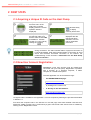
2 FIRST STEPS 2.1 Acquiring a Unique ID Code on the Heat Pump 1
3
The procedure starts in
the basic menu of the
heat pump controller
display (where the current
operation status is
displayed).
2
To acquire a new unique
ID code first make sure
that the value of both LNK
and CLD is 1. Activate
request for a new code by
clicking the
key.
4
Press directional key
to display
currently active code.
New unique ID code is
displayed after the
request has been
activated. Use it for
further registration
procedure.
If the value of either LNK or CLD is 0, it means that an error occurred
during connection. The LNK indicates status of physical connection to
Local Area Network, while CLD indicates status of connection to cloud
server and therefore successful connection to the internet. For
troubleshooting confer document »Instructions for the Heat Pump
Cloud Connection«.
2.2 New User Account Registration Before first connection to the web interface can be
established a new user account must be created and
connected with your heat pump. Registration is possible
with a browser on a personal computer, a tablet
computer or a mobile smart phone.
The web application can be accessed through:
•
the KRONOTERM web page:
http://www.kronoterm.com
by clicking on the “Cloud” icon
•
or directly on the web address:
https://cloud.kronoterm.com
14-digit ID code is needed for the registration. It can be acquired by following the procedure described
in Section 2.1.
First enter the acquired code in the UID box on the web page. Next enter desired username and
password. Validity of each entry is confirmed by a green check mark. New user account is created by
clicking on the “Registration” button.
Page|3
KRONOTERM | W e b I n t e r f a c e – U s e r m a n u a l
2.3 Login to Web Interface Use a username and a password provided during new
account registration procedure (Section 2.2) and login
into web interface by clicking the “Sign-in” button.
Forgot your username or password? If you forget your user name and/or password you
need to obtain a new unique code and repeat the
procedure for a new user account registration.
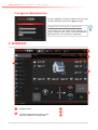
3 INTERFACE 1
2
5
3
4
1
Navigation menu
2
Head – Contains information about the
connection of the heat pump to the cloud,
currently set date time and status bar
3
4
5
Temperature overview
Settings
Submenus
Page|4
KRONOTERM | W e b I n t e r f a c e – U s e r m a n u a l
3.1 Status Bar Status bar contains all relevant information about the operation of the heat pump.
SYSTEM STATUS
1
Heat pump on
USER STATUS
1
Heat pump operating in winter mode
(heating)
Heat pump off
2
Underfloor, wall or radiator heating active
2
Tap water heating active
Active cooling active
Additional source enabled
Back-up source enabled
3
Pool heating active
Anti-legionella program active
Heat pump operating in summer mode
(cooling)
General ECO mode active
Screed drying programe active
4
Service of the heat pump required
Heat pump in starting-up state
Heat pump remotely deactivated
Defrosting of the external exchanger in
progress
3
Fast heating of tap water to a comfort
temperature in progress
Global ECO mode uses less energy for the
operation of control loops (with the exception
of tap water).
Fail-safe anti-freeze mode active
4
Additional or backup source active
5
Alternative source active
6
Passive cooling active
7
Heat pump in warning state
Heat pump in error state
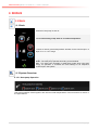
3.2 Temperature Overview The window displays data supported by your installation.
Outside temperature
Alternative source temperature
Tap water temperature
Buffer tank temperature
Temperature of the heating loop measured on
the heating line
Pool temperature
Temperature of the heating loop, measured
on the thermostat
Temperature of the heating loop, measured on
the heating line in the summer operation mode
Page|5
KRONOTERM | W e b I n t e r f a c e – U s e r m a n u a l
4 MENUS 4.1 Basic 4.1.1 Basic ON
Switch the heat pump on and off.
OFF
Activate fast heating of tap water to a comfort temperature.
Increase or reduce general temperature deviation for all control loops in 4
steps of 1°C in ± 4°C range.
AUTO
Set global heat pump operation mode.
AUTO - The heat pump operates according to the schedule.
ECO - The heat pump operates in global ECO mode which uses less
energy for operation. It overrides the local settings of all respective
control loops in the system.
4.1.2 System Overview 4.1.2.1 Heat pump Operation Heat pump operation mode together with inlet and outlet temperatures of the heat source is shown in
the upper banner.
Page|6
KRONOTERM | W e b I n t e r f a c e – U s e r m a n u a l
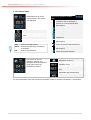
4.1.2.2 Control loops Operation, status and
temperature for all control
loops present in the system
are displayed.
Control loop operation modes:
(1,2,3)
1
Control loop in OFF mode: in
accordance with its schedule or
because of a manual deactivation
(blank space)
Control loop in COMFORT mode
Control loop icon
Control loop in ECO mode
Current temperature of the control
loop
Control loop in NORMAL mode
Control loop follows the buffer tank
temperature
Calculated target temperature
Operation status (OFF, AUTO, ON)
OFF
- Control loop deactivated.
AUTO - Control loop operating according to
its schedule.
ON
- Control loop activated.
The window shows the
operation, statuses and
temperatures of the regulation
circle, within which the
thermostat is present.
2
Control loop thermostat activated
(blank space)
Control loop thermostat deactivated
3
Control loop pump deactivated
(blank space)
Control loop pump activated
Regulation circle icon
Temperature of lifting conduit of
regulation circle.
Current temperature of the control
loop
Calculated target temperature
Operation status (OFF, AUTO, ON)
For more information about the control loop automatic modes of operation see Section 4.2 Schedules.
Page|7
KRONOTERM | W e b I n t e r f a c e – U s e r m a n u a l
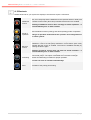
4.1.3 Shortcuts Available shortcuts for your system are displayed. All shortcuts require confirmation.
Additional
source
Manual start-up of the additional source used to speed up the heating.
Both, the heat pump and the additional source (electric heater or boiler) are
activated. Active button (blue color) indicates that the source is enabled.
Enabling of additional source does not imply its actual operation – it
will automatically turn on when needed.
Switch between summer (cooling) and winter (heating) mode of operation.
Mode of
operation
Back-up
source
Change of operation mode affects the operation and configuration of
the entire system!
Manual start-up of the back-up source. The back-up source is used as a
substitute in case of a heat pump malfunction. Active button (blue color)
indicates that the source is enabled. The source is disabled manually by
pressing the button again.
Enabling of back-up source does not imply its actual operation – it
will automatically turn on when needed.
Defrosting
Manual defrosting of the heat exchanger is an option available only for airsource heat pumps. The option is activated when the heat exchanger
freezes and defrosting is needed for proper operation.
Function can also be activated automatically!
Pool
Activation of the priority pool heating.
Page|8
KRONOTERM | W e b I n t e r f a c e – U s e r m a n u a l
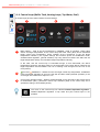
4.1.4 Control loops (Buffer Tank, Heating Loops, Tap Water, Pool) All control loops have the same interface for their settings.
1
1
2
3
Basic setting – used to set the temperature in NORMAL mode of operation. Upper value
shows set target temperature of the control loop and lower value (blue) shows calculated
target control loop temperature, which includes all the corrections of the set target
temperature induced by the system settings and functions (ECO and COMFORT mode,
weather-based regulation, general deviation). By using these two buttons we affect the set
target temperature directly and calculated target temperature indirectly.
In the case, that the control loop is controlled through a room thermostat, the above
temperature shows the set target value on the thermostat. The butons directly influence the
target temperature and thermostat. The icon of heating circle changes into the icon of the
room (house).
2
ECO and
COMFORT – Offsets from the set target control loop temperature. COMFORT
mode (increased operation) is set on the left side and ECO mode (reduced operation) is set
on the right side. Offset set in steps of 0.1°C.
3
Control loop operation status – Buttons OFF/AUTO/ON on the right side of the window serve
for deactivation (OFF), permanent control loop activation (ON) or the control loop set to
operate according to its schedule (AUTO).
The curve on the control loop icon indicates weather-dependant regulation.
Weather-dependant regulation of tap water and pool control loops is not
possible.
Page|9
KRONOTERM | W e b I n t e r f a c e – U s e r m a n u a l
4.1.4.1 Dependent control loops If the control loop is dependent it is not possible to set a target temperature and ECO and COMFORT
offsets. Dependent control loop can only be set in two modes: ON and OFF. Dependant control loop
follows the settings of another loop in the system. Picure above shows the control loop operating
according to the settings of the buffer tank.
4.1.5 Alarms Report/cancellation list of heat pump errors and warnings is displayed in Alarms window.
Alarm types:
Warning – Warning detected during operation. The system could continue to operate.
Error – Critical error occurred during operation. The system had to shutdown.
Cleared warning or error.
When critical error occurs the user is given an option to clear the errors by pressing the “Confirm”
button. The operating conditions are verified again and system will start to operate again if the error is
eliminated. If the error conditions are not resolved a service of the heat pump is required.
4.2 Schedules Schedules enable time-dependent regulation of individual control loops. Three different modes of
operation are possible:
OFF
OFF mode
Control loop deactivated.
NORMAL mode
Temperature set to the set target value (see 4.1.4 Control loops).
ECO mode
Temperature lowered from the set target temperature for the value of
ECO offset (see 4.1.4 Control loops)
COMFORT mode
The temperature is increased from the set target temperature for the
value of COMFORT offset (see 4.1.4 Control loops)
Note: In case of a weather-dependant regulation the set target temperature of the NORMAL mode
is calculated from the predefined temperature curve.
P a g e | 10
KRONOTERM | W e b I n t e r f a c e – U s e r m a n u a l
4.2.1 Schedules Overview Overview of all control loops’ schedules in the system is given in this window.
1
2
3
1
Used colour legend.
2
Graphic display of schedules sorted by individual control loops.
3
Currently chosen day of the week.
P a g e | 11
KRONOTERM | W e b I n t e r f a c e – U s e r m a n u a l
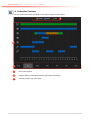
4.2.2 Control loops (Buffer Tank, Heating Loops, Tap Water, Pool, Tap Water Circulation) Schedule for individual control loop for each day of the week can be set in this window. By default all
control loops are deactivated (set to OFF).
4
5
3
2
1
1
Select the schedule’s day from the lower banner.
2
A red line is shown on the graph. It is in the OFF mode and extends over the entire time scale,
indicating that on the chosen day the heat pump will be in constant stand-by mode. Change
the heat pump schedule by pressing the grey dots at the level of the desired mode OFF,
NORMAL, ECO or NORMAL. The red line level shifts to the set mode. The dot circled with red
circle indicates an active cursor.
3
Smaller corrections for the active time point (indicated by active pointer) to a schedule can be
set by pressing »+15min« and »-15min« buttons.
Note: Maximum 6 transitions per day are enabled for a schedule.
4
The interface offers a copy/paste feature for easier editing:
1) Schedule is copied to the clipboard by pressing the »Copy« button.
2) We move to the day where we want the schedule to be copied to and press the »Paste«
button.
5
The »Clear« key is used to reset the active day’s schedule to a default OFF mode.
P a g e | 12
KRONOTERM | W e b I n t e r f a c e – U s e r m a n u a l
Note: In the case of tap water control loop or direct control loops only NORMAL or OFF modes are
available.
Note: Schedule is automatically saved 15 seconds after the last change has been made or after the
menu has been left.
4.3 System The system menu is used to:
Access the heat pump connection instructions and the web interface user manual.
Change the user account password.
Edit the names of individual control loops and set the heat pump location (name). Note:
Useful for easier heat pump identification for users with several heat pumps installed.
Set up automated e-mail notifications.
Overview and summary of heat pump operation time.
Setting of time and date on the heat pump.
Access the system information and versions.
Change the web user interface language.
Export all system parameters and temperature readings to a text document.
P a g e | 13
KRONOTERM | W e b I n t e r f a c e – U s e r m a n u a l
4.4 Trends The trends are an indispensable part of the Cloud.KRONOTERM interface. They enable a precise
overview and comparison of operation of all heating system components. The data is shown in high
capacity, well organised diagrams. We can use individual diagrams to optimise system operation and
thus reduce heating expenses. The histogram of theoretical use enables the change of electricity use
of the system. Daily, weekly and monthly use can be reviewed directly in the EURO currency.
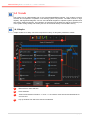
4.4.1 Graphs Graphs enable us to easily check and compare the history of all system parameter’s values.
1
2
4
3
1
Measurement value selection.
2
Event selection.
3
Time interval selection. Buttons “<<” and “>>” are used to move forward and backwards for
one time unit.
4
Pop-up window from which the events are selected.
P a g e | 14
KRONOTERM | W e b I n t e r f a c e – U s e r m a n u a l
4.4.4.1 Temperature Selection 1) Click on the icon.
2) Select temperature.
3) Temperature icon and a line are added to the diagram; the line is outlined and has a new colour
which serves as a legend.
4.4.4.2 Event Selection 1) Click on the icon.
2) Select event.
3) Event icon and a bar are added to the diagram; a bar is outlined and blue colour represents the
operation.
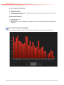
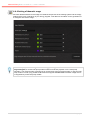
4.4.2 Sanitary water histogram The histogram enables a review of sanitary water heating history by days, weeks and months.
P a g e | 15
KRONOTERM | W e b I n t e r f a c e – U s e r m a n u a l
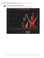
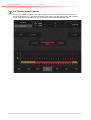
4.4.3 Histogram of heating and cooling Histogram enables an overview of heating, cooling and passive cooling through time.
P a g e | 16
KRONOTERM | W e b I n t e r f a c e – U s e r m a n u a l
4.4.4 Setting of theoretic usage We enter theoretical data on the usage of individual components of the heating system into the empty
fields and the price of electricity of your energy supplier. This data is a foundation for the generation of
a histogram of theoretic usage.
In order to display menus Setting of theoretic usage, Setting of tariff counter and Theoretical
usage histogram, a correct heat pump model number must be set ("System / Info / Heat pump
controller"). The model number is typicaly set by a technician at the heat pump setup. In case the heat
pump model in not set (n/a), please contact technical support KRONOTERM. Theoretic usage menus
are supported by most heat pump models.
P a g e | 17
KRONOTERM | W e b I n t e r f a c e – U s e r m a n u a l
4.4.5 Setting of tariff counter In the menu, select the type of tariff counter (singler tariff, double tariff) and enter the price you
purchase electricity for. In the case of a double tariff system, set daily tariff times in the schedule
below. This data is a foundation for the generation of a theoretical usage histogram.
P a g e | 18
KRONOTERM | W e b I n t e r f a c e – U s e r m a n u a l
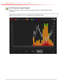
4.4.6 Theoretical usage histogram Histogram enables an overview of the history of electricity usage of individual heating system
components.
For a proper display of usage, data on component usage and price of electricty of your energy
supplier must be entered in the menu THEORETICAL USAGE SETTINGS.
P a g e | 19