1
KM 63/PGN-plus
Special Grippers · Grippers with Spindle Interface
Finger load
Mx
My
Mz
Fz
KM 63
PGN-plus 80
60.0 Nm
95.0 Nm
55.0 Nm
1500.0 N
max.
max.
max.
max.
.il c
o
r
ai
L Moments and forces apply per base jaw and may occur
simultaneously. My may arise in addition to the moment
generated by the gripping force itself.
.
w
Technical data
Description
Stroke per jaw
Gripping force
Gripping principle
Max. permitted finger length
Max. permitted weight per finger
Weight
Max. permitted speed
IP rating
Min. required supply pressure
Max. permitted supply pressure
Min. ambient temperature
Max. ambient temperature
Repeat accuracy
m
o
KM 63
PGN-plus 100
80.0 Nm
100.0 Nm
70.0 Nm
2000.0 N
ID
[mm]
[N]
[mm]
[kg]
[kg]
[min-1]
KM 63
PGN-plus 80 AS
0308471
8.0
230.0 - 310.0
I.D. gripping
100.0
0.6
1.5
20
40
6.0
60.0
-10.0
90.0
0.01
m
te
s
y
S
il
[bar]
[bar]
[°C]
[°C]
[mm]
O
ir
,s
.
c
In
KM 63
PGN-plus 80 IS
0308491
8.0
180.0 - 260.0
O.D. gripping
100.0
0.6
1.5
20
40
6.0
60.0
-10.0
90.0
0.01
w
w
KM 63
PGN-plus 100 AS
0308472
10.0
345.0 - 485.0
I.D. gripping
125.0
1.1
1.9
20
40
6.0
60.0
-10.0
90.0
0.01
KM 63
PGN-plus 100 IS
0308492
10.0
280.0 - 420.0
O.D. gripping
125.0
1.1
1.9
20
40
6.0
60.0
-10.0
90.0
0.01
L When commissioned on a machine tool, the grippers must be set to the pressure of the drive medium. Please use our setting kit, ID 0308599, for this purpose.
Grippers with the “IS” designation are for O.D. gripping, those with the “AS” designation for I.D. gripping. In the IS version, the gripper is closed via the pressure of the medium;
in the AS version, the pressure of the medium opens the gripper. Alternatively, gripping can be achieved by spring force, and the release with the pressure of the medium.
A
932
www.schunk.com
KM 63/PGN-plus
Special Grippers · Grippers with Spindle Interface
KM 63 PGN-plus 100 AS/IS
KM 63 PGN-plus 80 AS/IS
m
o
.il c
Gripper connection
Finger connection
Gripper connection
Finger connection
L Please refer to the gripper in question for more detailed information.
Suitable gripper accessories can be found in the additional views at the end of the
gripper size in question.
L Please refer to the gripper in question for more detailed information.
Suitable gripper accessories can be found in the additional views at the end of the
gripper size in question.
,s
o
r
ai
.
w
.
c
In
w
w
m
te
s
y
S
il
O
ir
A
www.schunk.com
933
KM 63/PZN-plus
Special Grippers · Grippers with Spindle Interface
Finger load
Mx
My
Mz
Fz
KM 63
PZN-plus 64
40.0 Nm
60.0 Nm
40.0 Nm
1100.0 N
max.
max.
max.
max.
.il c
o
r
ai
L Moments and forces apply per base jaw and may occur
simultaneously. My may arise in addition to the moment
generated by the gripping force itself.
.
w
Technical data
Description
Stroke per jaw
Gripping force
Gripping principle
Max. permitted finger length
Max. permitted weight per finger
Weight
Max. permitted speed
IP rating
Min. required supply pressure
Max. permitted supply pressure
Min. ambient temperature
Max. ambient temperature
Repeat accuracy
m
o
KM 63
PZN-plus 100
80.0 Nm
100.0 Nm
70.0 Nm
2000.0 N
ID
[mm]
[N]
[mm]
[kg]
[kg]
[min-1]
O
ir
,s
m
te
s
y
S
il
[bar]
[bar]
[°C]
[°C]
[mm]
.
c
In
KM 63
PZN-plus 64 IS
0308495
6.0
305.0-360.0
O.D. gripping
80.0
0.35
1.4
20
40
6.0
60.0
-10.0
90.0
0.01
w
w
KM 63
PZN-plus 100 IS
0308497
10.0
710.0-1020.0
O.D. gripping
125.0
1.1
3.0
20
40
6.0
60.0
-10.0
90.0
0.01
L When commissioned on a machine tool, the grippers must be set to the pressure of the drive medium. Please use our setting kit, ID 0308599, for this purpose.
Grippers with the “IS” designation are for O.D. gripping, those with the “AS” designation for I.D. gripping. In the IS version, the gripper is closed via the pressure of the medium;
in the AS version, the pressure of the medium opens the gripper. Alternatively, gripping can be achieved by spring force, and the release with the pressure of the medium.
A
934
www.schunk.com
KM 63/PZN-plus
Special Grippers · Grippers with Spindle Interface
KM 63 PZN-plus 100 AS/IS
KM 63 PZN-plus 64 AS/IS
m
o
.il c
Gripper connection
Finger connection
Gripper connection
Finger connection
L Please refer to the gripper in question for more detailed information.
Suitable gripper accessories can be found in the additional views at the end of the
gripper size in question.
L Please refer to the gripper in question for more detailed information.
Suitable gripper accessories can be found in the additional views at the end of the
gripper size in question.
,s
o
r
ai
.
w
.
c
In
w
w
m
te
s
y
S
il
O
ir
A
www.schunk.com
935
MC-GP/GE
Special Grippers · Miniature Grippers
Weight
22 g .. 66 g
Gripping force
0.15 N
Stroke per finger
2.2 mm
Workpiece weight
3g
m
o
.il c
Application example
o
r
ai
,s
.
c
In
.
w
w
w
m
te
l
i
O
s
Sy
r
iA
Pick & place unit for assembling circuit
boards with capacitors
MC-GE 005
Miniature Centric Gripper
Servo-electric Short-stroke Module
with MLD 50K direct drive
936
www.schunk.com
Servo-electric Linear Axis with MLD
100 direct drive
MC-GP/GE
Special Grippers · Miniature Grippers
Miniature Gripper
Single-acting miniature gripper with electric or pneumatic drive and
spring return
Area of application
Grips the smallest workpieces in clean to low-soiling environments,
such as in assembly lines and laboratories
m
o
.il c
Your advantages and benefits
o
r
ai
Simple, fast drive kinematics
for short cycle times and high cycle frequencies
.
w
Integrated stroke adjustment
for optimum adaptation to different workpieces
Flexible fingers
for gripping sensitive or asymmetrical components
Small, compact design
for minimal interfering contours and low weight
,s
.
c
In
w
w
m
te
s
y
S
il
O
ir
A
General information on the series
Working principle
Single-acting, spring return via fingers
Housing material
Aluminum
Actuation
Electric, 24 VDC, or pneumatic
Warranty
24 months
Scope of delivery
Gripper with mounted finger guard, assembly and operating manual
with manufacturer’s declaration
Maintenance
Maintenance-free
Accessories
The MC-GE or MC-GP is also available on request as a 2-finger parallel gripper.
www.schunk.com
937
MC-GP 005
Special Grippers · Miniature Grippers
m
o
.il c
.
w
Technical data
Description
Max. stroke per finger
Gripping force
Weight
Recommended workpiece weight (max.)
Minimum pressure
Maximum pressure
Closing time at max. stroke
Opening time at max. stroke
Smallest gripping Ø
Largest gripping Ø
Min. ambient temperature
Max. ambient temperature
Repeat accuracy
ID
[mm]
[N]
[kg]
[kg]
[bar]
[bar]
[s]
[s]
[mm]
[mm]
[°C]
[°C]
[mm]
,s
s
y
S
il
m
te
.
c
In
MC-GP 005
0305600
2.2
0.15
0.022
0.003
2.0
7.0
0.05
0.04
0.6
5.0
5.0
55.0
0.1
O
ir
A
938
o
r
ai
www.schunk.com
w
w
MC-GP 005
Special Grippers · Miniature Grippers
Main views
m
o
.il c
o
r
ai
.
w
,s
m
te
The drawing shows the gripper in the basic position with open fingers.
FME finger module
s
y
S
il
.
c
In
A,a
w
w
Main/direct connection, gripper opening
Gripper connection
Width across flats
Preset gripper diameter
O
ir
A
If a finger is damaged, it suffices to simply replace the FME finger module.
Description
ID
FME
0305603
www.schunk.com
939
MC-GE 005
Special Grippers · Miniature Grippers
m
o
.il c
.
w
Technical data
Description
Max. stroke per finger
Gripping force
Weight
Recommended workpiece weight (max.)
Opening time at max. stroke
Closing time at max. stroke
Smallest gripping Ø
Largest gripping Ø
Min. ambient temperature
Max. ambient temperature
Repeat accuracy
Voltage supply
Nominal power
Maximum power
ID
[mm]
[N]
[kg]
[kg]
[s]
[s]
[mm]
[mm]
[°C]
[°C]
[mm]
[V]
[A]
[A]
,s
m
te
s
y
S
il
O
ir
.
c
In
MC-GE 005
0305601
2.2
0.15
0.066
0.003
0.04
0.04
0.6
5.0
5.0
55.0
0.2
24.0
0.2
1.0
A
940
o
r
ai
www.schunk.com
w
w
MC-GE 005
Special Grippers · Miniature Grippers
Main views
m
o
.il c
o
r
ai
.
w
,s
m
te
The drawing shows the gripper in the basic position with open fingers.
FME finger module
s
y
S
il
.
c
In
w
w
Gripper connection
Width across flats
Preset gripper diameter
2-wire cable, length 200 mm, cross section 2 x 0.08 mm2
PMW module
O
ir
A
If a finger is damaged, it suffices to simply replace the FME finger module.
Description
ID
FME
0305603
Protective diode (provided by customer)
The PMW (pulse-width modulation) module is employed for the purpose of heat reduction
with an ON time of > 5 min.
Description
ID
PWM-Modul
0305602
www.schunk.com
941
MGM
Special Grippers · Manually Guided Grippers
Weight
65 g
Workpiece weight
3g
Max. finger opening
3 mm .. 4 mm
m
o
.il c
Application example
o
r
ai
,s
.
c
In
.
w
w
w
m
te
l
i
O
s
Sy
r
iA
For mounting gears in the watch
and clock-making industry
Finger attachment
(parallel or centric gripper
available)
Front part of housing
with drive unit
942
www.schunk.com
Button for initiating
the gripping cycle
Rear part of housing
with battery compartment
MGM
Special Grippers · Manually Guided Grippers
Manually Guided Gripper
MGM manual miniature gripper with 2-finger parallel or 3-finger
centric gripper attachment
Area of application
For use as a gripping tool for small to very small components in
assembly, sorting tasks, laboratory work, precise and manual
joining processes and in many other applications with miniature
components
m
o
.il c
Your advantages and benefits
o
r
ai
Ergonomic shape
for comfortable, fatigue-free working
.
w
Replaceable fingers
for handling all kinds of components
Operation
Operation using a pushbutton
Time-controlled gripping cycle
,s
.
c
In
w
w
m
te
s
y
S
il
O
ir
A
General information on the series
Length
Approx. 160 mm without gripper fingers
Drive
Slow cycle: 1 x type AAA micro-battery and 1 x aluminum packing block
Fast cycle: 2 x type AAA micro-batteries
Scope of delivery
Gripper drive and finger attachment
Batteries not included in scope of delivery
Warranty
24 months
Period of use
Approx. 1 hour continuous operation with 1 set of batteries
www.schunk.com
943
MGM
Special Grippers · Manually Guided Grippers
m
o
.il c
o
r
ai
.
w
Technical data
Description
ID
No. of fingers
Jaw design
Weight without batteries
[kg]
Time for “Open-Closed-Open” cycle (fast) [s]
Time for “Open-Closed-Open” cycle (slow)[s]
Max. workpiece weight
[kg]
Max. finger opening
[mm]
MGM
0301001
2
parallel-narrow
0.065
1.0
2.0
0.003
4.0
,s
m
te
.
c
In
MGM
0301002
2
parallel-wide
0.065
1.0
2.0
0.003
4.0
w
w
MGM
0301003
3
centric-narrow
0.065
1.0
2.0
0.003
4.0
MGM
0301004
3
centric-wide
0.065
1.0
2.0
0.003
4.0
L The maximum workpiece weight that can be gripped depends upon the characteristics of the workpiece (shape, surface, material, ...) and varies within a certain tolerance range.
s
y
S
il
O
ir
A
944
www.schunk.com
MGM
Special Grippers · Manually Guided Grippers
Main views
m
o
.il c
o
r
ai
.
w
,s
.
c
In
w
w
m
te
The drawing shows the gripper in the basic position with open fingers, and does not
include the options described below.
s
y
S
il
MGM 2-finger parallel finger attachment
MGM 3-finger centric finger attachment
O
ir
A
Finger attachment MGM, 2-finger, parallel–wide Finger attachment MGM, 2-finger, parallel–narrow
Finger attachment MGM, 3-finger, centric–wide Finger attachment MGM, 3-finger, centric–narrow
The MGM finger attachments are available with narrow and wide fingers for the different
versions.
Description
No. of fingers
Finger design
Weight
ID
[kg]
Finger attachments MGM 0301010
2
parallel–narrow
0.005
Finger attachments MGM 0301011
2
parallel–wide
0.005
The MGM finger attachments are available with narrow and wide fingers for the different
versions.
Description
No. of fingers
Finger design
Weight
ID
[kg]
Finger attachments MGM 0301012
3
centric–narrow
0.005
Finger attachments MGM 0301013
3
centric–wide
0.005
www.schunk.com
945
SGH
Special Grippers · Gripping Hand
Weight
1.18 kg
Gripping force per finger
5N
Workpiece weight
form-fit clamping
6 kg
m
o
.il c
Application example
o
r
ai
,s
.
c
In
.
w
w
w
m
te
l
i
O
s
Sy
r
iA
7-DOF light-weight arm and gripping hand
for applications in research and
development and in service robotics
946
SGH Servo-electric Gripping Hand
PW 70 Rotary Tilt Unit
www.schunk.com
LWA 2 Light-weight Arm
SGH
Special Grippers · Gripping Hand
Gripping Hand
Servo-electric gripping hand with eight programmable axes and
joints
Area of application
For universal use, and ideally suited for all handling tasks requiring
the precise, force-controlled gripping of difficult-to-grip workpieces or
materials (e.g. foam, glass, highly-elastic rubber, ...).
m
o
.il c
Your advantages and benefits
Three multi-jointed fingers
(two of which can be rotated)
for the form-fit or friction-locked gripping of various workpieces
without retooling
o
r
ai
.
w
Four integrated motors
for the precise closed-loop control of gripping force, speed and
position
Common communication interface RS-232
for transmitting all gripper parameters, such as speed, stroke,
position and motor current
Compact design
despite the integration of four motors and gear mechanisms
,s
.
c
In
w
w
m
te
s
y
S
il
O
ir
A
General information on the series
Options and special information
Scope of delivery
- Separate communication and control box
- Four DC servo-motors, three of which with patented decoupling gear
- Incremental sensors for all motors, control and test software
- Stands for safe table mounting, maintenance kit
Strain gauges
in fingers for measuring occurring forces and moments
24 V DC version
for mobile use
Communication
Trigger box reached via RS-232 interface
Warranty
12 months
www.schunk.com
947
SGH
Special Grippers · Gripping Hand
Drive design
m
o
.il c
o
r
ai
.
w
,s
m
te
Innovative drive design
A finger with two independent joints is driven by just one motor, saving both weight and
volume. The SGH is therefore slim like the human hand. The result is that the fingers have
good accessibility to workpieces and a large range of movement. This drive design is
achieved using a special gear mechanism, which either drives both finger joints
simultaneously, causing the first finger joint to move relative to the hand surface, or drives
just the front joint, causing the second finger joint to move relative to the first finger joint.
s
y
S
il
.
c
In
w
w
The finger is completely opened.
The first finger joint rests, the second joint continues to move.
The finger is completely closed.
The first finger joint has opened, the second joint begins to open.
O
ir
A
The gear mechanism between the hand surface and the first finger joint consists of two
worm gears and the force-type connection for finger joint 1.
948
The first finger joint is driven directly, the second joint by means of a Bowden cable, which
is secured to a gear situated on the axis of the first finger joint.
www.schunk.com
SGH
Special Grippers · Gripping Hand
Processes in the gear mechanism when a finger closes
m
o
.il c
o
r
ai
.
w
,s
m
te
When neither the first nor second finger joint is touching the workpiece, both axes
are driven, whereby the input torque for finger joint 1 is conveyed by means of a
force-type connection (the two red diaphragm springs that hold the narrow gear
wheel). There is no relative movement between finger joint 2 and finger joint 1,
s
y
S
il
.
c
In
w
w
Finger joint 2
Finger joint 1
Input shaft
the two finger joints rotate together around finger axis 1. When finger joint 1 is
touching the workpiece, joint 1 can no longer move and the two diaphragm springs
can no longer hold the narrow gear. The latter disengages, breaking the friction lock.
Now only joint 2 continues moving, while joint 1 is stationary.
Range of movement
-r O
iA
180°
180°
45°
0°
140°
0°
0°
0°
The SCHUNK SGH gripping hand has three fingers each with two joints. In addition, the two outer fingers can be rotated by 180° around the hand surface.
www.schunk.com
949
SGH
Special Grippers · Gripping Hand
m
o
.il c
o
r
ai
.
w
Technical data
c.
Description
ID
Force per finger
[N]
Swivel ranges of finger joint 1
[°]
Swivel ranges of finger joint 2
[°]
Swivel ranges, splaying movement
[°]
Weight of hand
[kg]
Max. workpiece weight (recommended for form-fit clamping) [kg]
Time for complete finger stroke (both joints)
[s]
Time for splaying movement (180°)
[s]
Repeat accuracy
[°]
Power supply
[V AC]
Communication with trigger box
Axes
Fingers
Fingers with rotating movement
Joints per finger
Motors per finger
Motors per hand
I, n
s
m
ts e
y
S
il
O
ir
A
w
w
SGH
0306400
5.0
140.0
45.0
180.0
1.18
6.0
1.0
0.4
0.1
220.0
RS-232
8
3
2
2
1
4
L The stated information on the force, repeat accuracy, workpiece weight and finger stroke assumes compliance with defined motion and environmental parameters.
950
www.schunk.com
SGH
Special Grippers · Gripping Hand
Main views
m
o
.il c
o
r
ai
.
w
,s
m
te
The drawing shows the gripper in the basic position with open fingers.
Trigger box
s
y
S
il
.
c
In
w
w
Cable outlet
Joint 1 swivel range
Joint 2 swivel range
Splaying joint swivel range
O
ir
A
Actuating connector
Mains connector
www.schunk.com
951
Accessories
m
o
.il c
.
w
o
r
ai
,s
m
te
s
y
S
il
A
O
ir
.
c
In
w
w
ACCESSORIES
Accessories
Series
Size
Page
Accessories
Series
Size
Page
Accessories
Inductive Proximity Switches IN
954
Fastening Elements
IN
5
956
Guide Sleeves
1072
IN
8
958
PAM
1074
IN
40
960
Valves and Screw Connections
1076
IN
60
962
SDV-P
1078
IN
65
964
WV
IN
80
966
SWV
IN
B-80/80SL
968
DSV
IN
120
972
RMS
22
RMS
80
22
MMS
22-SA
MMS
976
.
w
w
w
30
1082
1084
o
r
ai
974
Magnetic Switches MMS
MMS
.il c
970
Reed Switches RMS
m
o
1080
978
980
982
984
Switch Accessories
c.
SST
NHG
I, n
s
m
ts e
y
S
il
iA
-r O
986
990
Connectors/Feeder Cables
994
Sensor Testers
998
Sensor Distributor
1000
V2
1002
V4
1006
V8
1010
Measuring Systems
APS-M1
1014
FPS/FPS-A/FPS Software
1018
FMS/FMS-A/FMS-ZBA/-ZBP
1026
Finger Blanks and Intermediate Jaws
1036
ABR for MPG
1038
ABR for MPZ
1042
ABR-plus/SBR-plus
1044
ABR for PGN/PZN
1048
RB for KTG
1052
RB for KGG
1054
RB for DKG-RR
1058
ASB/SBR for UFG
1060
ZBH for PFH
1062
Clamping Inserts for Gripper Fingers
Quentes
1066
HM
1068
HKI
1070
www.schunk.com
953
IN
Accessories · Sensor System · Inductive Proximity Switches
Inductive Proximity Switches
Inductive proximity switches are used to monitor the current position of automation components. They are available from SCHUNK in the versions IN (sensor with 30 cm molded cable and
cable connector) or INK (sensor with 2 m long feeder cable and litz wires for wiring).
m
o
.il c
o
r
ai
.
w
,s
.
c
In
w
w
m
te
Function description
O
ir
s
y
S
il
Your advantages and benefits
With their oscillator coil, inductive proximity switches produce a high-frequency,
alternating magnetic field. This field occurs on the active surface of the sensor.
If a metal object enters the field, it draws energy from the magnetic field, thereby
reducing the oscillation amplitude. This change is detected, and the sensor switches.
A
Mounting through bracket
for simple, fast assembly
Version with LED display
for checking the switching state directly at the sensor
Version with connector
for easy, rapid replacement of the extension cable
Ultra-flexible PUR cable
for a long life and resistance to many chemicals
Proximity switch can be installed flush
for minimal interfering contours in the application
954
www.schunk.com
IN
Accessories · Sensor System · Inductive Proximity Switches
Application example
Area of application
For monitoring of gripping and rotary modules, linear
modules and robot accessories. Inductive SCHUNK
sensors detect metals without contact and are resistant
to vibration, dust and humidity.
m
o
.il c
o
r
ai
.
w
,s
Plug-in IN Sensors
m
te
s
y
S
il
PSK Swivel Head
O
ir
A
.
c
In
w
w
PGN 2-Finger Parallel Gripper
with ABR finger blanks
PZN 3-Finger Centric Gripper
with workpiece-specific
gripper fingers
General information
Notes
Protection class according to DIN 40050
IP 67 when connected
Voltage
10 – 30 V DC, residual ripple < 15 %
Switching method
PNP switching
Warranty
24 months
SCHUNK gripping, rotary and linear modules and robot accessory components must
always be ordered from SCHUNK with the matching sensors, as these are ideally
adapted to work together.
If major characteristics such as switching distance, switching function, hysteresis and
voltage are largely the same, then proximity switches from other manufacturers may
be used instead of inductive proximity switches (IN, INK) from SCHUNK.
However, if proximity switches from other manufacturers are used, SCHUNK cannot
guarantee either their function or their functional reliability.
www.schunk.com
955
IN 5
Accessories · Sensor System · Inductive Proximity Switches
Circuit diagram of closer
1
4
3
m
o
.il c
.
w
Technical data
Description
ID
Switching function
Switching distance
Hysteresis of nominal switching distance
Switching method
Cable length
Cable connector/cable end
Type of voltage
Nominal voltage
Min. voltage
Max. voltage
Voltage drop
Max. power on contact
Min. ambient temperature
Max. ambient temperature
Max. switching frequency
IP rating (sensor)
IP rating (connector, plugged in)
LED display on sensor
Cable diameter
Min. bending radius (dynamic)
Min. bending radius (static)
No. of wires
Wire cross section
[mm]
956
[V]
[V]
[V]
[V]
[A]
[°C]
[°C]
[Hz]
s
y
S
il
m
te
[mm]
[mm]
[mm]
[mm2]
.
c
In
IN 5/S-M8
0301469
Closer
1.0
< 15%
PNP
30.0
M8
DC
24.0
10.0
30.0
1.5
0.2
-25.0
70.0
1000.0
67
67
No
3.5
35.0
17.5
3
0.14
,s
[cm]
O
ir
A
o
r
ai
www.schunk.com
w
w
IN 5/S-M12
0301569
Closer
1.0
< 15%
PNP
30.0
M12
DC
24.0
10.0
30.0
1.5
0.2
-25.0
70.0
1000.0
67
67
No
3.5
35.0
17.5
3
0.14
INK 5/S
0301501
Closer
1.0
< 15%
PNP
200.0
Open wire
DC
24.0
10.0
30.0
1.5
0.2
-25.0
70.0
1000.0
67
67
No
3.5
35.0
17.5
3
0.14
IN 5
Accessories · Sensor System · Inductive Proximity Switches
M8 connector
IN 5/S sensor
m
o
.il c
Active sensor surface
o
r
ai
.
w
,s
M12 connector
.
c
In
w
w
m
te
s
y
S
il
O
ir
A
www.schunk.com
957
IN 8
Accessories · Sensor System · Inductive Proximity Switches
Circuit diagram of closer
1
4
3
m
o
.il c
.
w
Technical data
Description
ID
Switching function
Switching distance
Hysteresis of nominal switching distance
Switching method
Cable length
Cable connector/cable end
Type of voltage
Nominal voltage
Min. voltage
Max. voltage
Voltage drop
Max. power on contact
Min. ambient temperature
Max. ambient temperature
Max. switching frequency
IP rating (sensor)
IP rating (connector, plugged in)
LED display on sensor
Cable diameter
Min. bending radius (dynamic)
Min. bending radius (static)
No. of wires
Wire cross section
[mm]
958
[V]
[V]
[V]
[V]
[A]
[°C]
[°C]
[Hz]
s
y
S
il
m
te
[mm]
[mm]
[mm]
[mm2]
.
c
In
IN 8/S-M8
0301481
Closer
0.8
< 15%
PNP
30.0
M12
DC
24.0
10.0
30.0
1.5
0.2
-25.0
70.0
1000.0
67
67
No
3.5
35.0
17.5
3
0.14
,s
[cm]
O
ir
A
o
r
ai
www.schunk.com
w
w
IN 8/S-M12
0301581
Closer
0.8
< 15%
PNP
30.0
M12
DC
24.0
10.0
30.0
1.5
0.2
-25.0
70.0
1000.0
67
67
No
3.5
35.0
17.5
3
0.14
INK 8/S
9700052
Closer
0.8
< 15%
PNP
200.0
Open wire
DC
24.0
10.0
30.0
1.5
0.2
-25.0
70.0
1000.0
67
67
No
3.5
35.0
17.5
3
0.14
IN 8
Accessories · Sensor System · Inductive Proximity Switches
M8 connector
IN 8/S sensor
m
o
.il c
Active sensor surface
o
r
ai
.
w
,s
M12 connector
.
c
In
w
w
m
te
s
y
S
il
O
ir
A
www.schunk.com
959
IN 40
Accessories · Sensor System · Inductive Proximity Switches
Circuit diagram of closer
Circuit diagram of opener
1
1
4
4
3
3
m
o
.il c
.
w
Technical data
Description
ID
Switching function
Switching distance
Hysteresis of nominal switching distance
Switching method
Cable length
Cable connector/cable end
Type of voltage
Nominal voltage
Min. voltage
Max. voltage
Voltage drop
Max. power on contact
Min. ambient temperature
Max. ambient temperature
Max. switching frequency
IP rating (sensor)
IP rating (connector, plugged in)
LED display on sensor
Cable diameter
Min. bending radius (dynamic)
Min. bending radius (static)
No. of wires
Wire cross section
[mm]
[cm]
960
[V]
[V]
[V]
[V]
[A]
[°C]
[°C]
[Hz]
IN 40/S-M8
0301474
Closer
0.8
< 15%
PNP
30.0
M8
DC
24.0
10.0
30.0
1.5
0.2
-25.0
70.0
1000.0
67
67
Yes
3.5
35.0
17.5
3
0.14
[mm]
[mm]
[mm]
[mm2]
.
c
In
IN 40/S-M12
0301574
Closer
0.8
< 15%
PNP
30.0
M12
DC
24.0
10.0
30.0
1.5
0.2
-25.0
70.0
1000.0
67
67
Yes
3.5
35.0
17.5
3
0.14
,s
m
te
s
y
S
il
O
ir
A
o
r
ai
w
w
INK 40/S
0301555
Closer
0.8
< 15%
PNP
200.0
Open wire
DC
24.0
10.0
30.0
1.5
0.2
-25.0
70.0
1000.0
67
67
Yes
3.5
35.0
17.5
3
0.14
www.schunk.com
IN 40/O-M8
0301484
Opener
0.8
< 15%
PNP
30.0
M8
DC
24.0
10.0
30.0
1.5
0.2
-25.0
70.0
1000.0
67
67
Yes
3.5
35.0
17.5
3
0.14
IN 40/O-M12
0301584
Opener
0.8
< 15%
PNP
30.0
M12
DC
24.0
10.0
30.0
1.5
0.2
-25.0
70.0
1000.0
67
67
Yes
3.5
35.0
17.5
3
0.14
INK 40/O
0301556
Opener
0.8
< 15%
PNP
200.0
Open wire
DC
24.0
10.0
30.0
1.5
0.2
-25.0
70.0
1000.0
67
67
Yes
3.5
35.0
17.5
3
0.14
IN 40
Accessories · Sensor System · Inductive Proximity Switches
M8 connector
IN 40 sensor
m
o
.il c
Active sensor surface
o
r
ai
.
w
,s
M12 connector
.
c
In
w
w
m
te
s
y
S
il
O
ir
A
www.schunk.com
961
IN 60
Accessories · Sensor System · Inductive Proximity Switches
Circuit diagram of closer
1
4
3
m
o
.il c
.
w
Technical data
Description
ID
Switching function
Switching distance
Hysteresis of nominal switching distance
Switching method
Cable length
Cable connector/cable end
Type of voltage
Nominal voltage
Min. voltage
Max. voltage
Voltage drop
Max. power on contact
Min. ambient temperature
Max. ambient temperature
Max. switching frequency
IP rating (sensor)
IP rating (connector, plugged in)
LED display on sensor
Cable diameter
Min. bending radius (dynamic)
Min. bending radius (static)
No. of wires
Wire cross section
[mm]
962
[V]
[V]
[V]
[V]
[A]
[°C]
[°C]
[Hz]
s
y
S
il
m
te
[mm]
[mm]
[mm]
[mm2]
.
c
In
IN 60/S-M8
0301485
Closer
1.5
< 15%
PNP
30.0
M8
DC
24.0
10.0
30.0
1.5
0.2
-25.0
70.0
1000.0
67
67
No
3.5
35.0
17.5
3
0.14
,s
[cm]
O
ir
A
o
r
ai
www.schunk.com
w
w
IN 60/S-M12
0301585
Closer
1.5
< 15%
PNP
30.0
M12
DC
24.0
10.0
30.0
1.5
0.2
-25.0
70.0
1000.0
67
67
No
3.5
35.0
17.5
3
0.14
INK 60/S
0301553
Closer
1.5
< 15%
PNP
200.0
Open wire
DC
24.0
10.0
30.0
1.5
0.2
-25.0
70.0
1000.0
67
67
No
3.5
35.0
17.5
3
0.14
IN 60
Accessories · Sensor System · Inductive Proximity Switches
M8 connector
IN 60/S sensor
m
o
.il c
Active sensor surface
o
r
ai
.
w
,s
M12 connector
.
c
In
w
w
m
te
s
y
S
il
O
ir
A
www.schunk.com
963
IN 65
Accessories · Sensor System · Inductive Proximity Switches
Circuit diagram of closer
1
4
3
m
o
.il c
.
w
Technical data
Description
ID
Switching function
Switching distance
Hysteresis of nominal switching distance
Switching method
Cable length
Cable connector/cable end
Type of voltage
Nominal voltage
Min. voltage
Max. voltage
Voltage drop
Max. power on contact
Min. ambient temperature
Max. ambient temperature
Max. switching frequency
IP rating (sensor)
IP rating (connector, plugged in)
LED display on sensor
Cable diameter
Min. bending radius (dynamic)
Min. bending radius (static)
No. of wires
Wire cross section
[mm]
964
[V]
[V]
[V]
[V]
[A]
[°C]
[°C]
[Hz]
s
y
S
il
m
te
[mm]
[mm]
[mm]
[mm2]
.
c
In
IN 65/S-M8
0301476
Closer
1.5
< 15%
PNP
30.0
M8
DC
24.0
10.0
30.0
1.5
0.2
-25.0
70.0
1000.0
67
67
Yes
3.5
35.0
17.5
3
0.14
,s
[cm]
O
ir
A
o
r
ai
www.schunk.com
w
w
IN 65/S-M12
0301576
Closer
1.5
< 15%
PNP
30.0
M12
DC
24.0
10.0
30.0
1.5
0.2
-25.0
70.0
1000.0
67
67
Yes
3.5
35.0
17.5
3
0.14
INK 65/S
0301554
Closer
1.5
< 15%
PNP
200.0
Open wire
DC
24.0
10.0
30.0
1.5
0.2
-25.0
70.0
1000.0
67
67
No
3.5
35.0
17.5
3
0.14
IN 65
Accessories · Sensor System · Inductive Proximity Switches
M8 connector
IN 65/S sensor
m
o
.il c
Active sensor surface
LED
o
r
ai
.
w
,s
M12 connector
.
c
In
w
w
m
te
s
y
S
il
O
ir
A
www.schunk.com
965
IN 80
Accessories · Sensor System · Inductive Proximity Switches
Circuit diagram of closer
Circuit diagram of opener
1
1
4
4
3
3
m
o
.il c
.
w
Technical data
Description
ID
Switching function
Switching distance
Hysteresis of nominal switching distance
Switching method
Cable length
Cable connector/cable end
Type of voltage
Nominal voltage
Min. voltage
Max. voltage
Voltage drop
Max. power on contact
Min. ambient temperature
Max. ambient temperature
Max. switching frequency
IP rating (sensor)
IP rating (connector, plugged in)
LED display on sensor
Cable diameter
Min. bending radius (dynamic)
Min. bending radius (static)
No. of wires
Wire cross section
[mm]
[cm]
966
[V]
[V]
[V]
[V]
[A]
[°C]
[°C]
[Hz]
IN 80/S-M8
0301478
Closer
1.5
< 15%
PNP
30.0
M8
DC
24.0
10.0
30.0
1.5
0.2
-25.0
70.0
1000.0
67
67
Yes
3.5
35.0
17.5
3
0.14
[mm]
[mm]
[mm]
[mm2]
.
c
In
IN 80/S-M12
0301578
Closer
1.5
< 15%
PNP
30.0
M12
DC
24.0
10.0
30.0
1.5
0.2
-25.0
70.0
1000.0
67
67
Yes
3.5
35.0
17.5
3
0.14
,s
m
te
s
y
S
il
O
ir
A
o
r
ai
w
w
INK 80/S
0301550
Closer
1.5
< 15%
PNP
200.0
Open wire
DC
24.0
10.0
30.0
1.5
0.2
-25.0
70.0
1000.0
67
67
Yes
3.5
35.0
17.5
3
0.14
www.schunk.com
IN 80/O-M8
0301488
Opener
1.5
< 15%
PNP
30.0
M8
DC
24.0
10.0
30.0
1.5
0.2
-25.0
70.0
1000.0
67
67
Yes
3.5
35.0
17.5
3
0.14
IN 80/0-M12
0301588
Opener
1.5
< 15%
PNP
30.0
M12
DC
24.0
10.0
30.0
1.5
0.2
-25.0
70.0
1000.0
67
67
Yes
3.5
35.0
17.5
3
0.14
INK 80/O
0301551
Opener
1.5
< 15%
PNP
200.0
Open wire
DC
24.0
10.0
30.0
1.5
0.2
-25.0
70.0
1000.0
67
67
Yes
3.5
35.0
17.5
3
0.14
IN 80
Accessories · Sensor System · Inductive Proximity Switches
M8 connector
IN 80 sensor
m
o
.il c
Active sensor surface
LED
o
r
ai
.
w
,s
M12 connector
.
c
In
w
w
m
te
s
y
S
il
O
ir
A
www.schunk.com
967
IN B-80/80SL
Accessories · Sensor System · Inductive Proximity Switches
Circuit diagram of closer
1
4
3
m
o
.il c
.
w
Technical data
Description
[mm]
968
m
te
s
y
S
il
O
ir
A
,s
[cm]
[V]
[V]
[V]
[V]
[A]
[°C]
[°C]
[Hz]
.
c
In
IN-B 80/S-M8
0301477
Closer
1.5
< 15%
PNP
ID
Switching function
Switching distance
Hysteresis of nominal switching distance
Switching method
Cable length
Cable connector/cable end
Type of voltage
Nominal voltage
Min. voltage
Max. voltage
Voltage drop
Max. power on contact
Min. ambient temperature
Max. ambient temperature
Max. switching frequency
IP rating (sensor)
IP rating (connector, plugged in)
LED display on sensor
Cable diameter
Min. bending radius (dynamic)
Min. bending radius (static)
No. of wires/contacts
Wire cross section
o
r
ai
M8
DC
24.0
10.0
30.0
1.5
0.2
-25.0
70.0
1000.0
67
67
Yes
[mm]
[mm]
[mm]
3
[mm2]
www.schunk.com
w
w
IN 80/SL-M12
0301529
Closer
3.0
< 15%
PNP
30.0
M12
DC
24.0
10.0
30.0
1.5
0.2
-25.0
70.0
1000.0
67
67
Yes
3.5
35.0
17.5
3
0.14
INK 80/SL
0301579
Closer
3.0
< 15%
PNP
200.0
Open wire
DC
24.0
10.0
30.0
1.5
0.2
-25.0
70.0
1000.0
67
67
Yes
3.5
35.0
17.5
3
0.14
IN B-80/80SL
Accessories · Sensor System · Inductive Proximity Switches
IN 80/SL sensor
IN B-80 sensor
m
o
Active sensor surface
LED
.il c
Active sensor surface
LED
o
r
ai
.
w
,s
.
c
In
w
w
m
te
s
y
S
il
O
ir
A
www.schunk.com
969
IN 120
Accessories · Sensor System · Inductive Proximity Switches
Circuit diagram of closer
1
4
3
m
o
.il c
.
w
Technical data
Description
ID
Switching function
Switching distance
Hysteresis of nominal switching distance
Switching method
Cable length
Cable connector/cable end
Type of voltage
Nominal voltage
Min. voltage
Max. voltage
Voltage drop
Max. power on contact
Min. ambient temperature
Max. ambient temperature
Max. switching frequency
IP rating (sensor)
IP rating (connector, plugged in)
LED display on sensor
Cable diameter
Min. bending radius (dynamic)
Min. bending radius (static)
No. of wires
Wire cross section
[mm]
[cm]
970
[V]
[V]
[V]
[V]
[A]
[°C]
[°C]
[Hz]
[mm]
[mm]
[mm]
[mm2]
.
c
In
IN 120/S-M12
0301592
Closer
2.0
< 15%
PNP
30.0
M12
DC
24.0
10.0
30.0
1.5
0.2
-25.0
70.0
1000.0
67
67
No
3.5
35.0
17.5
3
0.14
,s
m
te
s
y
S
il
O
ir
A
o
r
ai
www.schunk.com
w
w
INK 120/S
0301562
Closer
2.0
< 15%
PNP
200.0
Open wire
DC
24.0
10.0
30.0
1.5
0.2
-25.0
70.0
1000.0
67
67
No
3.5
35.0
17.5
3
0.14
IN 120
Accessories · Sensor System · Inductive Proximity Switches
M12 connector
IN 120/S sensor
m
o
.il c
Active sensor surface
o
r
ai
.
w
,s
.
c
In
w
w
m
te
s
y
S
il
O
ir
A
www.schunk.com
971
RMS
Accessories · Sensor System · Reed Switches
Reed Switches
Reed switches are mechanical switches that react to the presence of magnetic fields (magnets). They are frequently used as low-price alternatives to electronic magnetic switches (MMS).
m
o
.il c
o
r
ai
.
w
,s
.
c
In
w
w
m
te
Function description
O
ir
s
y
S
il
Your advantages and benefits
Reed switches consist of tiny, metal contacts (reeds). Under the influence of a
magnetic field, they bend and touch one another, closing the contact.
A
Economical
for cost-saving applications
Installed in the sensor slot
for space-saving, simple and fast assembly
Version with connector
for easy, rapid replacement of the extension cable
Ultra-flexible PUR cable
for a long life and resistance to many chemicals
972
www.schunk.com
RMS
Accessories · Sensor System · Reed Switches
Application example
Area of application
For monitoring of gripping and rotary modules, linear
modules and robot accessories. Reed switches from
SCHUNK detect metals without contact or wear and
are resistant to dust and humidity. Magnetic switches
are fitted in slots and therefore do not form any
additional interfering contours. Please note that not all
SCHUNK products with sensor slot can be monitored
using low-cost reed switches.
m
o
.il c
o
r
ai
.
w
,s
RMS Reed Switches for mounting in
the C-slot of the gripper
.
c
In
w
w
m
te
s
y
S
il
Sealed 3-Finger Centric Gripper
Workpiece-specific Gripper Fingers
O
ir
A
General information
Notes
Material
Sensor housing: PA in the RMS 22, stainless steel in the RMS 80
Cable: PUR sheathing
Mounting
Clamps in sensor slot (RMS 22) / brackets (RMS 80)
Protection class to DIN 40050
IP 67 when connected
Warranty
24 months
SCHUNK gripper, rotary and linear modules and robot accessory components that are
to be monitored by RMS slot-fitted reed switches can generally only be reliably
monitored with the appropriate RMS reed switches from SCHUNK. Sensors and
products are matched on the basis of the relationships between the parameters type
and field strength of the magnet, distance, wall thickness and wall material of the
magnet and the sensor, and the orientation and sensitivity of the sensor itself.
For this reason, sensors from other manufacturers employed in SCHUNK products
rarely give satisfactory switching results.
www.schunk.com
973
RMS 22
Accessories · Sensor System · Reed Switches
Circuit diagram of closer
1
4
3
m
o
.il c
.
w
Technical data
Description
ID
Switching function
Switching method
Cable length
Cable connector/cable end
Type of voltage
Max. voltage DC
Voltage drop DC
Max. current on contact DC
Type of voltage
Max. voltage AC
Voltage drop AC
Max. power on contact AC
Min. ambient temperature
Max. ambient temperature
Typical switching time
IP rating (sensor)
IP rating (connector, plugged in)
LED display on sensor
Cable diameter
Min. bending radius (dynamic)
Min. bending radius (static)
No. of wires
Wire cross section
[cm]
s
y
S
il
974
[V]
[V]
[A]
[°C]
[°C]
[s]
[mm]
[mm]
[mm]
[mm2]
,s
m
te
[V]
[V]
[A]
O
ir
A
o
r
ai
.
c
In
RMS 22-S-M8
0377720
Closer
PNP, NPN
30.0
M8
DC
120.0
0.0
0.4
AC
120.0
0.0
0.4
-5.0
70.0
0.01
67
67
No
2.1
21.0
10.5
2
0.14
www.schunk.com
w
w
RMS 22
Accessories · Sensor System · Reed Switches
M8 connector
RMS 22 sensor
m
o
.il c
Active sensor surface
o
r
ai
.
w
,s
.
c
In
w
w
m
te
s
y
S
il
O
ir
A
www.schunk.com
975
RMS 80
Accessories · Sensor System · Reed Switches
Circuit diagram of closer
1
4
3
m
o
.il c
.
w
Technical data
Description
ID
Switching function
Switching method
Cable length
Cable connector/cable end
Type of voltage
Max. voltage DC
Voltage drop DC
Max. current on contact DC
Type of voltage
Max. voltage AC
Voltage drop AC
Max. power on contact AC
Min. ambient temperature
Max. ambient temperature
Typical switching time
IP rating (sensor)
IP rating (connector, plugged in)
LED display on sensor
Cable diameter
Min. bending radius (dynamic)
Min. bending radius (static)
No. of wires
Wire cross section
[cm]
s
y
S
il
976
[V]
[V]
[A]
[°C]
[°C]
[s]
[mm]
[mm]
[mm]
[mm2]
,s
m
te
[V]
[V]
[A]
O
ir
A
o
r
ai
.
c
In
RMS 80-S-M8
0377721
Closer
PNP, NPN
30.0
M8
DC
120.0
0.0
0.4
AC
120.0
0.0
0.4
-5.0
70.0
0.01
67
67
No
2.1
21.0
10.5
2
0.14
www.schunk.com
w
w
RMS 80
Accessories · Sensor System · Reed Switches
M8 connector
RMS 80 sensor
m
o
.il c
Active sensor surface
o
r
ai
.
w
,s
.
c
In
w
w
m
te
s
y
S
il
O
ir
A
www.schunk.com
977
MMS
Accessories · Sensor System · Magnetic Switches
Magnetic Switches
Magnetic switches are used for monitoring the position of automation components. They detect the approach of a magnet without contact and, above a certain switching threshold,
enable their output.
m
o
.il c
o
r
ai
.
w
,s
.
c
In
w
w
m
te
Function description
O
ir
s
y
S
il
Your advantages and benefits
Magnetic switches react to magnetic fields. The resistors in the sensor consist of
several ferromagnetic and non-magnetic layers. Two shielded and two non-shielded
resistors are combined in a bridge circuit, which produces a signal proportional to the
magnetic field when one is present. Above a threshold value, an output signal is
switched via a comparator, and the sensor reacts.
A
978
Installation in the sensor slot
for space-saving, simple and fast assembly
Version with LED display (MMS 22)
for checking the switching position directly at the sensor
Version with connector
for easy, rapid replacement of the extension cable
www.schunk.com
MMS
Accessories · Sensor System · Magnetic Switches
Application example
Area of application
For use in the monitoring of gripping and rotary
modules, linear modules and robot accessories.
Magnetic switches from SCHUNK detect metals
without contact or wear and are resistant to vibration,
dust and humidity. Magnetic switches are fitted in
slots and therefore do not form any additional
interfering contours.
m
o
.il c
o
r
ai
.
w
,s
MMS Electronic Magnetic Switches
for mounting in the C-slot of the
gripper
m
te
s
y
S
il
O
ir
A
.
c
In
w
w
Sealed 3-Finger Centric Gripper
Workpiece-specific Gripper Fingers
General information
Notes
Material
Sensor housing: PA in the MMS 22, aluminum in the MMS 30
Cable: with PUR sheathing
Mounting
Clamps in the sensor slot
Protection class to DIN 40050
IP 67 when connected
Voltage
10 – 30 V DC at < 10 % residual ripple
Switching method
PNP switching / NPN switching
Warranty
24 months
SCHUNK gripper, rotary and linear modules and robot accessory components that are
to be monitored with electromagnetic slot-fitted switches can generally only be
reliably monitored with the appropriate electromagnetic switches from SCHUNK.
Sensors and products are matched on the basis of the relationships between the
parameters type and field strength of the magnet, distance, wall thickness and wall
material of the magnet and the sensor, and the orientation and sensitivity of the
sensor itself.
For this reason, sensors from other manufacturers employed in SCHUNK products
rarely give satisfactory switching results.
www.schunk.com
979
MMS 22
Accessories · Sensor System · Magnetic Switches
Circuit diagram of closer
Circuit diagram of NPN closer
1
1
4
4
3
3
m
o
.il c
.
w
Technical data
Description
MMS 22-S-M5-PNP
0301454
Closer
PNP
[cm]
30.0
M5
DC
[V]
24.0
[V]
10.0
[V]
30.0
[V]
1.5
[A]
0.2
[°C]
-10.0
[°C]
70.0
[s]
0.001
67
67
Yes
[mm]
2.1
[mm]
21.0
[mm]
10.5
3
[mm2]
0.14
ID
Switching function
Switching method
Cable length
Cable connector/cable end
Type of voltage
Nominal voltage
Min. voltage
Max. voltage
Voltage drop
Max. power on contact
Min. ambient temperature
Max. ambient temperature
Typical switching time
IP rating (sensor)
IP rating (connector, plugged in)
LED display on sensor
Cable diameter
Min. bending radius (dynamic)
Min. bending radius (static)
No. of wires
Wire cross section
980
.
c
In
MMS 22-S-M5-NPN
0301455
Closer
NPN
30.0
M5
DC
24.0
10.0
30.0
1.5
0.2
-10.0
70.0
0.001
67
67
Yes
2.1
21.0
10.5
3
0.14
,s
m
te
s
y
S
il
O
ir
A
o
r
ai
w
w
MMS 22-S-M8-PNP
0301450
Closer
PNP
30.0
M8
DC
24.0
10.0
30.0
1.5
0.2
-10.0
70.0
0.001
67
67
Yes
2.1
21.0
10.5
3
0.14
www.schunk.com
MMS 22-S-M8-NPN
0301451
Closer
NPN
30.0
M8
DC
24.0
10.0
30.0
1.5
0.2
-10.0
70.0
0.001
67
67
Yes
2.1
21.0
10.5
3
0.14
MMSK 22-S-PNP
0301452
Closer
PNP
200.0
Open wire
DC
24.0
10.0
30.0
1.5
0.2
-10.0
70.0
0.001
67
67
Yes
2.1
21.0
10.5
3
0.14
MMSK 22-S-NPN
0301453
Closer
NPN
200.0
Open wire
DC
24.0
10.0
30.0
1.5
0.2
-10.0
70.0
0.001
67
67
Yes
2.1
21.0
10.5
3
0.14
MMS 22
Accessories · Sensor System · Magnetic Switches
M5 connector
MMS 22 sensor
m
o
.il c
Active sensor surface
LED
o
r
ai
.
w
,s
M8 connector
.
c
In
w
w
m
te
s
y
S
il
O
ir
A
www.schunk.com
981
MMS 22-SA
Accessories · Sensor System · Magnetic Switches
Circuit diagram of closer
Circuit diagram of NPN closer
1
1
4
4
3
3
m
o
.il c
.
w
Technical data
Description
,s
982
m
te
s
y
S
il
O
ir
A
.
c
In
w
w
MMS 22-S-M5-PNP-SA MMS 22-S-M5-NPN-SA MMS 22-S-M8-PNP-SA MMS 22-S-M8-NPN-SA
0301460
0301461
0301456
0301457
Closer
Closer
Closer
Closer
PNP
NPN
PNP
NPN
[cm]
30.0
30.0
30.0
30.0
M5
M5
M8
M8
DC
DC
DC
DC
[V]
24.0
24.0
24.0
24.0
[V]
10.0
10.0
10.0
10.0
[V]
30.0
30.0
30.0
30.0
[V]
1.5
1.5
1.5
1.5
[A]
0.2
0.2
0.2
0.2
[°C]
-10.0
-10.0
-10.0
-10.0
[°C]
70.0
70.0
70.0
70.0
[s]
0.001
0.001
0.001
0.001
67
67
67
67
67
67
67
67
Yes
Yes
Yes
Yes
[mm]
2.1
2.1
2.1
2.1
[mm]
21.0
21.0
21.0
21.0
[mm]
10.5
10.5
10.5
10.5
3
3
3
3
[mm2]
0.14
0.14
0.14
0.14
ID
Switching function
Switching method
Cable length
Cable connector/cable end
Type of voltage
Nominal voltage
Min. voltage
Max. voltage
Voltage drop
Max. power on contact
Min. ambient temperature
Max. ambient temperature
Typical switching time
IP rating (sensor)
IP rating (connector, plugged in)
LED display on sensor
Cable diameter
Min. bending radius (dynamic)
Min. bending radius (static)
No. of wires
Wire cross section
o
r
ai
www.schunk.com
MMSK 22-S-PNP-SA
0301458
Closer
PNP
200.0
Open wire
DC
24.0
10.0
30.0
1.5
0.2
-10.0
70.0
0.001
67
67
Yes
2.1
21.0
10.5
3
0.14
MMSK 22-S-NPN-SA
0301459
Closer
NPN
200.0
Open wire
DC
24.0
10.0
30.0
1.5
0.2
-10.0
70.0
0.001
67
67
Yes
2.1
21.0
10.5
3
0.14
MMS 22-SA
Accessories · Sensor System · Magnetic Switches
M5 connector
MMS 22-SA sensor
m
o
.il c
Active sensor surface
LED
o
r
ai
.
w
,s
M8 connector
.
c
In
w
w
m
te
s
y
S
il
O
ir
A
www.schunk.com
983
MMS 30
Accessories · Sensor System · Magnetic Switches
1
4
3
m
o
.il c
.
w
Technical data
Description
ID
Switching function
Switching method
Cable length
Cable connector/cable end
Type of voltage
Nominal voltage
Min. voltage
Max. voltage
Voltage drop
Max. power on contact
Min. ambient temperature
Max. ambient temperature
Typical switching time
IP rating (sensor)
IP rating (connector, plugged in)
LED display on sensor
Cable diameter
Min. bending radius (dynamic)
Min. bending radius (static)
No. of wires
Wire cross section
[cm]
984
[V]
[V]
[V]
[V]
[A]
[°C]
[°C]
[s]
[mm]
[mm]
[mm]
[mm2]
.
c
In
MMS 30-S-M8-PNP
0301471
Closer
PNP
30.0
M8
DC
24.0
10.0
30.0
1.5
0.2
-25.0
70.0
0.001
67
67
No
3.5
35.0
17.5
3
0.14
,s
m
te
s
y
S
il
O
ir
A
o
r
ai
www.schunk.com
w
w
MMS 30-S-M12-PNP
0301571
Closer
PNP
30.0
M12
DC
24.0
10.0
30.0
1.5
0.2
-25.0
70.0
0.001
67
67
No
3.5
35.0
17.5
3
0.14
MMSK 30-S-PNP
0301563
Closer
PNP
200.0
Open wire
DC
24.0
10.0
30.0
1.5
0.2
-25.0
70.0
0.001
67
67
No
3.5
35.0
17.5
3
0.14
MMS 30
Accessories · Sensor System · Magnetic Switches
M8 connector
MMS 30 sensor
m
o
.il c
Active sensor surface
o
r
ai
.
w
,s
M12 connector
.
c
In
w
w
m
te
s
y
S
il
O
ir
A
www.schunk.com
985
SST
Accessories · Sensor System · Switch Accessories
Sensor tester
The SST sensor tester enables the rapid testing and adjustment of inductive sensors, magnetic switches and reed contacts. The necessary power is supplied by a 9 V compound battery.
m
o
.il c
o
r
ai
.
w
,s
.
c
In
w
w
m
te
Function description
O
ir
s
y
S
il
Your advantages and benefits
The sensor is connected to the M8 – M12 or terminal connection of the sensor tester
and the ON button pressed. The sensor position is displayed visually by LEDs and
output acoustically via a signal buzzer.
A
Visual and acoustic signal
for simple function checking and adjustment
For 2 and 3-wire DC technology
enabling the connection of reed contacts, capacitive and inductive sensors
Tests possible without dismantling sensors
for short maintenance times
Connections for M8 and M12 or open cable ends possible
ensuring suitability for all SCHUNK sensors
PNP and NPN sensors can be tested
Operating voltage with 9 V compound battery
for mobile use
Automatic cut-off function
for an extended battery life
986
www.schunk.com
SST
Accessories · Sensor System · Switch Accessories
Application example
Area of application
Sensor testing and adjustment of the switching point
(sensor calibration)
m
o
.il c
o
r
ai
.
w
,s
Sensor tester SST
.
c
In
w
w
m
te
s
y
S
il
Inductive proximity switches IN 80
Metal plate
O
ir
A
General information
Notes
Scope of delivery
Sensor tester incl. assembly and operating manual with manufacturer’s declaration,
9 V compound battery
Please note that only one SST input (M8 or M12 or cable terminal input) can be
used at once.
If the toggle switch is towards the sticker (nameplate), PNP is selected, if not, NPN
www.schunk.com
987
SST
Accessories · Sensor System · Switch Accessories
m
o
.il c
.
w
Technical data
Description
.
c
In
SST
0301400
9 V DC (compound battery Type LR 61)
M12*1
M8*1
direct clamping
plastic
20
ID
Battery
Connection 1
Connection 2
Connection 3
Housing material
IP class
,s
m
te
s
y
S
il
O
ir
A
988
o
r
ai
www.schunk.com
w
w
SST
Accessories · Sensor System · Switch Accessories
Main views
m
o
.il c
o
r
ai
.
w
,s
m
te
s
y
S
il
.
c
In
w
w
LED
Output
ON button
PNP / NPN changeover switch
O
ir
A
www.schunk.com
989
NHG
Accessories · Sensor System · Switch Accessories
Adjustable housing for proximity switch
The adjustable housings enable the position of the sensor to be set once only. If the sensor is changed, the sensor position is retained.
m
o
.il c
o
r
ai
.
w
,s
.
c
In
w
w
m
te
Function description
O
ir
s
y
S
il
Your advantages and benefits
The sensor is inserted in the adjustable housing and fastened with the coupling ring.
Next, the switching position is set. When the sensor is changed, the adjustable
housing remains in the same location – only the sensor is changed by removing the
coupling ring.
A
990
Setting has to be carried out only once
for rapid sensor replacement without recalibration
Corrosion-free material
for a long service life
Switches are protected against shocks
preventing mechanical destruction
www.schunk.com
NHG
Accessories · Sensor System · Switch Accessories
Application example
Area of application
For universal use in the monitoring of automation
modules with proximity switches
m
o
.il c
o
r
ai
.
w
,s
NHG adjustable housing
.
c
In
w
w
s
y
S
il
m
te
SRU 63 Flat Rotary Actuator
O
ir
A
General information
Notes
Warranty
24 months
The coupling ring is slotted for fitting onto the cable.
www.schunk.com
991
NHG
Accessories · Sensor System · Switch Accessories
m
o
.il c
.
w
Technical data
Description
.
c
In
NHG 5
9646006
M5
31.5
35.5
0.008
Steel
ID
Suitable sensor Ø
Min. sensor length
Max. sensor length
Weight
Material
[mm]
[mm]
[kg]
,s
m
te
s
y
S
il
O
ir
A
992
o
r
ai
www.schunk.com
w
w
NHG 8
9646007
M8
24.5
28.5
0.006
Steel
NHG
Accessories · Sensor System · Switch Accessories
NHG 5 assembly
NHG 5
m
o
.il c
Coupling ring is slotted for fitting onto the cable
o
r
ai
.
w
,s
NHG 8
m
te
.
c
In
w
w
NHG 8 assembly
s
y
S
il
O
ir
A
Coupling ring is slotted for fitting onto the cable
www.schunk.com
993
Accessories for Sensor Systems
Accessories · Sensor Systems · M8 Connectors
Configurable cable connectors, straight
Configurable cable connectors, angled
Pin connector
Pin connector
m
o
ID
Connection
Maximum voltage
[V]
Maximum amperage
[A]
Max. cross-section for connection [mm2]
Protection class
Housing material
0300050
3-pin
60 AC / 75 DC
4
0.25
IP 67
PA
.
w
,s
Configurable cable connectors, straight
Socket connector
.
c
In
w
w
.il c
o
r
ai
ID
Connection
Maximum voltage
[V]
Maximum amperage
[A]
Max. cross-section for connection [mm2]
Protection class
Housing material
0300051
3-pin
60 AC / 75 DC
4
0.25
IP 67
PA
Configurable cable connectors, angled
Socket connector
m
te
s
y
S
il
O
ir
A
ID
Connection
Maximum voltage
[V]
Maximum amperage
[A]
Max. cross-section for connection [mm2]
Protection class
Housing material
994
0300052
3-pin
60 AC / 75 DC
4
0.25
IP 67
PA
ID
Connection
Maximum voltage
[V]
Maximum amperage
[A]
Max. cross-section for connection [mm2]
Protection class
Housing material
www.schunk.com
0300053
3-pin
60 AC / 75 DC
4
0.25
IP 67
PA
Accessories for Sensor Systems
Accessories · Sensor Systems · M12 Connectors
Configurable cable connectors, angled
Configurable cable connectors, straight
Sealed pin connector
Sealed pin connector
m
o
ID
Connection
Maximum voltage
Maximum amperage
Max. cross-section for connection
Protection class
Housing material
Cable terminal area
[V]
[A]
[mm2]
[mm]
0300060
4-pin
250 AC / 300 DC
4
0.75
IP 68
PA
Ø 2.5 – Ø 6.5
ID
Connection
Maximum voltage
Maximum amperage
Max. cross-section for connection
Protection class
Housing material
Cable terminal area
Sealed socket connector
[V]
[A]
[mm2]
.
w
,s
Configurable cable connectors, straight
o
r
ai
.
c
In
w
w
.il c
[mm]
0300061
4-pin
250 AC / 300 DC
4
0.75
IP 68
PA
Ø 2.5 – Ø 6.5
Configurable cable connectors, angled
Sealed socket connector
m
te
s
y
S
il
A
O
ir
ID
Connection
Maximum voltage
Maximum amperage
Max. cross-section for connection
Protection class
Housing material
Cable terminal area
[V]
[A]
[mm2]
[mm]
0300062
4-pin
250 AC / 300 DC
4
0.75
IP 68
PA
Ø 2.5 – Ø 6.5
ID
Connection
Maximum voltage
Maximum amperage
Max. cross-section for connection
Protection class
Housing material
Cable terminal area
www.schunk.com
[V]
[A]
[mm2]
[mm]
0300063
4-pin
250 AC / 300 DC
4
0.75
IP 68
PA
Ø 2.5 – Ø 6.5
995
Accessories for Sensor Systems
Accessories · Sensor Systems
KV cable extensions for IN
Feeder cable with right-angle plug WK
Ø 9.6
G
4
ID
0301595
0301596
0301597
0301495
0301496
0301497
Thread G
M12
M12
M12
M8
M8
M8
,s
Feeder cable with right-angle plug W
Description
WK 3-M8
WK 5-M8
WK 3-M8 NPN
WK 5-M8 NPN
.
c
In
ID
0301594
0301502
0301602
9641116
.
w
w
w
Cable length
3m
5m
3m
5m
Cable length 3 m
s
y
S
il
50
M8x1
Ø5
o
r
ai
.il c
Feeder cable with straight plug GK 3
m
te
4
m
o
23.5
M8 connector, right-angle plug with 2 LEDs
Length L
0.3 m
1.0 m
2.0 m
0.3 m
1.0 m
2.0 m
50
16.5
11
25
L
KV cable extensions for IN proximity switches
Description
KV 3-M12
KV 10-M12
KV 20-M12
KV 3-M8
KV 10-M8
KV 20-M8
Ø 5.7
Ø7
50
4
41
Ø 4.5+0.1
Ø10
Ø 8.8
1
Cable length 3 m
Ø 11.65
Ø 10.8
G
30
2.5
11
M8 x 1
Socket,
sensor side
Ø 4.5+0.1
Connector,
distributor side
11
25
3m/5m
O
ir
A
M12 connector, right-angle plug with 2 LEDs
Description
W 3-M12
W 5-M12
996
ID
0301503
0301507
M8 connector, straight plug with 2 LEDs
Cable length
3m
5m
Description
GK 3-M8
www.schunk.com
ID
0301622
Cable length
3m
Accessories for Sensor Systems
Accessories · Sensor Systems
Interconnecting cable for MEG
Hybrid cable for PG/PR/PW/PDU/PSM
m
o
.il c
o
r
ai
Interconnecting cable for the electrical connection of MEG-K and MEG-EC
2-finger parallel grippers
Interconnecting cable for the electrical connection of modules from
the PowerCube series
Description
MEG-EC-K5-W
MEG-EC-K10-W
MEG-EC-K5-G
MEG-EC-K10-G
MEG-IC-K5-W
MEG-IC-K10-W
Description
PowerCube hybrid cable
spiraled
PowerCube hybrid cable
spiraled
PowerCube hybrid cable
straight
ID
0307765
0307766
0307767
0307768
0307760
0307761
Cable length
5m
10 m
5m
10 m
5m
10 m
,s
Adjustable housing for proximity switches
.
c
In
m
te
A
O
ir
Description
ID
Suitable for type
a
b
c
d
e
f
f
NHG 5
9646006
M5 x 0.5 x 25
27
M8 x 1
8.5
10
4
SW 13
Basic length
Extended length
0307753
0.3 m
0.8 m
w
w
0307754
0.46 m
1.5 m
9941120
By the meter
–
.
w
d
Coupling ring is slotted for fitting
onto the cable
b
s
y
S
il
ID
a
e
NHG 8
9646007
M8 x 1 x 32
34.5
M10 x 1
8.5
12
2.8
SW 14
c
Advantages of the NHG
· Setting has to be carried out only once
· Rapid replacement of faulty switches
· Corrosion-free material
· Setting does not have to be changed if proximity switch is replaced
· Switches are protected against mechanical influences
www.schunk.com
997
Accessories for Sensor Systems
Accessories · Sensor Systems · Sensor Testers
Product advantages
The SST sensor tester is an efficient assistant in
service and assembly. For the rapid testing and
adjustment of proximity sensors.
· Visual and acoustic signal
· For 2 and 3-wire DC technology
· Testing possible without dismantling sensors
· Connections for M8 and M12 or open cable ends
possible
· PNP and NPN detection possible
· Operating voltage with 9 V compound battery
· “Auto-Power Off” function
m
o
.il c
.
w
o
r
ai
c.
Technical data
Description
SST
0301400
9 DC (compound battery type 6 LR 61)
15 DC
IP 20
Yes
Green LED
Yellow LED
Red LED
PA 6.6 blue
I, n
ID
[V]
[V]
Supply voltage
Internal operating voltage
Protection class to DIN 40050
LED display
Operating voltage display
Function display
Undervoltage display
Housing
s
m
y
S
il
ts e
O
ir
A
998
w
w
www.schunk.com
Accessories for Sensor Systems
Accessories · Sensor Systems · Sensor Testers
Main views
M12 x 1
.il c
1/+
63
m
o
3/–
4/ Output
o
r
ai
3/–
88
Output
+
M8 x 1
–
.
w
24
LED
ON button
PNP/NPN changeover switch
,s
.
c
In
w
w
4/ Output
1/+
m
te
s
y
S
il
O
ir
A
www.schunk.com
999
V
Accessories · Sensor System · Sensor Distributor
Sensor Distributor
For connecting all SCHUNK sensors and sensor systems (IN/INK/MMS, etc.). In the versions 2 (V2), 4 (V4) and 8 (V8).
m
o
.il c
o
r
ai
.
w
,s
.
c
In
w
w
m
te
Function description
O
ir
s
y
S
il
Your advantages and benefits
Distributors collect incoming signals and forward them in a single cable.
This eliminates with unnecessary cables. The switching state of the connected
components can be checked by the LEDs integrated in the distributor.
A
1000
Status and switching display via LED
for directly checking the switching state
One feeder cable
making it ideal for feeding through signals
Sturdy PA housing
for a long life and resistance to many chemicals
www.schunk.com
V
Accessories · Sensor System · Sensor Distributor
Application example
Area of application
Sensor distributors from SCHUNK are universal and
resistant to vibration, dust and humidity.
They are therefore suitable for use in both clean and
dirty environments.
m
o
.il c
o
r
ai
.
w
,s
V 8 Sensor Distributor
m
te
s
y
S
il
SRU 63 Flat Rotary Actuator
.
c
In
w
w
PHE Stroke Module
PGN 2-Finger Parallel Gripper
with workpiece-specific gripper
fingers
O
ir
A
General information
Materials
Housing: PA 6 GF 30, black
Cable: PUR sheathing
Mounting
with screws
Protection class to DIN 40050
IP 67 when connected
Scope of delivery
Complete incl. sealing plugs for sealing unused connections, 1 set of labels
Warranty
24 months
www.schunk.com
1001
V2
Accessories · Sensor System · Sensor Distributor
m
o
.il c
.
w
Technical data
Description
ID
Socket
Cable length
Nominal voltage
Min. voltage
Max. voltage
Max. current per wire
Max. overall current
[m]
[V]
[V]
[V]
[A]
,s
m
te
.
c
In
V 2-M8
0301900
M8*1
3.0
24.0
10.0
30.0
2.0
2.0
s
y
S
il
O
ir
A
1002
o
r
ai
www.schunk.com
w
w
V 2-M12
0301589
M12*1
3.0
24.0
10.0
30.0
2.0
2.0
V2
Accessories · Sensor System · Sensor Distributor
Main views of the V 2-M8
m
o
.il c
o
r
ai
.
w
,s
w
w
.
c
In
m
te
s
y
S
il
M8 contact assignment
A
O
ir
Wiring diagram
A
3
1
B
4
3
1
www.schunk.com
4
y
y
3 gn 4 ye
2 wh
1 br +
1003
V2
Accessories · Sensor System · Sensor Distributor
Main views of the V 2-M12
m
o
.il c
o
r
ai
.
w
,s
w
w
.
c
In
m
te
s
y
S
il
M12 contact assignment
-r O
iA
Wiring diagram
A
3
4
1
B
3
4
1
1004
y
3 gn 4 ye
www.schunk.com
y
2 wh
1 br +
V2
Accessories · Sensor System · Sensor Distributor
m
o
.il c
o
r
ai
.
w
,s
.
c
In
w
w
m
te
s
y
S
il
O
ir
A
www.schunk.com
1005
V4
Accessories · Sensor System · Sensor Distributor
m
o
.il c
.
w
Technical data
Description
ID
Socket
Cable length
Nominal voltage
Min. voltage
Max. voltage
Max. current per wire
Max. overall current
[m]
[V]
[V]
[V]
[A]
,s
m
te
.
c
In
V 4-M8
0301904
M8*1
3.0
24.0
10.0
30.0
2.0
2.0
s
y
S
il
O
ir
A
1006
o
r
ai
www.schunk.com
w
w
V 4-M12
0301902
M12*1
3.0
24.0
10.0
30.0
2.0
2.0
V4
Accessories · Sensor System · Sensor Distributor
Main views of the V 4-M8
m
o
.il c
o
r
ai
.
w
,s
.
c
In
w
w
m
te
s
y
S
il
M8 contact assignment
-r O
Wiring diagram
-
iA
+
pk
wh
ye
gn
ye
4
3
www.schunk.com
ye
ye
bn
ye
1 3
2
gy
4
4
1 3
1
gn
4
1 3
3
1
4
1007
V4
Accessories · Sensor System · Sensor Distributor
Main views of the V 4-M12
m
o
.il c
o
r
ai
.
w
,s
w
w
.
c
In
m
te
s
y
S
il
M12 contact assignment
-r O
Wiring diagram
-
iA
+
pk
wh
ye
gn
ye
ye
4
3
5
2
1
1008
www.schunk.com
gn
ye
bn
ye
4
4
4
1 3
5
1 3
5
1 3
5
gy
2
2
2
3
1
2
4
V4
Accessories · Sensor System · Sensor Distributor
m
o
.il c
o
r
ai
.
w
,s
.
c
In
w
w
m
te
s
y
S
il
O
ir
A
www.schunk.com
1009
V8
Accessories · Sensor System · Sensor Distributor
m
o
.il c
.
w
Technical data
Description
V 8-M8
0301906
M8*1
3.0
24.0
10.0
30.0
2.0
2.0
ID
Socket
Cable length
Nominal voltage
Min. voltage
Max. voltage
Max. current per wire
Max. overall current
[m]
[V]
[V]
[V]
[A]
,s
m
te
.
c
In
V 8-M12
0301590
M12*1
3.0
24.0
10.0
30.0
2.0
2.0
s
y
S
il
O
ir
A
1010
o
r
ai
www.schunk.com
w
w
V8
Accessories · Sensor System · Sensor Distributor
Main views of the V 8-M8
m
o
.il c
o
r
ai
.
w
,s
w
w
.
c
In
m
te
s
y
S
il
M8 contact assignment
A
O
ir
Wiring diagram
-
+
bu
wh
ye
gn
ye
4
3
ye
www.schunk.com
ye
1 3
2
gy
4
4
1 3
1
ye
pk
ye
4
1 3
3
gn
ye
4
1 3
4
rd
ye
4
1 3
5
bk
br
ye
4
1 3
6
vt
4
1 3
7
1
8
1011
V8
Accessories · Sensor System · Sensor Distributor
Main views of the V 8-M12
m
o
.il c
o
r
ai
.
w
,s
w
w
.
c
In
m
te
s
y
S
il
M12 contact assignment
O
ir
A
Wiring diagram
-
+
bu
wh
ye
gn
ye
ye
4
3
5
2
1
1012
www.schunk.com
ye
2
2
ye
4
4
1 3
5
gy
1 3
5
2
3
gn
ye
4
1 3
5
pk
2
4
rd
ye
4
1 3
5
2
5
bk
ye
4
1 3
5
2
6
vt
ye
4
1 3
5
br
2
7
4
1 3
5
1
2
8
V8
Accessories · Sensor System · Sensor Distributor
m
o
.il c
o
r
ai
.
w
,s
.
c
In
w
w
m
te
s
y
S
il
O
ir
A
www.schunk.com
1013
APS-M1
Accessories · Sensor System · Analog Position Sensor
Analog Position Sensor System
Mechanical, analog system comprising sensor and processor for accurately recording the position of gripper jaws.
m
o
.il c
o
r
ai
.
w
,s
.
c
In
w
w
m
te
Function description
O
ir
s
y
S
il
Your advantages and benefits
The high-resolution APS-M1S sensor is actuated by an inclined surface
(mounting kit), which is attached to the gripper base jaw. The changes in position of
the sensor are recorded, amplified, prepared and made available to an analog output
by the APS-M1E processor.
A
Position output
as voltage (V) or current (mA)
Precise measuring system
also for long strokes
Compact design
for space-saving installation in any control cabinet
Conforms to CE
for absolute safety and long life during permanent operation
1014
www.schunk.com
APS-M1
Accessories · Sensor System · Analog Position Sensor
Application example
Area of application
for the precise measurement of the gripper jaw
position in clean environments
m
o
.il c
o
r
ai
.
w
,s
APS-M1E Processor
m
te
s
y
S
il
APS-K7 Extension Cable
.
c
In
w
w
APS-M1S Sensor
PZN-plus 100
3-Finger Centric Gripper
O
ir
A
General information
Notes
Warranty
24 months
Ordering
The sensor and processor must be ordered as individual items.
The accuracy of the complete system as stated here is available from a stroke per
jaw of 7 mm. The entire range of the sensor cannot be exploited with smaller
strokes. The relative accuracy (ratio of repeat accuracy to jaw stroke) decreases, the
absolute repeat accuracy (in mm) is the same as for a gripper with a 7 mm stroke,
i.e. 0.021 mm.
www.schunk.com
1015
APS-M1
Accessories · Sensor System · Analog Position Sensor
Wiring diagram
VCC
SW
VCC
U+
OSC
V
U–
rt
ws
BR1
BR2
I+
bl
A
OSC
I–
GND
GND
m
o
APS-M1S Sensor
APS-M1E Electronic Processor
Automation device, e.g. S7-300
.il c
L When using an APS system, a mounting kit, APS
sensor (APS-M1S) and processor (APS-M1E) are
required for each gripper. The mounting kits can
be found with the grippers. Mounting kits for other
components/grippers are available on request.
The sensor has a 3 m molded cable.
Technical data
Description
Measuring stroke
Measuring accuracy
Nominal current input
Tightness
Thermal drift of zero signal
Thermal drift of amplification factor
Min. ambient temperature
Max. ambient temperature
Weight
Sensor material
Cable sheath
ID
[mm]
[mm]
[A]
[%/10K]
[%/10K]
[°C]
[°C]
[kg]
ID
-r O
Supply voltage
Nominal voltage
Min. voltage
Max. voltage
Nominal current
IP rating
Min. ambient temperature
Max. ambient temperature
Repeat accuracy (sensor and processor)
Weight
Housing material
Output signal
Mounting
iA
1016
m
te
s
y
S
il
Description
[V]
[V]
[V]
[A]
[°C]
[°C]
[mm]
[kg]
,s
.
c
In
APS-M1S
0302062
2.0
0.004
0.023
67
0.1
0.2
10.0
60.0
0.16
Steel
PUR
w
w
APS-M1E
0302064
DC
24.0
22.0
26.0
0.1
20
0.0
60.0
0.3
0.16
PA
0..10 V DC | 4..20 mA
top hat rail
www.schunk.com
.
w
o
r
ai
APS-M1
Accessories · Sensor System · Analog Position Sensor
APS sensor
APS processor
m
o
Groove for mounting rail
APS-K extension cable
m
te
,s
.
c
In
As an option, an extension cable can be connected between the sensor and the processor.
(The max. cable length between the sensor and the processor is 10 m, between the
processor and its controller (SPC) max. 1 m.)
Description
ID
Length
APS-K2
0302066
2.0 m
APS-K7
0302068
7.0 m
s
y
S
il
A
O
ir
Position with retracted feeler rod
Carbide ball 1/8“
Initial stroke
Range of measurement
Free stroke
.il c
o
r
ai
.
w
w
w
Mounting kits
The suitable mounting kit is specified with the gripper.
ID
Description
0302075
AS-APS-M1-64/1
0302076
AS-APS-M1-64/2
0302077
AS-APS-M1-80/1
0302078
AS-APS-M1-80/2
0302079
AS-APS-M1-100/1
0302080
AS-APS-M1-100/2
0302081
AS-APS-M1-125/1
0302082
AS-APS-M1-125/2
0302083
AS-APS-M1-160/1 and 240/2
0302084
AS-APS-M1-160/2
0302085
AS-APS-M1-200/1 and 380/2
0302086
AS-APS-M1-200/2
0302087
AS-APS-M1-240/1
0302088
AS-APS-M1-300/1
0302089
AS-APS-M1-300/2
0302090
AS-APS-M1-380/1
www.schunk.com
1017
FPS
Accessories · Sensor System · FPS Flexible Position Sensor
FPS Flexible Position Sensor
The optional FPS sensor system measures the position of gripper jaws. It then indicates in which of the five freely teachable zones the jaws currently are. Alternatively, the jaw position can
be read out via the “FPS Controller” software (FPS-F5/ F5T only).
m
o
.il c
o
r
ai
.
w
,s
Function description
m
te
A permanent magnet that moves with the base jaw provides the FPS sensor with its
magnetic field. The strength of this permeation changes depends on the distance of
the magnet from the sensor. This variable is recorded, evaluated and output by the
FPS electronic processor.
s
y
S
il
O
ir
A
.
c
In
w
w
Your advantages and benefits
Simplest operation
with just two buttons, or with the machine control system using free control lines
Simple start-up
as the customer can set all positions during the teaching operation
Five digital outputs
for greater economy as compared to individual sensors
Small distance between two switching points, adjustable
Resistant to contamination
through non-ferromagnetic materials
Function and switching status display
via LEDs on the electronic processor
Conforms to CE
for safety and long life during permanent operation
Digital technology
for resistance to interference
Additional advantages of the FPS-F5 and F5 T
- Measuring functionality
- Communication and remote maintenance via RS-232 protocol
- Position programming and readout of switching points
- Monitoring of temperature and input voltage
- Visualization via PC possible
- Data logging
- Calibration of system to gripper stroke
- Intelligent access authorization
- Adaptation to new product during the process
1018
www.schunk.com
FPS
Accessories · Sensor System · FPS Flexible Position Sensor
Application example
Area of application
Position sensing of gripper jaws up to a stroke of
approx. 30 mm in environments that may be clean or
dirty, but are free from steel chips.
m
o
.il c
o
r
ai
.
w
,s
General information
.
c
In
m
te
Resolution
The resolution is the minimum stroke difference that is required in order to reliably
distinguish between two signals. Used in conjunction with most SCHUNK grippers,
the FPS system achieves a resolution of 1 – 3 % of a jaw stroke. However, in some
grippers a resolution of only 10 % is achieved due to the nature of the design.
More precise resolutions may be reached, however, with the use of special solutions.
Please contact us regarding the resolution/accuracy of the FPS system.
s
y
S
il
w
w
Notes
All data were determined on the basis of SCHUNK attachments and specifications.
Please consult us regarding use of the sensor with modules from other
manufacturers.
Connector for the electronic processor (enclosed)
12-pin circular connector (Binder type series 723, waterproof) suitable for connection
cables with a diameter of 6 to 8 mm, recommended conductor cross-section
0.14 mm2 (max. 0.25 mm2)
O
ir
Ambient conditions
Use within the range of strong magnetic fields is not recommended. Neither the FPS
sensor nor the FPS magnet may come into contact with ferromagnetic dust, chips or
other substances.
A
Display
Five colored LEDs
Range of measurement
5 to 30 mm with SCHUNK magnet (NdFeB magnet cut to size, dimensions
(6 x 25 mm x L) with various lengths L depending on the part of the range of
measurement
Material
Processor: Plastic PA 6
Cable: PU, resistant to coolants/lubricants
Warranty
24 months
www.schunk.com
1019
FPS-S
Accessories · Sensor System · FPS Flexible Position Sensor – Sensors
FPS sensors
Either the FPS-S13 or the FPS-SM8 sensor is required,
depending on the type of gripper. Each sensor is connected to its own FPS-A5/F5/F5T processor.
m
o
.il c
o
r
ai
.
w
Description
ID
[mm]
[cm]
Cable diameter
Cable length
Connection of FPS on processor side
Weight
[kg]
Min. ambient temperature
[°C]
Max. ambient temperature
[°C]
IP rating (sensor)
IP rating (connector, plugged in)
Min. bending radius (dynamic)
[mm]
Min. bending radius (static)
[mm]
,s
s
y
S
il
m
te
.
c
In
FPS-S 13
0301705
3.5
30.0
M8
0,01
-25.0
70.0
65
65
17.5
35.0
O
ir
A
1020
www.schunk.com
w
w
FPS-S M8
0301704
3.5
30.0
M8
0,015
-25.0
70.0
65
65
17.5
35.0
FPS-S
Accessories · Sensor System · FPS Flexible Position Sensor – Sensors
S13 sensor
S-M8 sensor
m
o
Active sensor surface
.il c
Through-bore
Active sensor surface
o
r
ai
.
w
,s
Cable extensions
.
c
In
w
w
m
te
Max. extension between FPS sensor and electronic processor for trouble-free operation: 1 m
Description
ID
Length
KV 05
0301598
0.5 m
KV 1
0301599
1.0 m
s
y
S
il
O
ir
A
www.schunk.com
1021
FPS-A
Accessories · Sensor System · FPS Flexible Position Sensor – Electronic Processor
FPS-A5/FPS-F5 Processor
FPS-F5T processor
Measurement of the gripper stroke using sensors, assignment to the positions/zones “Open”, “Intermediate
position 1,2,3” or “Closed”, and output of a position signal. A maximum of four switching points/five zones are
freely programmable. FPS-F5 additionally with RS-232
interface, remote maintenance, measuring functionality,
system calibration to the millimeter, temperature and voltage monitoring.
Measurement of the gripper stroke using sensors, comparison with target value, output of tolerance information
“Within tolerance”, “Above tolerance” or “Below tolerance”, plus “Open” and “Closed”. Otherwise, like the FPSF5.
m
o
.il c
o
r
ai
.
w
Description
Nominal voltage
Min. voltage (DC)
Max. voltage (DC)
Nominal current (DC)
Weight
Min. ambient temperature
Max. ambient temperature
IP rating
FPS-A5
0301802
24.0
10.0
30.0
0.01
0.06
-25.0
70.0
65
ID
[V]
[V]
[V]
[A]
[kg]
[°C]
[°C]
,s
m
te
.
c
In
FPS-F5
0301805
24.0
10.0
30.0
0.01
0.06
-25.0
70.0
65
s
y
S
il
O
ir
A
1022
w
w
www.schunk.com
FPS-F5 T
0301807
24.0
10.0
30.0
0.01
0.06
-25.0
70.0
65
FPS-A
Accessories · Sensor System · FPS Flexible Position Sensor – Electronic Processor
Main views
m
o
.il c
o
r
ai
.
w
,s
m
te
Wiring diagram
s
y
S
il
-r O
iA
FPS-S 13
FPS-S M8
+ VCC
+ VCC
Store
Select
OPEN
C
B
A
CLOSED
FPS-A5
FPS-F5
FPS-F5 T
Transparent plastic cover, over control and display panel
Connector on sensor side
Connector on control cabinet side
Cable extension (open wires)
From the electronic processor to the control cabinet
Description
ID
KV 10
0301801
INPUT Ø
INPUT 1
INPUT 2
INPUT 3
INPUT 4
.
c
In
w
w
Length
10.0 m
Select
OPEN
C
B
A
Store CLOSED
SPC/PLC
Machine panel (provided by customer)
For the contact assignment of the connections on the PLC side, please refer to the
user’s manual.
www.schunk.com
1023
FPS Software
Accessories · Sensor System · FPS Flexible Position Sensor – Software
Software for FPS-F5/F5 T
The free FPS Controller software allows the user to
monitor the FPS processor via an RS-232 interface.
As a result, the FPS system can be calibrated to stroke
measurement, the position can be read out and the
FPS processor can be programmed.
The FPS software also provides access to all auxiliary
functions (see above).
m
o
.il c
.
w
o
r
ai
Description
ID (CD)
Download
Operating system
,s
.
c
In
Software
0301806
www.schunk.com
MS Windows
m
te
s
y
S
il
O
ir
A
1024
www.schunk.com
w
w
FPS Software
Accessories · Sensor System · FPS Flexible Position Sensor – Software
Screenshot software
m
o
.il c
o
r
ai
.
w
,s
.
c
In
w
w
m
te
Set-up with laptop
iA
-r O
s
y
S
il
Possible connection methods
Gripper
FPS
Modem
analog / ISDN
PC with software
“FPS-Controller”
Telephone socket
Control center
Telephone socket
SPC
WWW / Internet
Intranet
Modem
analog / ISDN
PC with software
“FPS-Controller”
www.schunk.com
1025
FMS
Accessories · Sensor System · Force Measuring System
Force Measuring System
The FMS force measuring system is used for measuring the gripping forces during the gripping process. This opens up numerous new possibilities both during start-up and in the production
process.
m
o
.il c
o
r
ai
.
w
,s
.
c
In
w
w
m
te
Function description
O
ir
s
y
S
il
Your advantages and benefits
The FMS intermediate jaws are screwed on between the gripper base jaw and the
top jaw, which comes in contact with the workpiece. Gripping forces on the top jaw
result in a flow of force through the FMS intermediate jaw. Intelligently arranged
strain gauges inside the intermediate jaw react to the resulting deformation.
The FMS processor detects the change in the strain gauges and emits an analog
signal indicating the force.
A
Simplest handling
via a control line that is directly connected to an SPC
Easy-to-perform measurement
of the actual, active gripping force
Result output via analog voltage value
Simple, linear relationship
between output voltage and gripping force
Simple zero balancing
with button or via control line
Integrated LCD
for visual monitoring
Easy assembly
Dirt-proof and waterproof
also for use in extreme ambient conditions.
1026
www.schunk.com
FMS
Accessories · Sensor System · Force Measuring System
Application example
Area of application
Gripping force control
By sending control signals to the proportional valve
that supplies the gripper, the PLC can influence the
automatically measured gripping force.
m
o
Teaching robots
When gripping firmly fixed workpieces, the teaching of
robots is simple and precise. Symmetrical gripping only
takes place if the left- and right-hand gripper jaws
apply the same force – thereby protecting the gripper
and the robot.
.il c
o
r
ai
Static grip force monitoring
· Monitoring the grip force as the jaws close prevents
the workpiece from being dropped when movement
initiates.
· Overload protection by monitoring the max.
permitted force, which can be triggered e.g. by an
inadvertent increase in pressure, by off-center
gripping or the incorrect positioning of the
workpiece.
· Preventive maintenance by replacing grippers in
good time when there is a decline in the gripping
force. This avoids unexpected manufacturing
down-times.
.
w
,s
PGN-plus 100 AS
2-Finger Parallel Gripper
.
c
In
s
y
S
il
m
te
w
w
Workpiece-specific Gripper Finger
Electronic Processor
FMS-ZBA Intermediate Jaw
with Sensor (active)
O
ir
FMS-ZBP Intermediate Jaw
without Sensor (passive)
A
Dynamic grip force monitoring
· The effect of acceleration forces on the gripper jaws
can be recorded and the motion sequence modified
if necessary.
· Component monitoring during highly dynamic
movements.
Measuring and teaching processes
· Dimensional checking of the gripped component on
the basis of an inserted reference component.
If the component to be measured differs by more
than ±0.05 mm from the reference component,
teaching can take place. If the difference is smaller,
the precise dimensions can be measured accurately
even to within ±0.002 mm.
· Gauging the weight of the component by measuring
the force due to weight of the component on the
gripper fingers.
General information
Notes
For all PGN-plus and PZN-plus grippers
as well as for all grippers with identical finger connection diagram, for other grippers
on request (remember to ask about the delivery time!)
Conforms to CE
for absolute safety and long life during permanent operation
Warranty
24 months
The FMS force measuring system allows you to measure forces that act on the base
jaw in the direction of the jaw movement. Up to three active (equipped with
sensors) FMS-ZBA intermediate jaws are required for this purpose, depending on
the application. The remaining base jaws are equipped with FMS-ZBP passive
intermediate jaws (without sensors). Each FMS-ZBA active intermediate jaw requires
an FMS-A1 electronic processor for evaluation, and an FMS-AK connection cable for
connecting the electronic processor to an PLC or a control cabinet.
www.schunk.com
1027
FMS-A
Accessories · Sensor System · Electronic Processor for Force Measuring System
FMS Processor
Each FMS-ZBA active intermediate jaw requires an
electronic processor.
The FMS-A1 processor is required for intermediate jaw
sizes up to 125, the FMS-A2 processor from size 160.
The electronic processor is used to prepare, display and
forward the measurement results. It is equipped with a
housing connector and socket for connecting the force
measuring jaw and the connection cable.
m
o
.il c
o
r
ai
.
w
Description
Measuring accuracy
Output signal
Type of voltage
Nominal voltage
Min. voltage
Max. voltage
Nominal current
IP rating
Weight
ID
[%]
,s
[V]
[V]
[V]
[A]
m
te
s
y
S
il
[kg]
.
c
In
FMS-A1
0301810
3.0
- 5VDC.. +5VDC
DC
24.0
18.0
30.0
0.0045
67
63.0
w
w
FMS-A2
0301811
3.0
- 5VDC.. +5VDC
DC
24.0
18.0
30.0
0.0045
67
63.0
L The output voltage is linear to the forces occurring at the gripper fingers.
The bandwidth of the output signal is not fully exploited by every active intermediate jaw.
Zero balancing must be performed prior to measurement.
The limit class A according to EN 61326 is complied with.
The test to EN 61000-4-2, EN 61000-4-3, EN 61000-4-4 and EN 61000-4-6 was passed in conformity with EN 61326.
O
ir
A
1028
www.schunk.com
FMS-A
Accessories · Sensor System · Electronic Processor for Force Measuring System
Main views
m
o
.il c
o
r
ai
.
w
,s
.
c
In
w
w
m
te
s
y
S
il
FMS-AK connection cable
O
ir
The FMS-AK connection cable is used for connecting the electronic processor to a
control cabinet or an PLC. A cable bushing is fitted on the side of the electronic
processor, the other side is open.
Description
ID
Length
FMS-AK 5
0301821
5.0 m
FMS-AK 10
0301822
10.0 m
FMS-AK 20
0301823
20.0 m
A
www.schunk.com
1029
FMS-ZBA/-ZBP
Accessories · Sensor System · Force Measuring Jaws
Force measuring jaws
Definitions
The force measuring jaw is situated between the gripper
base jaw and the top jaw. The gripping force is conducted
through it. Active intermediate jaws measure these forces
and transfer the measured value to the electronic
processor. Active intermediate jaws are equipped with a
30 cm cable and a cable connector. Passive intermediate
jaws act solely as a bridge for the forces.
LThe range of measurement is the range in which the
overall system has an accuracy of < 3 %.
The overload range is the range in which the overall
system has an accuracy of > 3 %. At the end of the
overload range there is a risk of mechanical
destruction of the intermediate jaw.
m
o
.il c
o
r
ai
.
w
Description
FMS-ZBA 50
FMS-ZBP 50
FMS-ZBA 64
FMS-ZBP 64
FMS-ZBA 80
FMS-ZBP 80
FMS-ZBA 100
FMS-ZBP 100
FMS-ZBA 125
FMS-ZBP 125
FMS-ZBA 160
FMS-ZBP 160
FMS-ZBA 200
FMS-ZBP 200
FMS-ZBA 240
FMS-ZBP 240
FMS-ZBA 300
FMS-ZBP 300
FMS-ZBA 380
FMS-ZBP 380
1030
ID
0301830
0301831
0301832
0301833
0301834
0301835
0301836
0301837
0301838
0301839
0301840
0301841
0301842
0301843
0301844
0301845
0301846
0301847
0301848
0301849
Start of range of measurement
[N]
0.0
End of range of measurement
[N]
145.0
End of overload range
[N]
290.0
0.0
260.0
520.0
0.0
430.0
,s
860.0
0.0
m
te
1600.0
3200.0
0.0
2325.0
4650.0
0.0
3700.0
7400.0
0.0
5150.0
10300.0
0.0
7100.0
14200.0
0.0
s
y
S
il
O
ir
A
.
c
In
w
w
0.0
685.0
1370.0
1120.0
2240.0
www.schunk.com
Weight
[kg]
0.03
0.02
0.04
0.025
0.056
0.035
0.082
0.055
0.128
0.105
0.24
0.185
0.403
0.34
0.69
0.59
0.907
0.78
1.84
1.6
Min. ambient temperature Max. ambient temperature
[°C]
[°C]
-10.0
70.0
-10.0
70.0
-10.0
70.0
-10.0
70.0
-10.0
70.0
-10.0
70.0
-10.0
70.0
-10.0
70.0
-10.0
70.0
-10.0
70.0
FMS-ZBA/-ZBP
Accessories · Sensor System · Force Measuring Jaws
FMS-ZBP 50
FMS-ZBA 50
m
o
Gripper connection
Finger connection
Cable outlet
.il c
Gripper connection
Finger connection
o
r
ai
.
w
,s
FMS-ZBA 64
m
te
.
c
In
w
w
FMS-ZBP 64
s
y
S
il
O
ir
A
Gripper connection
Finger connection
Cable outlet
Gripper connection
Finger connection
www.schunk.com
1031
FMS-ZBA/-ZBP
Accessories · Sensor System · Force Measuring Jaws
FMS-ZBP 80
FMS-ZBA 80
m
o
Gripper connection
Finger connection
Cable outlet
.il c
Gripper connection
Finger connection
.
w
o
r
ai
,s
FMS-ZBA 100
m
te
.
c
In
w
w
FMS-ZBP 100
s
y
S
il
O
ir
A
Gripper connection
Finger connection
Cable outlet
1032
Gripper connection
Finger connection
www.schunk.com
FMS-ZBA/-ZBP
Accessories · Sensor System · Force Measuring Jaws
FMS-ZBP 125
FMS-ZBA 125
m
o
Gripper connection
Finger connection
Cable outlet
.il c
Gripper connection
Finger connection
o
r
ai
.
w
,s
FMS-ZBA 160
m
te
.
c
In
w
w
FMS-ZBP 160
s
y
S
il
O
ir
A
Gripper connection
Finger connection
Cable outlet
Gripper connection
Finger connection
www.schunk.com
1033
FMS-ZBA/-ZBP
Accessories · Sensor System · Force Measuring Jaws
FMS-ZBP 200
FMS-ZBA 200
m
o
Gripper connection
Finger connection
Cable outlet
.il c
Gripper connection
Finger connection
Cable outlet
.
w
o
r
ai
,s
FMS-ZBA 240
m
te
.
c
In
w
w
FMS-ZBP 240
s
y
S
il
O
ir
A
Gripper connection
Finger connection
Cable outlet
1034
Gripper connection
Finger connection
www.schunk.com
FMS-ZBA/-ZBP
Accessories · Sensor System · Force Measuring Jaws
FMS-ZBP 300
FMS-ZBA 300
m
o
Gripper connection
Finger connection
Cable outlet
.il c
Gripper connection
Finger connection
o
r
ai
.
w
,s
FMS-ZBA 380
m
te
.
c
In
w
w
FMS-ZBP 380
s
y
S
il
O
ir
A
Gripper connection
Finger connection
Cable outlet
Gripper connection
Finger connection
www.schunk.com
1035
Finger Blanks and Intermediate Jaws
Accessories · Gripper Jaws
Gripper Jaws
of aluminum or steel for customized subsequent machining
m
o
.il c
o
r
ai
.
w
,s
.
c
In
w
w
m
te
Function description
O
ir
s
y
S
il
Your advantages and benefits
Finger and jaw blanks already feature the mechanical interface to the gripper.
The customer only needs to machine the blank to the specific workpiece geometry.
A
Matching finger blanks
for common gripper types
Easy mounting
thanks to standardized mounting pattern
High replacement accuracy
thanks to centering
Clamping contour
can be machined rapidly and easily
Fast delivery
Aluminum finger blanks
of high-strength aluminum alloy
Steel finger blanks
of hardenable steel
1036
www.schunk.com
Finger Blanks and Intermediate Jaws
Accessories · Gripper Jaws
Application example
Area of application
Optional
m
o
.il c
o
r
ai
.
w
,s
KTG 2-Finger Parallel Gripper
.
c
In
w
w
s
y
S
il
m
te
RB Finger Blanks for KTG
O
ir
A
General information
Notes
Scope of delivery
including screws
To suit your special requirements, we will be glad to supply low-cost special solutions,
workpiece-specific gripper fingers, adapter plates and complete assemblies. Please
ask for details.
www.schunk.com
1037
ABR for MPG
Accessories · Gripper Jaws · For Special Gripper Series
m
o
.il c
.
w
Technical data
Description
Items per ID
ID
0340210
0340211
0340212
0340213
0340214
0340215
ABR 20
ABR 25
ABR 32
ABR 40
ABR 50
ABR 64
2
2
2
2
2
2
,s
m
te
.
c
In
s
y
S
il
O
ir
A
1038
o
r
ai
www.schunk.com
w
w
Weight
[kg]
0.006
0.008
0.016
0.031
0.068
0.12
Material
Aluminum
Aluminum
Aluminum
Aluminum
Aluminum
Aluminum
ABR for MPG
Accessories · Gripper Jaws · For Special Gripper Series
ABR 25
ABR 20
m
o
.il c
o
r
ai
.
w
,s
ABR 32
m
te
.
c
In
w
w
ABR 40
s
y
S
il
O
ir
A
www.schunk.com
1039
ABR for MPG
Accessories · Gripper Jaws · For Special Gripper Series
ABR 64
ABR 50
m
o
.il c
.
w
o
r
ai
,s
.
c
In
m
te
s
y
S
il
O
ir
A
1040
www.schunk.com
w
w
ABR for MPG
Accessories · Gripper Jaws · For Special Gripper Series
m
o
.il c
o
r
ai
.
w
,s
.
c
In
w
w
m
te
s
y
S
il
O
ir
A
www.schunk.com
1041
ABR for MPZ
Accessories · Gripper Jaws · For Special Gripper Series
m
o
.il c
.
w
Technical data
Description
Items per ID
ID
0340519
0340529
0340539
ABR 30
ABR 38
ABR 45
3
3
3
,s
.
c
In
m
te
s
y
S
il
O
ir
A
1042
o
r
ai
www.schunk.com
w
w
Weight
[kg]
0.08
0.015
0.024
Material
Aluminum
Aluminum
Aluminum
ABR for MPZ
Accessories · Gripper Jaws · For Special Gripper Series
ABR 38
ABR 30
m
o
.il c
o
r
ai
.
w
,s
ABR 45
.
c
In
w
w
m
te
s
y
S
il
O
ir
A
www.schunk.com
1043
ABR-plus/SBR-plus
Accessories · Gripper Jaws · For Standard Screw Connection Diagram
m
o
.il c
.
w
Technical data
Description
ABR-plus 40
SBR-plus 40
ABR-plus 50
SBR-plus 50
ABR-plus 64
SBR-plus 64
ABR-plus 80
SBR-plus 80
ABR-plus 100
SBR-plus 100
ABR-plus 125
SBR-plus 125
ABR-plus 160
SBR-plus 160
ABR-plus 200
SBR-plus 200
SBR-plus 240
ABR-plus 240
ABR-plus 300
SBR-plus 300
1044
Items per ID
ID
0300008
0300018
0300009
0300019
0300010
0300020
0300011
0300021
0300012
0300022
0300013
0300023
0300014
0300024
0300015
0300025
0300027
0300017
0300016
0300026
O
ir
1
1
1
1
1
1
1
1
1
1
1
1
1
1
1
1
1
1
1
1
,s
m
te
s
y
S
il
A
o
r
ai
.
c
In
www.schunk.com
w
w
Weight
[kg]
0.02
0.055
0.045
0.125
0.093
0.26
0.162
0.455
0.358
1.004
0.638
1.788
1.291
3.45
2.191
6.144
7.98
2.84
3.236
9.072
Material
Aluminum
16 MnCr 5
Aluminum
16 MnCr 5
Aluminum
16 MnCr 5
Aluminum
16 MnCr 5
Aluminum
16 MnCr 5
Aluminum
16 MnCr 5
Aluminum
16 MnCr 5
Aluminum
16 MnCr 5
16 MnCr 5
Aluminum
Aluminum
16 MnCr 5
ABR-plus/SBR-plus
Accessories · Gripper Jaws · For Standard Screw Connection Diagram
ABR-plus/SBR-plus 50
ABR-plus/SBR-plus 40
m
o
.il c
o
r
ai
.
w
ABR-plus/SBR-plus 64
m
te
,s
.
c
In
w
w
ABR-plus/SBR-plus 80
s
y
S
il
O
ir
A
www.schunk.com
1045
ABR-plus/SBR-plus
Accessories · Gripper Jaws · For Standard Screw Connection Diagram
ABR-plus/SBR-plus 125
ABR-plus/SBR-plus 100
m
o
.il c
o
r
ai
.
w
ABR-plus/SBR-plus 160
,s
m
te
.
c
In
ABR-plus/SBR-plus 200
s
y
S
il
O
ir
A
1046
w
w
www.schunk.com
ABR-plus/SBR-plus
Accessories · Gripper Jaws · For Standard Screw Connection Diagram
ABR-plus/SBR-plus 300
ABR-plus/SBR-plus 240
m
o
.il c
o
r
ai
.
w
,s
.
c
In
w
w
m
te
s
y
S
il
O
ir
A
www.schunk.com
1047
ABR for PGN/PZN
Accessories · Gripper Jaws · For Special Gripper Series
m
o
.il c
.
w
Technical data
Description
Items per ID
ABR 50
SBR 50
ABR 64
SBR 64
ABR 80
SBR 80
ABR 100
SBR 100
ABR 125
SBR 125
ABR 160
SBR 160
ABR 200
SBR 200
ABR 300
SBR 300
ID
0300714
0300715
0300725
0300734
0300726
0300735
0300727
0300736
0300728
0300737
0300729
0300738
0300751
0300739
0300752
0300753
O
ir
,s
m
te
s
y
S
il
1
1
1
1
1
1
1
1
1
1
1
1
1
1
1
1
.
c
In
A
1048
o
r
ai
www.schunk.com
w
w
Weight
[kg]
0.045
0.15
0.093
0.26
0.162
0.455
0.358
1.004
0.638
1.788
1.291
3.45
2.191
6.144
3.236
9.072
Material
Aluminum
16 MnCr 5
Aluminum
16 MnCr 5
Aluminum
16 MnCr 5
Aluminum
16 MnCr 5
Aluminum
16 MnCr 5
Aluminum
16 MnCr 5
Aluminum
16 MnCr 5
Aluminum
16 MnCr 5
ABR for PGN/PZN
Accessories · Gripper Jaws · For Special Gripper Series
ABR 64/SBR 64
ABR 50/SBR 50
m
o
.il c
o
r
ai
.
w
,s
ABR 80/SBR 80
m
te
.
c
In
w
w
ABR 100/SBR 100
s
y
S
il
O
ir
A
www.schunk.com
1049
ABR for PGN/PZN
Accessories · Gripper Jaws · For Special Gripper Series
ABR 160/SBR 160
ABR 125/SBR 125
m
o
.il c
.
w
o
r
ai
,s
ABR 200/SBR 200
m
te
.
c
In
ABR 300/SBR 300
s
y
S
il
O
ir
A
1050
w
w
www.schunk.com
Accessories · Gripper Jaws · For Special Gripper Series
m
o
.il c
o
r
ai
.
w
,s
.
c
In
w
w
m
te
s
y
S
il
O
ir
A
www.schunk.com
1051
RB for KTG
Accessories · Gripper Jaws · For Special Gripper Series
m
o
.il c
.
w
Technical data
Description
Items per ID no.
ID
0300280
RB 50
2
,s
.
c
In
m
te
s
y
S
il
O
ir
A
1052
o
r
ai
www.schunk.com
w
w
Weight
[kg]
0.065
Material
Aluminum
RB for KTG
Accessories · Gripper Jaws · For Special Gripper Series
RB 50
m
o
.il c
o
r
ai
.
w
,s
.
c
In
w
w
m
te
s
y
S
il
O
ir
A
www.schunk.com
1053
RB for KGG
Accessories · Gripper Jaws · For Special Gripper Series
m
o
.il c
.
w
Technical data
Description
Items per ID
ID
0300284
0303089
0303090
0303091
0300286
0300285
0300287
RB 80
RB 80
RB 100
RB 140
RB 220
RB 140
RB 280
2
2
2
2
2
2
2
,s
m
te
.
c
In
s
y
S
il
O
ir
A
1054
o
r
ai
www.schunk.com
w
w
Weight
[kg]
0.141
0.141
0.32
0.467
1.354
0.467
3.102
Material
Aluminum
Aluminum
Aluminum
Aluminum
Aluminum
Aluminum
Aluminum
RB for KGG
Accessories · Gripper Jaws · For Special Gripper Series
RB 100
RB 80
m
o
.il c
o
r
ai
.
w
,s
RB 140
m
te
.
c
In
w
w
RB 220
s
y
S
il
O
ir
A
www.schunk.com
1055
RB for KGG
Accessories · Gripper Jaws · For Special Gripper Series
RB 280
m
o
.il c
.
w
o
r
ai
,s
.
c
In
m
te
s
y
S
il
O
ir
A
1056
www.schunk.com
w
w
RB for KGG
Accessories · Gripper Jaws · For Special Gripper Series
m
o
.il c
o
r
ai
.
w
,s
.
c
In
w
w
m
te
s
y
S
il
O
ir
A
www.schunk.com
1057
RB for DKG-RR
Accessories · Gripper Jaws · For Special Gripper Series
m
o
.il c
.
w
Technical data
Description
Items per ID
ID
0300281
RB 44
2
,s
.
c
In
m
te
s
y
S
il
O
ir
A
1058
o
r
ai
www.schunk.com
w
w
Weight
[kg]
0.038
Material
Aluminum
RB for DKG-RR
Accessories · Gripper Jaws · For Special Gripper Series
RB 44
m
o
.il c
o
r
ai
.
w
,s
.
c
In
w
w
m
te
s
y
S
il
O
ir
A
www.schunk.com
1059
ASB/SBR for UFG
Accessories · Gripper Jaws · For Special Gripper Series
m
o
.il c
.
w
Technical data
Description
Items per ID
ID
0302703
0302704
0302707
0302708
ASB 26
ASB 32
SBR 26
SBR 32
3
3
3
3
,s
.
c
In
m
te
s
y
S
il
O
ir
A
1060
o
r
ai
www.schunk.com
w
w
Weight
[kg]
0.13
0.34
0.29
0.6
Material
16 MnCr 5
16 MnCr 5
16 MnCr 5
16 MnCr 5
ASB/SBR for UFG
Accessories · Gripper Jaws · For Special Gripper Series
ASB 32
ASB 26
m
o
Fine serration
.il c
Fine serration
o
r
ai
.
w
,s
SBR 26
m
te
.
c
In
w
w
SBR 32
s
y
S
il
O
ir
A
Fine serration
Fine serration
www.schunk.com
1061
ZBH for PFH
Accessories · Gripper Jaws · Intermediate Jaws
m
o
.il c
o
r
ai
Technical data
Description
Items per ID
ID
0300220
0300221
0300222
ZBH 30
ZBH 40
ZBH 50
2
2
2
,s
.
c
In
m
te
s
y
S
il
O
ir
A
1062
www.schunk.com
w
.
w
w
Weight
[kg]
0.66
0.89
1.64
Material
16 MnCr 5
16 MnCr 5
16 MnCr 5
ZBH for PFH
Accessories · Gripper Jaws · Intermediate Jaws
ZBH 30 for PFH 30
m
o
.il c
o
r
ai
,s
m
te
.
c
In
.
w
w
w
Gripper connection
Finger connection
s
y
S
il
O
ir
A
www.schunk.com
1063
ZBH for PFH
Accessories · Gripper Jaws · Intermediate Jaws
ZBH 40 for PFH 40
m
o
.il c
o
r
ai
,s
m
te
.
c
In
Gripper connection
Finger connection
s
y
S
il
O
ir
A
1064
w
www.schunk.com
.
w
w
ZBH for PFH
Accessories · Gripper Jaws · Intermediate Jaws
ZBH 50 for PFH 50
m
o
.il c
o
r
ai
,s
m
te
.
c
In
.
w
w
w
Gripper connection
Finger connection
s
y
S
il
O
ir
A
www.schunk.com
1065
QUENTES
Accessories · Clamping Inserts for Gripper Fingers · Plastic Inserts
Product advantages
High friction coefficient of
approx. 0.3 – 0.4
thanks to the use of glass-fiber-reinforced plastic
Gentle clamping
of the most delicate surfaces, no clamping marks,
excellent for ground or surface-treated parts
Low-cost system
through replaceable clamping inserts
High stability
through the aluminum support structure of the
supporting jaw
Light, stable design
for high speeds
All-round workpiece locating surface
for low-deformation clamping of machined parts
m
o
.il c
.
w
o
r
ai
c.
Technical data
Description
Quentes 5
0300760
0.13
I, n
ID
[kg]
Weight
s
m
ts e
y
S
il
O
ir
A
1066
www.schunk.com
w
w
Quentes 10
0300761
0.28
QUENTES
Accessories · Clamping Inserts for Gripper Fingers · Plastic Inserts
Main views
m
o
.il c
L
o
r
ai
H
.
w
B
,s
m
te
s
y
S
il
B
H
L
O
ir
[mm]
[mm]
[mm]
.
c
In
Quentes 5
37
25
38
w
w
Quentes 10
50
32
38
A
www.schunk.com
1067
HM
Accessories · Clamping Inserts for Grippers Fingers · Carbide Inserts
Product advantages
Increased friction factor
so that a lower gripping force is required
Different sizes available
Rapid replacement possible
High load bearing capacity
m
o
.il c
o
r
ai
.
w
c.
Technical data
Description
Max. load strength
Keyed surface
ID
[N]
HM 6
0300780
4500
No
HM 8
0300781
6000
No
HM 10
0300782
8000
Yes
HM 11
0300783
11000
Yes
I, n
s
m
ts e
y
S
il
O
ir
A
1068
www.schunk.com
w
w
HM 12
0300784
11000
No
HM 13
0300785
20000
Yes
HM 14
0300786
30000
Yes
HM 15
0300787
20000
Yes
HM
Accessories · Clamping Inserts for Grippers Fingers · Carbide Inserts
HM 6 – HM 14 clamping insert
HM 15 clamping insert
ØD
H
E
H
F
D
G
m
o
D
G
H-0.13
D-0.13
F
E
Thread G
HM 6
10
Ø6
–
–
M3
HM 8 HM 10 HM 11 HM 12 HM 13 HM 14
10
10
9.5
12.7
9.5
9.5
Ø 8 Ø 10 Ø 12.7 Ø 12.7 Ø 15.8 Ø 19
4.5
4.5
4.5
4.5
4.5
4.5
5
5
5
5
5
5
M4
M5
M5
M6
M6
M6
,s
H-0.13
D-0.13
F
E
Thread G
.
c
In
HM 15
9.5
Ø 12.7
–
–
M6
.il c
o
r
ai
+0.08
–0.13
w
w
.
w
m
te
s
y
S
il
O
ir
A
www.schunk.com
1069
HKI
Accessories · Clamping Inserts for Grippers Fingers · Grippers Pads
Product advantages
· Pliable surface
· Resistant to harsh ambient conditions
· Easy installation and replacement
· Can be adapted to customer-specific applications
· Ribbed surface for picking up workpieces with
delicate surfaces
m
o
.il c
o
r
ai
.
w
c.
Technical data
Description
I, n
ID
[g/cm3]
[°C]
Weight
Operating temperature range
Coefficient of friction against steel, dry
Elastomer, NBR (Perbunan)
HKI 1E
0324160
elastomer pad only
0.3
-30 to +100
~ 0.5
60 ± 5 Shore A
ts e
s
m
y
S
il
O
ir
A
1070
www.schunk.com
w
w
HKI 1A
0324161
with aluminum base plate
1.0
-30 to +100
~ 0.5
60 ± 5 Shore A
HKI 1S
0324162
with stainless steel base plate
3.6
-30 to +100
~ 0.5
60 ± 5 Shore A
HKI
Accessories · Clamping Inserts for Grippers Fingers · Grippers Pads
Main views
ELASTOMER
C
E
D
Side view
m
o
BASE PLATE
.il c
Plan view
o
r
ai
B
.
w
A
,s
m
te
Gripper pads, type HKI 1
Gripper pads of durable, non-slip elastomer material for gripper jaws. Indispensable
for applications that work best with a higher friction factor.
The gripper pads can be employed in a wide temperature range and are resistant
to oil and other aggressive elements.
Gripper pads are available either with or without metal base plates.
s
y
S
il
.
c
In
A
B
C
D
E
w
w
[mm]
[mm]
[mm]
[mm]
[mm]
HKI 1 E
300
150
–
3.3
–
HKI 1A
300
150
6.3
4.8
1.5
HKI 1S
300
150
13.5
10.2
3.3
HKI application example
O
ir
A
www.schunk.com
1071
Guide Sleeves
Accessories · Centering Sleeves
Product advantages
· Simple, space-saving centering
· Easy assembly
· High replacement accuracy
· Suitable for numerous SCHUNK automation modules
m
o
.il c
.
w
o
r
ai
c.
Technical data
Diameter [mm]
2
2.5
3
3.5
4
5
6
8
10
12
14
16
22
28
ID
9941547
9941628
9941629
9939947
9939376
9939377
9939384
9939378
9939379
9939380
9939381
9939382
9939383
9941220
I, n
s
m
ts e
y
S
il
O
ir
Ød
1.3
1.7
2.1
2.1
2.6
3.1
4.1
5.1
6.2
8.2
10.2
12.2
16.2
21.0
A
1072
www.schunk.com
w
w
H
1.95 – 0.05
1.95 – 0.05
1.95 – 0.05
2.95 – 0.05
3.95 – 0.05
4.35 – 0.05
5.35 – 0.05
5.35 – 0.05
6.65 – 0.05
6.65 – 0.05
8.60 – 0.10
8.60 – 0.10
13.60 – 0.10
17.60 – 0.10
Guide Sleeves
Accessories · Fastening Elements
Main views
m
o
H
.il c
Ød
ØD
,s
.
c
In
o
r
ai
w
w
.
w
m
te
s
y
S
il
O
ir
A
www.schunk.com
1073
PAM
Accessories · Fastening Elements · Standard Connecting Elements
Product advantages
· Standard elements for connecting PowerCube
modules with complete repeat accuracy
· Suitable for all grippers and rotary units of the
PowerCube series (PG/PR/PW/PSM/PDU)
· Shaped designs: straight, conical and right-angle
· Special lengths on request
m
o
.il c
o
r
ai
.
w
,s
Straight PAM
.
c
In
w
w
m
te
s
y
S
il
O
ir
A
Straight standard connecting element suitable for PG grippers, PR rotary unit,
PW rotary tilting unit, PSM/PDU servo-motors and PLS linear modules of the
PowerCube series. Special lengths on request
Description
PAM 100
PAM 101
ID
0307800
0307801
Dimensions
[mm]
70x70/35/70x70
70x70/70/70x70
Suitable for
PG 70/PR 70/
PG 70/PR 70/
PW 70/PSM 70/
PW 70/PSM 70/
PDU 70/PLS 70
PDU 70/PLS 70
1074
PAM 102
0307802
90x90/45/90x90
PR 90/PW 90/
PSM 90/PDU 90/
PLS 90
www.schunk.com
PAM 103
0307803
90x90/90/90x90
PR 90/PW 90/
PSM 90/PDU 90/
PLS 90
PAM 104
PAM 105
0307804
0307805
110x110/55/110x110 110x110/110/110x110
PR 110/PW 110/
PR 110/PW 110/
PSM 110/PDU 110/ PSM 110/PDU 110/
PLS 110
PLS 110
PAM
Accessories · Fastening Elements · Standard Connecting Elements
Right-angle PAM
m
o
Right-angle standard connecting element suitable for PG grippers, PR rotary unit,
PW rotary tilting unit, PSM/PDU servo-motors and PLS linear modules of the
PowerCube series. Special lengths on request
Description
PAM 120
PAM 121
ID
0307820
0307821
Dimensions
[mm]
90°/ 70.5x98
90°/ 90.5x122
Suitable for
PG 70/PR 70/PW 70/
PR 90/PW 90/PSM 90/
PSM 70/PDU 70/PLS 70
PDU 90/PLS 90
,s
Conical PAM
.
c
In
.il c
o
r
ai
PAM 122
0307822
90°/ 110.5x146
PR 110/PW 110/PSM 110/
PDU 110/PLS 110
w
w
.
w
m
te
s
y
S
il
A
O
ir
Conical standard connecting element for connecting PowerCube modules in various
sizes, suitable for PG grippers, PR rotary unit, PW rotary tilting unit, PSM/PDU
servo-motors and PLS linear modules. Special lengths on request
Description
PAM 110
ID
0307810
Dimensions
[mm]
90x90/45/70x70
Suitable for
PR/PW/PSM/PDU/
sizes 70 and 90
PAM 111
0307811
90x90/90/70x70
PR/PW/PSM/PDU/
sizes 70 and 90
www.schunk.com
PAM 112
0307812
110x110/55/90x90
PR/PW/PSM/PDU/
sizes 90 and 110
PAM 113
0307813
110x110/110/90x90
PR/PW/PSM/PDU/
sizes 90 and 110
1075
Valves and Fittings
Accessories · Pneumatic Elements
m
o
.il c
Application example
.
w
o
r
ai
,s
.
c
In
w
w
m
te
s
y
S
il
O
ir
A
SDV-P pressure maintenance valve
PGN-plus 2-Finger Parallel Gripper
with workpiece-specific gripper
fingers
SWV pivot screw connection
1076
www.schunk.com
Valves and Fittings
Accessories · Pneumatic Elements
Pressure maintenance valve and fitting
m
o
.il c
Your advantages and benefits
Suitable for all SCHUNK gripper, rotary and linear
modules and robot accessories
Everything from a single source
The SDV-P pressure maintenance valve protects
against a loss of pressure
Version as plug-in connection
(SCHUNK fittings)
o
r
ai
.
w
,s
.
c
In
w
w
m
te
s
y
S
il
O
ir
A
www.schunk.com
1077
SDV-P
Accessories · Pneumatic Elements
Pressure maintenance valve
In the event of a loss of pressure, the pressure maintenance valve prevents the air from escaping out of the
gripper. This prevents a loss in clamping force, and the
workpieces remain securely clamped in the gripper
jaws. Especially suitable for grippers that cannot be
equipped with mechanical pressure maintenance.
Function
m
o
Two check valves connected in parallel, which
automatically open the return channel and close
the pressure line on a loss of pressure.
.il c
o
r
ai
.
w
c.
Technical data
Description
Nominal size
Flow
Weight
Medium
Pressure range
Temperature range
Switching time
Version
Max. drop in pressure within 24 h.
(test volume 2 cm3)
[bar]
[°C]
[ms]
s
m
ts e
y
S
il
[bar]
SDV-P 04
0403130
4
200
100
filtered compressed air
10 µm lubricated or dry
0.5 - 10
-10 to +80
approx. 10
stainless steel
0.5
I, n
ID
[mm]
[l/min]
[g]
O
ir
L Max. flow per port at p = 6 bar
A
1078
www.schunk.com
w
w
SDV-P 07
0403131
7
300
180
filtered compressed air,
10 µm lubricated or dry
0.5 - 10 bar
-10 to +80
approx. 10
stainless steel
0.5
SDV-P
Accessories · Pneumatic Elements
Main views
4.5
.il c
B
o
r
ai
5.0
D
.
w
P1
K
C
A
m
o
A2
H
E
A1
F
P2
G
Variable
A
B
C
D
E
F
G
H
K
SDV-P 04
G 1/8“
20
8
M5
36
22
60
20
30
m
te
s
y
S
il
O
ir
,s
.
c
In
w
w
SDV-P 07
G 1/4“
24
8
M5
44.6
26
75
26
40
A
Circuit diagram
P1
A1
P2
A2
www.schunk.com
1079
WV
Accessories · Pneumatic Elements
WV elbow fitting
Version as push-in connection for simple, rapid connection
to pneumatic energy supplies
m
o
.il c
.
w
o
r
ai
c.
Technical data
Description
ID
[mm]
WV-G 1-8-6
9937129
6
Hose
Material of body
ts e
-10 to 60
20
I, n
s
m
Material of clamping collet
Temperature range
[°C]
Max. operating pressure [bar]
WV-G 1-8-8
9936730
8
Ms 58 nickel-plated
release ring: POM plastic, gray
stainless steel
seal: O-ring, NBR
-10 to 60
20
y
S
il
O
ir
A
1080
www.schunk.com
w
w
WV-G 1-4-6
9937170
6
-10 to 60
20
WV
Accessories · Pneumatic Elements
Main views of WV elbow fitting
L3
m
o
.il c
D1
S4
.
w
L2
L1
SW
G
Variable
G
L1
L2
L3
D1
SW
S4
WV-G 1-8-6
1/8“
5
13.5
22
12
13
10
m
te
,s
WV-G 1-8-8
1/8“
5
16
25.5
14
13
12
s
y
S
il
.
c
In
o
r
ai
w
w
WV-G 1-4-6
1/4“
7
15.5
23.5
12
17
10
O
ir
A
www.schunk.com
1081
SWV
Accessories · Pneumatic Elements
SWV banjo fitting
Version as push-in connection for simple, rapid connection
to pneumatic energy supplies
m
o
.il c
o
r
ai
.
w
c.
Technical data
Description
SWV-M3-4
9210505
4
ID
[mm]
Hose
Material of body
SWV-M5-6
9936171
6
s
m
Material of clamping collet
Temperature range
[°C]
Max. operating pressure [bar]
ts e
-10 to 60
20
I, n
-10 to 60
20
y
S
il
O
ir
A
1082
www.schunk.com
w
w
SWV-G8-6
9937152
6
Ms 58 nickel-plated
release ring: POM plastic, gray
stainless steel
seal: O-ring, NBR
-10 to 60
20
SWV-G4-6
9937128
6
SWV-G4-8
9936728
8
-10 to 60
20
-10 to 60
20
SWV
Accessories · Pneumatic Elements
Main views of SWV banjo fitting
SWV-M3-4
M3
1.1
2
2.5
7.3
7.3
3.4
5
5
s
y
S
il
m
te
O
ir
,s
SWV-M5-6
M5
2
4
6.2
18.5
15.8
10
8
10
L1
d3
G
o
r
ai
.
w
L2
D1
S4
Variable
G
d3
L1
L2
L3
L4
D1
SW
S4
.il c
SW
L4
L3
m
o
.
c
In
SWV-G8-6
G1/8“
5
6.5
8.25
22.5
20.5
12
14
15
w
w
SWV-G4-6
G1/4“
7
8
8.4
24.5
21.6
12
17
19
SWV-G4-8
G1/4“
7
8
15.3
25
21.6
13.5
17
19
A
www.schunk.com
1083
DSV
Accessories · Pneumatic Elements
DSV banjo fitting with one-way flow control valve
Version as push-in connection for simple, rapid connection
to pneumatic energy supplies
m
o
.il c
o
r
ai
.
w
c.
Technical data
Description
ID
[mm]
DSV-M3-4
9720005
3
Hose
Material of body
DSV-M5-6
9936160
6
s
m
Material of clamping collet
Temperature range
[°C]
Max. operating pressure [bar]
ts e
-10 to 60
20
I, n
-10 to 60
20
y
S
il
O
ir
A
1084
www.schunk.com
w
w
DSV-G8-6
9936159
6
Ms 58 nickel-plated
release ring: POM plastic, gray
stainless steel
seal: O-ring, NBR
-10 to 60
20
DSV-G4-6
9936161
6
DSV-G8-8
9936162
8
-10 to 60
20
-10 to 60
20
DSV
Accessories · Pneumatic Elements
Main views of DSV banjo fitting with one-way flow control valve
B
SW
DSV-M3-4
M3
2.5
29
11
4.8
knurled
s
y
S
il
m
te
,s
DSV-M5-6
M5
4
21.5
21
10.4
8
.
c
In
DSV-G8-6
G1/8“
5
30
22.5
12
14
o
r
ai
.
w
w
w
L1
D1
G
Variable
G
L1
L2 max.
L3
D1
SW
.il c
A
L2
L3
m
o
DSV-G4-6
G1/4“
6.5
32
24.5
12
17
DSV-G8-8
G1/8“
5
30
23
14
14
O
ir
A
www.schunk.com
1085
Notes
m
o
.il c
.
w
o
r
ai
,s
.
c
In
m
te
s
y
S
il
O
ir
A
1086
www.schunk.com
w
w
Notes
m
o
.il c
o
r
ai
.
w
,s
.
c
In
w
w
m
te
s
y
S
il
O
ir
A
www.schunk.com
1087
Notes
m
o
.il c
o
r
ai
,s
.
c
In
m
te
s
y
S
il
O
ir
A
1088
www.schunk.com
w
.
w
w
SCHUNK-Service
We can provide you with professional, reliable and comprehensive support.
For you, SCHUNK Service means being on the safe side of efficiency. For us,
it is an important part of our corporate philosophy. Our extensive range of
service – from initial advice to after sales service – convinces with absolute
reliability and technical knowledge.
m
o
Individual service – for better results
Hotline to our inside technical consultants
weekdays from 7 a.m. to 6 p.m.
Project-orientated, on-site technical advice at your location by our
competent external consultants
Extensive stock of standard products with lightning fast delivery service
– world-wide!
Detailed information about clamping and automation technology
Training on innovations and SCHUNK-products – across the world in our
local subsidiaries
.
c
In
Online service – for a fast overview
All information in digital form, clearly structured and up-to-date on our
website at www.schunk.com
List of contact persons
Online product search based on product designations
,s
.il c
o
r
ai
.
w
w
w
m
te
Product news and trends
Data sheets
Order forms for easy and convenient ordering
Free download area for pages from our product catalogs and technical
data, for software and calculation programs for your gripping and rotary
modules
Free 2-D/3D CAD design models, provided in a wide range of different
CAD formats – for easy integration into your design!
s
y
S
il
O
ir
A
1089
Subsidiaries
GERMANY
HEAD OFFICE
SCHUNK GmbH & Co. KG
Spann- und Greiftechnik
Bahnhofstr. 106 -134
74348 Lauffen/Neckar
Tel. +49-7133-103-0
Fax +49-7133-103-399
[email protected]
www.schunk.com
CHINA
SCHUNK Precision Machinery
(Hangzhou) Co., Ltd.
6, 24th Street, HEDA
Hangzhou 310018
Tel. +86-571-8672-1000
Fax +86-571-8672-8800
[email protected]
www.cn.schunk.com
SCHUNK GmbH & Co. KG
Shanghai
Representative Office
777 Zhao Jia Bang Road
Pine City Hotel, Room 923,
Xuhui District,
Shanghai 200032
Tel. +86-21-64433177
Fax +86-21-64431922
[email protected]
www.cn.schunk.com
AUSTRIA
SCHUNK Intec GmbH
Holzbauernstr. 20
4050 Traun
Tel. +43-7229-65770-0
Fax +43-7229-65770-14
[email protected]
www.at.schunk.com
HUNGARY
SCHUNK Intec Kft.
Széchenyi út. 70.
3530 Miskolc
Tel. +36-46-50900-7
Fax +36-46-50900-6
[email protected]
www.hu.schunk.com
POLAND
SCHUNK Intec Sp.z o.o.
Stara Iwiczna,
ul. Sloneczna 116 A
05-500 Piaseczno
Tel. +48-22-7262500
Fax +48-22-7262525
[email protected]
www.pl.schunk.com
.
w
w
I, n
PORTUGAL
Sales Representative
Victor Marques
Tel. +34-937-556 020
Fax +34-937-908 692
Mobil +351-963-786 445
[email protected]
www.pt.schunk.com
SWITZERLAND,
LIECHTENSTEIN
SCHUNK Intec AG
Soodring 19
8134 Adliswil 2
Tel. +41-44-7102171
Fax +41-44-7102279
[email protected]
www.ch.schunk.com
USA
SCHUNK Intec Inc.
211 Kitty Hawk Drive
Morrisville, NC 27560
Tel. +1-919-572-2705
Fax +1-919-572-2818
[email protected]
www.us.schunk.com
ITALY
SCHUNK Intec S.r.l.
Via Caio Plinio 5
22072 Cermenate (CO)
Tel. +39-031-770185
Fax +39-031-771388
[email protected]
www.it.schunk.com
SLOVAKIA
Sales Representative
František Jantoška
Mobil +421-911 854 077
[email protected]
www.sk.schunk.com
CANADA
SCHUNK Intec Corp.
190 Britannia Road East,
Units 23-24
Mississauga, ON L4Z 1W6
Tel. +1-905-712-2200
Fax +1-905-712-2210
[email protected]
www.ca.schunk.com
FRANCE
SCHUNK Intec SARL
Parc d‘Activités des Trois Noyers
15, Avenue James de Rothschild
Ferrières-en-Brie
77614 Marne-la-Vallée Cedex 3
Tel. +33-1-64 66 38 24
Fax +33-1-64 66 38 23
[email protected]
www.fr.schunk.com
MEXICO
SCHUNK Intec S.A. de C.V.
Av. Luis Vega y Monroy # 332
Fracc. Plazas de Sol
Santiago de Querétaro,
Qro. 76099
Tel. +52-442223-6525
Fax +52-442223-7665
[email protected]
www.mx.schunk.com
SOUTH KOREA
SCHUNK Intec Korea Ltd.
# 907 Joongang
Induspia 2 Bldg.,
144-5 Sangdaewon-dong,
Jungwon-gu, Seongnam-si,
Kyunggi-do, 462-722
Tel. +82-31-7376141
Fax +82-31-7376142
[email protected]
www.kr.schunk.com
1090
.il c
SWEDEN
SCHUNK Intec AB
Morabergsvägen 28
152 42 Södertälje
Tel. +46-8 554 421 00
Fax +46-8 554 421 01
[email protected]
www.se.schunk.com
INDIA
SCHUNK India Branch Office
# 80 B, Yeswanthpur
Industrial Suburbs,
Bangalore 560 022
Tel. +91-80-41277361
Fax +91-80-41277363
[email protected]
www.in.schunk.com
DENMARK
SCHUNK Intec A/S
Storhaven 7
7100 Vejle
Tel. +45-43601339
Fax +45-43601492
[email protected]
www.dk.schunk.com
A
m
o
w
BELGIUM , LUXEMBOURG
SCHUNK Intec N.V./S. A.
Bedrijvencentrum Regio Aalst
Industrielaan 4, Zuid lll
9320 Aalst-Erembodegem
Tel. +32-53-853504
Fax +32-53-836022
[email protected]
www.be.schunk.com
O
ir
SPAIN
SCHUNK Intec S.L.
Foneria, 27
08304 Mataró (Barcelona)
Tel. +34-937 556 020
Fax +34-937 908 692
[email protected]
www.es.schunk.com
o
r
ai
s
m
ts e
18. 01. 07
NETHERLANDS
SCHUNK Intec B.V.
Bieslook 7a
6942 SG Didam
Tel. +31-316-373967
Fax +31-316-373316
[email protected]
www.nl.schunk.com
c.
CZECH REPUBLIC
SCHUNK Intec s.r.o.
Ernsta Macha 1
643 00 Brno
Tel. +420-545 229 095
Fax +420-545 220 508
[email protected]
www.cz.schunk.com
y
S
il
GREAT BRITAIN
SCHUNK Intec Ltd.
Cromwell Business Centre
10 Howard Way,
Interchange Park
Newport Pagnell MK16 9QS
Tel. +44-1908-611127
Fax +44-1908-615525
[email protected]
www.gb.schunk.com
www.schunk.com
Distribution partners
ARGENTINA
Ruben Costantini S.A.
Ingeniero Luis Angel Huergo 1320
Parque Industrial
2400 San Francisco-Córdoba
Tel. +54-3564-421033
Fax +54-3564-428877
[email protected]
www.costantini-sa.com
FINLAND
ISRAEL
Nurminen Tools Oy
Vanha Vantontie 2
21100 Naantali
Tel. +358-2-4389668
Fax +358-2-4389669
[email protected]
www.nurminentools.fi
ROMHELD AUSTRALIA PTY. LTD.
Unit 30 / 115 Woodpark Road
Smithfield NSW 2164
Tel. +61-2-97211799
Fax +61-2-97211766
[email protected]
www.romheldaustralia.com.au
Sivilingeniør Sture Hedløv a.s
Kjellstad Næringssenter
3400 Lier
Tel. +47-32-846588
Fax +47-32-847017
[email protected]
www.hedloev.no
M. K. Sales
Arimon 41 St.
Mosave Gealya 76885
Tel. +972-528-283391
Fax +972-8-9366026
[email protected]
www.mk-sales.com
AUSTRALIA
GREECE
Georg Gousoulis Co. O.E.
27, Riga Fereou Str.
14452 Metamorfosi-Athens
Tel. +30-210-2846771/2
Fax +30-210-2824568
[email protected]
www.gousoulis.gr
SLOVAKIA
NORWAY
Ilan and Gavish
Automation Service Ltd.
26, Shenkar St.
Qiryat-Arie 49513
P.O. Box 10118,
Petach-Tikva 49001
Tel. +972-3-9221824
Fax +972-3-9240761
[email protected]
www.ilan-gavish.co.il
BIBUS SK, s.r.o.
Priemyselna 4
94901 Nitra
Tel. +421-37-7412525
Fax +421-37-6516701
[email protected]
www.bibus.sk
POLAND
BIBUS MENOS Sp. z.o.o.
UL. Tadeusza Wendy 7/9
81-341 Gdynia
Tel. +48-586609596
Fax +48-586617132
[email protected]
www.bimen.com.pl
BRAZIL
Prodromus Comercio de
Equipamentos
Para Automacão LTDA
Av.Gen.Cavacanti de
Albuquerque, 123
CEP 05638-010 São Paulo, SP
Tel. +55-11-37410897
Fax +55-11-37467997
[email protected]
www.prodromus.com.br
HUNGARY
IMI International KFT.
Norgren Division
Nagykörösi UT 99
1205 Budapest
Tel. +36-1-421-4031
Fax +36-1-284-8980
[email protected]
www.norgren.hu
Sanches Blanes S.A.
Estrada de Sapopemba, KM 41
CEP 09436-000 Ribeirao Pires, SP
Tel. +55-11-48242742
Fax +55-11-48279009
[email protected]
www.sanchesblanes.com.br
Kitagawa Iron Works Co. Ltd.
77-1 Motomachi
Fuchu-shi, Hiroshima 726-8610
Tel. +81-847-454560
Fax +81-847-458911
[email protected]
www.kiw.co.jp
m
te
ICELAND
CROATIA
BIBUS Zagreb d.o.o.
Anina 91
10000 Zagreb
Tel. +385-13818006
Fax +385-13818005
[email protected]
www.bibus.hr
s
y
S
il
O
ir
CZECH
REPUBLIC
A
BIBUS s.r.o.
Vídeňská 125
63927 Brno
Tel. +420-5 47 12 53 26
Fax +420-5 47 12 53 10
[email protected]
www.bibus.cz
ESTONIA
Ama-Prom OÜ
Kesk-Sojamae 3
11415 Tallinn
Tel. +372-6314411
Fax +372-6314412
[email protected]
www.ama-prom.com
Formula 1 ehf
Breidamörk 25
P.O. Box 1 61
810 Hveragerdi
Tel. +354-5172200
Fax +354-5172201
[email protected]
,s
Takano Bearing Co. Ltd.
45-28 3-Chome Sanno
Ohta-Ku Tokyo 143-0023
Tel. +81-33-7743731
Fax +81-33-7766500
[email protected]
www.tbk-hand.co.jp
IRAN
Iran Int. Procurement of
Industries Co.
172 Khoramshar Avenue
15337 Teheran
Tel. +98-21-8875 0965
Fax +98-21-8875 0966
[email protected]
RUSSIA
Haltec Ltd.
27/31 Radischeva str.
432071 Ulyanovsk
Tel. +7-8422414717
Fax +7-8422490211
[email protected]
www.haltec.ru
.il c
SOUTH AFRICA
AGM Maschinenbau (Pty) Ltd.
P.O. Box 4246
Germiston South, 1411
Tel. +27-11-825-4246
Fax +27-11-872-0690
[email protected]
www.agm-maschinenbau.co.za
Traconsa (Pty) Ltd. (EDMS) BPK
P.O. Box 1471,
Kempton Park 1620
Tel. +27-11-394-2810
Fax +27-11-970-1792
[email protected]
www.traconsa.co.za
TEKNO 2000 TEKNIK
UR.SAN.TIC.LTD.STI.
Ikitelli Org.San.Sit.
Eskoop Sanayi Sitesi A3
Blok No:151-156 No:2
34670 Kucukcekmece/Istanbul
Tel. +90-212-6710802
Fax +90-212-5494360
[email protected]
www.tekno2000.com.tr
2M CÖZÜM Ltd.
Eski Üsküdar Yolu Cad.
Bodur Is Merkezi
Kat: 3 Daire: 12
34752 Icerenköy - Istanbul
Tel. +90-216-572-1209
Fax +90-216-574-5598
[email protected]
VENEZUELA
Alpin de Venezuela, C.A.
Calle G - Residencias Rosita
Local No. 6-P.B.-El Paraiso
Sector El Pinar-Caracas 1020
Tel. +58-212-4510484
Fax +58-212-4515886
[email protected]
SOUTH KOREA
Hakamada Yasuri Seisakusho
& Corp.
5-10, Shinsakae
Kariya 4480843
Tel. +81-566-210443
Fax +81-566-210455
[email protected]
www.hakamada.com
INDONESIA
PT. Metaltech Indonesia
Jl, Gatot Subroto Km. 8
Tangerang 15136
Tel. +62-21-55657435
Fax +62-21-5912155
[email protected]
.
c
In
w
TURKEY
o
r
ai
.
w
w
ROMANIA
S.C. INMAACRO S.R.L.
Industrial Machines and
Accessories Romania
Bronzului 7, BL 509A, AP 8
500169 Brasov
Tel. +40-268-423450
Fax +40-268-423045
[email protected]
www.inmaacro.com
m
o
SLOVENIA
MB-Naklo
Trgovsko Podjetje D.O.O.
Toma Zupana 16
04202 Naklo
Tel. +386-42-771700
Fax +386-42-771717
[email protected]
www.mb-naklo.si
JAPAN
BIG Daishowa Seiki Co., Ltd.
Aihara Koyamada Juei 510,
Goshiki-cho, Sumoto-shi,
Hyogo, 656-1317, Japan
Tel. +81-799-320115
Fax +81-799-320117
[email protected]
www.big-net.ne.jp
THAILAND
Zion Co., ltd.
1213/54 Ladphrao 94 (Panjamitr)
Khwaeng / Khet Wangthonglang
Bangkok 10310
Tel. +66-2-559-3379/81
Fax +66-2-559-3382
[email protected]
SINGAPORE
Balluff Asia Pte Ltd.
BLK 1004,
Toa Payoh Industrial Park
Lorong 8, # 03-1489
Singapore 319076
Tel. +65-62524384
Fax +65-62529060
[email protected]
www.balluff.com.sg
MAPAL HiTECO Co., Ltd.
1NA-502, Shiwha Ind. Complex
1254-10, Jungwang-dong,
Shihung-city
Kyunggi-do, 429-450
Tel. +82-31-3190-860
Fax +82-31-3190-861
[email protected]
www.hiteco.co.kr
LATVIA
Ama-Prom SIA
Ulbrokas 19
1021 Riga
Tel. +371-7149488
Fax +371-7149489
[email protected]
www.ama-prom.com
LITHUANIA
Ama-Prom UAB
Savanoriu pr. 187
2300 Vilnius
Tel. +370-5-2323134
Fax +370-5-2322463
[email protected]
www.ama-prom.com
APS - Automation & Production
Systems PTE. Ltd.
46, East Coast Road
# 06-03, Eastgate
Singapore 428766
Tel. +65-64695810
Fax +65-68994412
[email protected]
Eureka Tools Pte Ltd
194 Pandan Loop
# 04-10 Pantech
Industrial Complex
Singapore 128383
Tel. +65-68745781
Fax +65-68745782
[email protected]
www.eureka.com.sg
TAIWAN
Yonchin Enterprises, Inc.
P.O. Box 26-13
5F, No. 100,
Hsing Der Rd.,
San Chung City 241, Hsin Taipei
Tel. +886-2-2278-9330
Fax +886-2-2278-9320
[email protected]
Danyao Trading Co., Ltd.
7 F, No. 19, Chung-Cheng Rd.
Hsin Chuang City, 242
Taipei County, Taiwan
Tel. +886-2-22768200
Fax +886-2-22767573
E-Mail: [email protected]
Automation
Toolholding Systems
Stationary Workholding
Chuck Jaws
Lathe Chucks
www.schunk.com
1091
Plants
Germany
Lauffen/Neckar, Sales and Production Toolholding and Workholding
SCHUNK GmbH & Co. KG · Spann- und Greiftechnik
Bahnhofstr. 106 - 134 · 74348 Lauffen/Neckar
Tel. +49-7133-103-0 · Fax +49-7133-103-399
[email protected] · www.schunk.com
m
o
.il c
Brackenheim-Hausen, Sales and Production Automation
SCHUNK GmbH & Co. KG · Spann- und Greiftechnik
Robert-Bosch-Str. 12 · 74336 Brackenheim-Hausen
Hotline Technical Sales +49-7133-103-503
Hotline Technical Support +49-7133-103-696
Fax +49-7133-103-189
[email protected] · www.schunk.com
o
r
ai
.
w
w
Mengen, Sales and Production Lathe Chucks
w
H.-D. SCHUNK GmbH & Co. Spanntechnik KG
Lothringer Str. 23 · 88512 Mengen
Tel. +49-7572-7614-0 · Fax +49-7572-7614-99
[email protected] · www.schunk.com
,s
m
te
International
s
y
S
il
O
ir
A
.
c
In
Morrisville/North Carolina, USA
SCHUNK Intec Inc.
211 Kitty Hawk Drive · Morrisville, NC 27560
Tel. +1-919-572-2705 · Fax +1-919-572-2818
[email protected] · www.us.schunk.com
Hangzhou, China
SCHUNK Precision Machinery (Hangzhou) Co., Ltd.
6, 24th Street, HEDA · Hangzhou 310018
Tel. +86-571-8672-1000 · Fax +86-571-8672-8800
[email protected] · www.cn.schunk.com
Copyright
All text drawings and product illustrations are subject to copyright and are the property of SCHUNK GmbH & Co. KG
Technical Changes
The data and illustrations in this catalogue are not binding and only provide an approximate description. We reserve the right to make changes to the product delivered compared with the data and illustrations in this catalogue, e.g. in respect of technical data, design, fittings, material
and external appearance.
1092
www.schunk.com
Fax Order
+49-7133-103-189
Copy, complete, fax to
Company
Name
Department
Street
ZIP
m
o
City
Tel.
.il c
Fax
o
r
ai
.
w
w
Order
Pos.
Piece
Type
1
2
3
,s
4
.
c
In
w
ID
m
te
5
6
s
y
S
il
7
8
O
ir
9
10
A
The general terms of sales and conditions of SCHUNK GmbH & Co. KG apply
Date
Signature
SCHUNK GmbH & Co. KG
Spann- und Greiftechnik
Bahnhofstr. 106 - 134
D-74348 Lauffen/Neckar
Hotline Technical Sales +49-7133-103-503
Hotline Technical Support +49-7133-103-696
Fax +49-7133-103-189
[email protected]
www.schunk.com
www.schunk.com
1093
Catalogue Order
+49-7133-103-779
Copy, complete, fax to
Automation
Complete program Automation
Gripping Modules
Rotary Modules
Linear Modules
Robot Accessories
m
o
Special Automation
Highlights
New Products
SCHUNK AMTEC ROBOTICS
Modular Robotics
Industry Solutions
SCHUNK GEMOTEC
Modular Assembly Technology
SCHUNK GEMOTEC
Linear Modules with Direct Drives
Toolholding and Workholding
O
ir
A
Hydro-Expansion Technology
Special Solutions
m
te
s
y
S
il
Toolholding Systems
,s
Stationary Workholding
.
c
In
Lathe Chucks
o
r
ai
CD-ROM Automation
.
w
w
w
Complete program Toolholding and Workholding
Chuck Jaws
Highlights
New Products
Company
Name
Department
Street
ZIP
City
Tel.
Fax
.il c
SCHUNK GmbH & Co. KG
Spann- und Greiftechnik
Bahnhofstr. 106 - 134
D-74348 Lauffen/Neckar
Tel. +49-7133-103-0
Fax +49-7133-103-399
[email protected]
www.schunk.com
m
c. o
SCHUNK takes the initiative. For you.
SCHUNK AUTOMATION anticipates technological trends
and customer needs, and turns them into unique products, solutions and services.
io l
As the most innovative market leader for more than
20 years we stand for state-of-the-art technology.
Continuously we are setting trends for the entire
Automation industry.
The desire to automate handling applications is our
,s
Discover in us a partner whose consistency and innovation will permanently strengthen your market position.
In every industry. Worldwide.
m
te
s
y
S
il
O
ir
A
R O TA RY M O D U L E S
LINEAR MODULES
ROBOT ACCESSORIES
w
inspiration for solutions that help you succeed.
Take advantage of our comprehensive range of gripping
modules, rotary and swivel units, linear modules, robot
accessories and industry specific applications.
GRIPPING SYSTEMS
w
w
.
c
In
r
i
.a
Heinz-Dieter Schunk
m
o
.il c
o
r
ai
,s
m
te
w
M O D U L E S
s
Sy
www.schunk.com
9948 230 - 7M - 02/2007
r
iA
G R I P P I N G
l
i
O
.
c
In
.
w
w
G R I P P I N G
M O D U L E S
A U T O M A T I O N
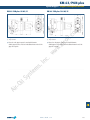

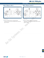


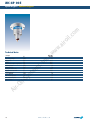
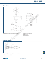


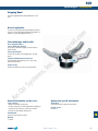

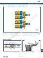
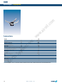
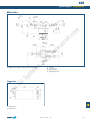

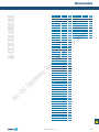


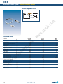


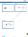


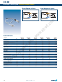

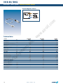


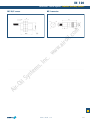
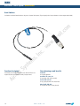


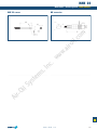
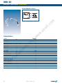

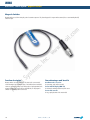

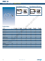
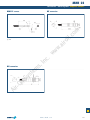


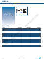


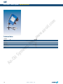
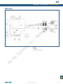


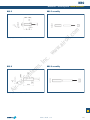

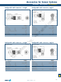
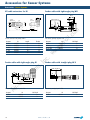
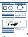


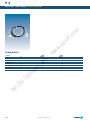
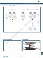
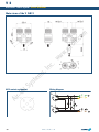


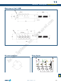
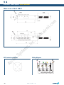


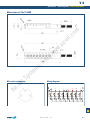
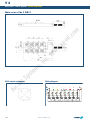


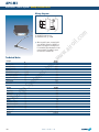


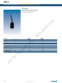
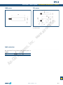


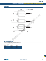
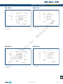


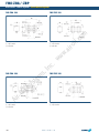
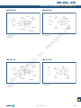


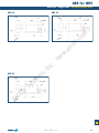
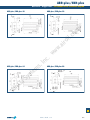

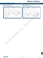


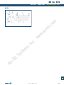

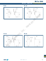


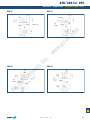


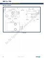


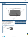

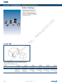
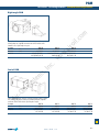


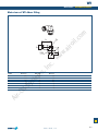
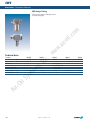
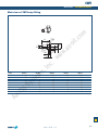


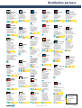

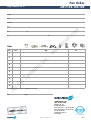
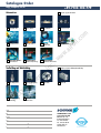


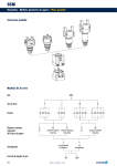


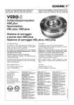
![Referencias y Especificacion Piscinas[...]](http://vs1.manualzilla.com/store/data/006222686_1-80a25bc0fb174e98df902c48fff8528f-150x150.png)