1
VPanel is a program to operate the modeling machine on the computer screen. It has functions to output cutting
data, perform maintenance, and make various corrections. In addition, it displays error messages of the modeling
machine.
VPanel is included in the Roland Software Package CD-ROM, which is supplied with the modeling machine. For
information on how to install it, see "Setup & Maintenance Guide" of the modeling machine.
* You can also use commercial CAM software to output cutting data. For information on compatible CAM software,
contact us or the dealer where you purchased the modeling machine.
For the latest information about this machine (including manuals), see the Roland DG Corp. website (http://www.rolanddg.com).
Contents
Contents....................................................................................................................................... 2
Chapter 1 Basic Operations.............................................................................................................. 3
Displaying or Exiting VPanel........................................................................................................ 4
Displaying VPanel........................................................................................................................................................................... 4
Exiting VPanel.................................................................................................................................................................................. 4
Overview of VPanel Window........................................................................................................ 5
Top Window...................................................................................................................................................................................... 5
Display of VPanel in the Tasktray............................................................................................................................................... 5
Outputting..................................................................................................................................... 6
Outputting Cutting Data............................................................................................................................................................. 6
Quitting Outputting...................................................................................................................................................................... 7
Chapter 2 Details............................................................................................................................... 8
Description of SETTINGS Window.............................................................................................. 9
Settings Tab...................................................................................................................................................................................... 9
Override Tab...................................................................................................................................................................................10
Maintenance Tab..........................................................................................................................................................................11
Correction Tab...............................................................................................................................................................................12
Mail Tab............................................................................................................................................................................................13
Responding to an Error Message.............................................................................................. 14
FAQ (What to Do If…)................................................................................................................ 17
Company names and product names are trademarks or registered trademarks of their respective holders.
Copyright © 2010-2011 Roland DG Corporation
Roland DG Corp. has licensed the MMP technology from the TPL Group.
http://www.rolanddg.com/
Chapter 1
Basic Operations
Displaying or Exiting VPanel...................................................................................4
Displaying VPanel.................................................................................................. 4
Exiting VPanel........................................................................................................ 4
Overview of VPanel Window...................................................................................5
Top Window............................................................................................................ 5
Display of VPanel in the Tasktray........................................................................... 5
Outputting...............................................................................................................6
Outputting Cutting Data.......................................................................................... 6
Quitting Outputting.................................................................................................. 7
3
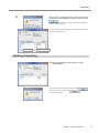
Displaying or Exiting VPanel
Displaying VPanel
Click
tray.
Tasktray
(VPanel icon) in the task-
VPanel will be displayed on the screen. If you
cannot find
in the tasktray, activate it from
the start menu of Windows.
How to start VPanel from the [Start] menu of Windows
From the [Start] menu, click [All programs] (or [Programs]) - [Roland DWX-50] - [VPanel].
VPanel will be activated.
VPanel serves as a resident software.
VPanel works as a resident software which is constantly working to manage the modeling machine and send mails*, and
so on. You are recommended to make settings to enable VPanel to start automatically when the computer starts. ( P.
9 "Settings Tab") When you click
on the upper right corner of the window, the window will disappear from the
screen, but the program will not be terminated. While it is running,
is constantly displayed in the tasktray.
* Mail to notify the completion of cutting or an error when it occurs. ( P. 13 "Mail Tab")
Exiting VPanel
You can exit the program by right-clicking
tasktray, and click [Exit].
Tasktray
4
Chapter 1 Basic Operations
in the
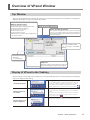
Overview of VPanel Window
Top Window
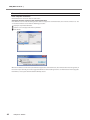
This is the top window of VPanel. It displays the status of the connected modeling machine and output list of cutting data.
Output of cutting data can also be executed by this window.
Machine operation status
Rdy: Cutting data can be received.
Off: The power of the modeling machine is OFF.
Ini: The initial operation is underway.
Bsy: The machine is in operation.
Err: An error has occurred.
Pau: The operation is paused.
* When the front cover is open, "Cov" is displayed next
to the operation status.
Name of connected machine
Status of modeling machine
The operation state, spindle rotation speed, and cutting
time, etc. are displayed. Among the connected machines,
the information of the machine of which the radio button is
checked is displayed.
Displays the SETTINGS window.
P. 9, "Description of SETTINGS
Window"
Used to output and cancel
cutting data.
P. 6, "Outputting"
Output list
Data under cutting and data waiting for cutting are
displayed. The progress of cutting is also displayed.
Display of VPanel in the Tasktray
When the VPanel icon is displayed in the tasktray, the connected modeling machines are always monitored. The following
statuses are displayed in the tasktray.
On/Off of the power
Among the connected modeling machines, if at least
one modeling machine is ON, it is displayed in white. If
no machine is ON, it is displayed in gray. You can check
the machine which is ON by checking the message
which appears when you place the mouse pointer on
Display when an error occurs
Among the connected modeling machines, if an error
occurs on at least one modeling machine, it is displayed
in red.
You can check the machine on which an error occurs by
checking the message which appears when you place
the mouse pointer on
.
The machine of which cutting is completed is displayed.
Display when cutting is completed
Chapter 1 Basic Operations
5
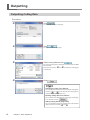
Outputting
Outputting Cutting Data
Procedure
Click
Click
Select cutting data and click
.
The "OUTPUT" window is displayed.
.
The "Open" window is displayed.
.
The selected cutting data is displayed in the data list of the "OUTPUT" window.
Repeat the procedures
and
to output the cutting data
continuously.
Click
.
Changing the order in the data list
You can change the output order by selecting the cutting data
and click
or
in the data list. (The cutting data is
output from the top of the data list.)
Deleting cutting data in the data list
You can delete the cutting data by selecting the cutting data
in the data list and click
.
Adding cutting data by drag & drop
You can add cutting data by drag & drop data on the window
displayed in the procedures
and
.
6
Chapter 1 Basic Operations
Outputting
Check that a workpiece and a tool have been
mounted on the modeling machine, and then click
.
"DWX-50 Operation Guide" ("STEP 1: Mounting a Workpiece,"
"STEP 2: Installing a Tool")
The output cutting data is displayed in the output list of the top
window, and cutting starts.
Cutting data
Progress of output
Quitting Outputting
Click
while cutting data is output.
The message shown in the figure is displayed. Click
when you cancel the output. Click
not cancel the output.
when you do
Chapter 1 Basic Operations
7
Chapter 2
Details
Description of SETTINGS Window.........................................................................9
Settings Tab............................................................................................................ 9
Override Tab......................................................................................................... 10
Maintenance Tab.................................................................................................. 11
Correction Tab...................................................................................................... 12
Mail Tab................................................................................................................ 13
Responding to an Error Message.........................................................................14
FAQ (What to Do If…)...........................................................................................17
8
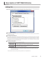
Description of SETTINGS Window
Settings Tab
In this tab, you can make the VPanel auto startup setting and settings related to the NC code, etc. When more than one
machine is connected, the machine selected in the top window is the target of these settings.
Run program at start-up
When a check is put in this checkbox, VPanel is automatically started up at the time when Windows starts up, and VPanel
is displayed in the tasktray.
NC code with decimal point
Select handling and interpretation of the decimal point for NC code. In the case of "Conventional," the unit is interpreted
as millimeter (or inch) when there is a decimal point, and as 1/1000 millimeter (or 1/10000 inch) when there is no decimal
point. In the case of "Calculator," the unit is always interpreted as millimeter (or inch) regardless of whether or not there
is a decimal point. In the case of "Calculator," select the scope of application. Select an appropriate setting according to
your CAM or NC code. (Initial setting: Conventional)
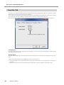
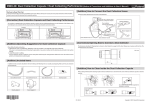
To remove cutting waste
These buttons are used to perform cleaning of the machine.
Every time this button is pressed, movement is done in the order of "Table backward",
"Spindle head right", "Table forward", and "Spindle head left." Whenever the movement
is complete, "Operation was completed" is displayed. Click "OK."
The main clamp rotates by 180 degrees. When the movement is complete, "Operation
was completed" is displayed. Click "OK."
* When the operation button of the built-in panel of the machine is pressed, the spindle head and table
return to the VIEW position (i.e., the left end in the highest position for the spindle head, and the frontmost position for the table).
"Setup & Maintenance Guide" ("Cleaning After Cutting Operation Ends" in "Daily Maintenance").
Chapter 2 Details
9
Description of SETTINGS Window
Override Tab
In this tab, you can adjusut the "Cutting Speed" and "Spindle Speed" during cutting. This is useful when you want to change
the feed rate or speed as you monitor the status of cutting.
An override value is specified as a percentage. For example, when the command in the cutting data sent from the computer
is for a speed of 10,000 rpm, specifying an override of 150% produces an actual speed of 15,000 rpm.
When more than one machine is connected, the machine selected in the top window is the target of these operations.
Clicking these buttons adjusts the values.
Cutting Speed
This works on the tool movement speed of when the workpiece is being cut. The speed specified by the command in the
cutting data is taken to be 100%.
Spindle Speed
This works on the rotation speed of the spindle. The speed specified by the command in the cutting data is taken to be
100%.
When the modeling machine is turned OFF, the override is returned to 100%.
In the top window, not the rotation speed of the spindle after override, but the one specified by the cutting data is
displayed.
Setting an override does not let you perform operation beyond the machine's maximum or minimum speeds.
10
Chapter 2 Details
Description of SETTINGS Window
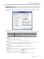
Maintenance Tab
In this tab, you can make the operations related to maintenance, such as auto correction of the modeling machine and
system report. When more than one machine is connected, the machine selected in the top window is the target of these
operations.
Operation
You can make automatic correction ("Correct magazine," "Correct rotary axis") and tool replacement test ("Test tool"). You
should make automatic correction when you install or relocate the machine, or when the cutting position is displaced.
Correct magazine
Correct the position of the ATC magazine.
Correct rotary axis
Correct the position of the rotary axis.
Test tool **
Perform a test to replace the tool.
(** refers to #1 to #5.)
"Setup & Maintenance Guide" ("STEP 2: Automatic Correction" in "Before Starting the Operation").
Spindle
You can check the total working time of the spindle.
"Setup & Maintenance Guide" ("Maintenance of the Spindle Unit" in "Periodic Maintenance").
Run-in
You can perform run-in operation for the spindle. You should use this function when using the machine for the first time
after installation, or after moving the machine and reinstalling it at a different location.
"Setup & Maintenance Guide" ("STEP 1: Spindle Run-in (Warm-up)" in "Before Starting the Operation").
Machine ID
You can set an ID to the machine. You should use this function when connecting more than one machine.
"Setup & Maintenance Guide" ("Connecting Multiple Units").
Diagnosis
You can display the serial number, firmware version, and total operation time, etc. of the machine in a report.
You can save the system report in a text file by clicking
in the System report window.
Error Log
You can display the logs of the errors which have occurred so far.
You can save the system report in a text file by clicking
in the System report window.
Chapter 2 Details
11
Description of SETTINGS Window
Correction Tab
In this tab, you can make corrections of the modeling machine. Perform corrections if you want to precisely adjust the accuracy. When more than one machine is connected, the machine selected in the top window is the target of corrections.
* Perform auto correction before performing this correction.
P. 11, "Maintenance Tab"
Distance (correction of distance in the XYZ direction)
You can correct the moving distance in the X, Y, and Z directions respectively. Set the correction value as considering the
initial moving distance as 100%.
Initial setting: 100%
A axis back side (inversion correction of A axis)
You can correct the angle when the A axis is rotated by 180 degrees. Set the correction value as considering the initial
setting as 0.00 degree.
Initial setting: 0.00 degree
Origin point (correction of the origin)
You can correct the origins of the X, Y, and Z axes, respectively. Set the correction value as considering the initial setting
as 0.00 mm.
Initial setting: 0.00 mm
12
Chapter 2 Details
Responding to an Error Message
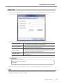
Mail Tab
In this tab, you can make the setting to receive e-mail notifying that cutting is completed or an error has occurred. When
more than one machine is connected, the machine selected in the top window is the target of the setting.
When a check is put in [Send mail], you can enter each item. For information on the input values, see the table below.
Server host name
Mail sending server name (SMTP server name) of the mail software used in the
computer which presently makes the settings of VPanel
Server port number
Mail sending server port number of the mail software used in the computer
which presently makes the settings of VPanel
Sender address
Mail address used in the computer which presently makes the settings of VPanel
(It is a mail sender address. It must be a mail address from which mail can be
sent to the mail sending server explained above.)
Receiver address
Mail address of a mail receiver. You can input more than one address by separating with comma.
Click
to perform the sending test. If the mail with the following data arrives at the address specified in "Receiver address," the setting is complete.
Subject : <Name of the machine>
Text : TEST
When a mail failed to be sent, the "Windows Script Host" error window is displayed. Check the input items again.
Note
If using a server that requires user authentication and/or encipher, a mail cannot be sent. Use a transmission server that does
not require user authentication and/or encipher.
Chapter 2 Details
13
Responding to an Error Message
This section describes the error messages that may appear on VPanel window, and how to take action to remedy the problem. If the action described here does not correct the problem, or if an error message not described here appears, contact
your authorized Roland DG Corp. dealer.
* Remedies of problems are also explained in "What to Do If ..." in "Setup & Maintenance Guide."
[ERROR OCCURRED] : The tool has not been released.
The spindle unit seizes the tool and does not release it. Release the tool forcibly by following the message.
[ERROR OCCURRED] : The tool might be broken.
The tool might be broken. Stop the operation of the modeling machine and check the tool.
[ERROR OCCURRED] : The tool is too long (short).
The tool is too long or too short. Stop the operation of the modeling machine and set the tool with an appropriate length
(40 to 55 mm). There is a possibility that the position of the tool holder is not correct. Check the position of the tool holder.
"DWX-50 Operation Guide" ("STEP 2: Installing a Tool" in "Starting Cutting")
[ERROR OCCURRED] : The tool is not found.
The ATC magazine failed to seize the tool. The tool is not set, or it is mounted on a wrong stocker number. Set the tool again.
Click "Retry" in the displayed message, and the operation is resumed. When you click "Quit," the modeling machine stops
operation.
[ERROR OCCURRED] : The tool chucking has slipped out.
The tool is displaced from the collet and is about to fall. Stop cutting, check the cutting conditions, etc., and restart it from
the beginning.
14
Chapter 2 Details
Responding to an Error Message
[ERROR OCCURRED] : The number of parameters for a RML-1 command received from the computer was incorrect.
[ERROR OCCURRED] : The parameter for a RML-1 command received from the computer was out of range.
[ERROR OCCURRED] : The RML-1 command from the computer could not be interpreted.
The operation was paused because the cutting data received from the computer was not correct, and it resulted in an error.
Stop the operation of the modeling machine and check the cutting data. Then restart the operation from the beginning.
[ERROR OCCURRED] : NC code error occurred. Address is not defined.
[ERROR OCCURRED] : NC code error occurred. Parameter is not defined.
[ERROR OCCURRED] : NC code error occurred. Can not be executed.
The operation was paused because an error related to the NC code has occurred. Stop the operation of the modeling machine
and check the cutting data. Then restart the operation from the beginning.
[ERROR OCCURRED] : % motor position is lost.
(% is any of "X", "Y", "Z", "A", or "B".)
Position displacement has occurred during cutting. Stop cutting, check the cutting conditions, etc., and restart it from the
beginning.
[EMERGENCY STOP] : Cover opened during operation.
A front cover was opened during cutting or spindle rotation. Turn off the power, and close the front cover, and then restart
the operation from the beginning.
[EMERGENCY STOP] : The spindle experienced an excessive load.
[EMERGENCY STOP] : The spindle experienced excessive current of electricity.
[EMERGENCY STOP] : The spindle control circuit temperature is high.
[EMERGENCY STOP] : The spindle motor temperature is high.
A spindle-motor error occurred. This is caused by prolonged high load on the motor or by excessive torque being applied
momentarily. Turn off the power. The cutting may have exceeded the capacity of the machine. Before restarting, revise the
cutting conditions. Also, allow the machine to rest for some time, because the motor may have overheated. If messages like
these persist, contact your authorized Roland DG Corp. dealer.
Chapter 2 Details
15
Responding to an Error Message
[EMERGENCY STOP] : Spindle rotation is impossible because the spindle shaft is locked or voltage is too low.
An emergency stop occurred because the spindle cannot be rotated. Possible causes include the spindle shaft being frozen
by accumulated cutting waste or the like, or a drop in voltage due to excess load on the spindle. Turn off the power, make
sure no obstruction is impeding the operation of the spindle head, and take steps such as revising the cutting conditions as
needed. The motor may also have overheated, so allow the machine to rest for some time before restarting. If messages like
these still continue to appear, turn off the power and contact your authorized Roland DG Corp. dealer.
[EMERGENCY STOP] : A broken connection or other damage occurred between the spindle control circuit and the motor.
[EMERGENCY STOP] : A communication error occurred in the spindle control firmware.
[EMERGENCY STOP] : The spindle control firmware is inoperative.
An emergency stop occurred because of a error in spindle control. Turn off the power and restart the machine. If this message
persists, turn off the power and contact your authorized Roland DG Corp. dealer.
[EMERGENCY STOP] : The chucking motor experienced excessive current.
[EMERGENCY STOP] : The chucking motor control circuit experienced excessive current.
Overcurrent flew through the chucking motor drive circuit due to overload. Turn off the power and restart the machine. If
this message persists, turn off the power and contact your authorized Roland DG Corp. dealer.
[EMERGENCY STOP] : % limit switch is not found.
(% is any of "X", "Y", "Z", "A", or "B".)
The limit switch of the displayed axis cannot be detected. Turn off the power, remove the objects which block the operation
of the machine and accumulated cutting waste, if any, and then restart the machine. If this message persists, turn off the
power and contact your authorized Roland DG Corp. dealer.
16
Chapter 2 Details
FAQ (What to Do If…)
* Remedies for problems are also explained in "What to Do If ..." in "Setup & Maintenance Guide."
VPanel doesn't start correctly./Output cannot be made on VPanel.
Is the computer connected?
Check whether the connector cable has come loose.
Is the driver installed correctly?
If the connection to the computer is not made in the sequence described, the driver may fail to be installed correctly. VPanel
does not function normally when driver is misconfigured. Check again to ensure that the connection was made using the
correct procedure.
"Setup & Maintenance Guide" ("Installing the Windows-based Driver" in "Installing and Setting Up the Software")
When more than one machine is connected, are the machine connected properly according to the connection method?
There is a possibility that the connection method might be incorrect when more than one machine is connected. Check the
correct connection method.
"Setup & Maintenance Guide" ("Connecting Multiple Units").
The detection of the ATC magazine or rotary axis failed.
Is the main clamp, detection pin, or ATC magazine contaminated?
Remove contamination on the main clamp, detection pin, or ATC magazine if any. If they are contaminated due to buildup
of cutting waste or the like, the sensor cannot operate correctly, making correct detection impossible.
"Setup & Maintenance Guide" ("Chapter 2 Maintenance")
Does the cover and/or cap of the dust collection capsule remain attached?
Remove the cover and cap of the dust collection capsule when you make a correction of the rotary axis.
Replacement of the tool failed.
Is the tool installed correctly?
Check the mounting position of the tool holder, or the length and diameter of the tool.
"DWX-50 Operation Guide" ("STEP 2: Installing a Tool" in "Starting Cutting")
Perform auto correction.
The position of the ATC magazine might be displaced. Perform auto correction.
P. 11 "Maintenance Tab"
Is the ATC magazine contaminated?
Remove contamination on the ATC magazine if any. If the ATC magazine is contaminated due to buildup of cutting waste
or the like, you may fail the tool replacement.
"Setup & Maintenance Guide" ("Chapter 2 Maintenance")
The cutting results are not attractive / The cutting position is displaced
Perform auto correction (correction).
Perform auto correction of the rotary axis.
P. 11 "Maintenance Tab"
You can precisely correct the moving distance in the X, Y, and Z axes and the angle of the A axis, etc.
P. 12 "Correction Tab"
Is the workpiece securely mounted in place?
Check the mounting state of the workpiece. Fasten the workpiece in place securely so that the workpiece will not slip out of
place or come off because of vibration during cutting or tool pressure.
"DWX-50 Operation Guide" ("STEP 1: Mounting a Workpiece" in "Starting Cutting")
Is the tool tip worn?
If the tip of the tool is worn, replace with a new tool.
Chapter 2 Details
17
FAQ (What to Do If…)
The override cannot be set.
Is the computer connected?
Check whether the connector cable has come loose.
Check the firmware version of the modeling machine.
If the firmware version of the modeling machine does not support the override function, the override cannot be set. You
can check the firmware version with the following procedure.
Display the top window of VPanel.
Click the icon in the upper left of the top window.
Click “About”.
When the “Firmware” is “V140” or later, the firmware supports the override function. (The numerals after “B” can be ignored.) If
the version is prior to V140, you need to upgrade the firmware of the modeling machine. For information on how to upgrade
the firmware, contact your authorized Roland DG Corp. dealer.
18
Chapter 2 Details
DOC-0897
R4-111226