1
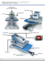
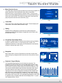
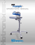
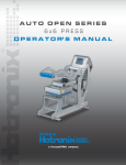
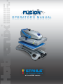
O P E R A T O R’ S M A N U A L
Safety Instructions
When using your heat press,
basic precautions should always be followed,
including the following:
1.
Read all instructions.
2.
Use heat press only for its intended use.
3.
To reduce the risk of electric shock, do not immerse the heat press in water or other liquids.
4.
Never pull cord to disconnect from outlet, instead grasp plug and pull to disconnect.
5.
Do not allow cord to touch hot surfaces, allow heat press to cool completely before storing.
6.
Do not operate heat press with a damaged cord, or if the equipment has been dropped or
damaged. To reduce the risk of electric shock, do not disassemble or attempt to repair the heat
press, take it to a qualified service person for examination and repair. Incorrect reassembly or
repair could cause a risk of fire, electric shock, or injury to persons when the equipment is used.
7.
Close supervision is necessary for any heat press being used by or near children. Do not leave
equipment unattended while connected.
8.
Burns can occur when touching hot metal parts.
9.
To reduce the likelihood of circuit overload, do not operate other high voltage equipment on the
same circuit.
10.
If an extension cord is necessary, then a 20 amperage rated cord should be used. Cords rated for
less amperage may overheat, care should be taken to arrange the cord so that it cannot be pulled
or tripped over.
SAVE THESE INSTRUCTIONS
®
™
HOTRONIX
FUSION
Ta b l e o f C o n t e n t s
Safety Instructions
2
Machine View
4
Touch Screen Guide
5
Operating Instructions
Connecting the System
Start Up/Shut Down
Operation Screen
Main Menu
Passwords
Setup Menu
Display Setup
Auto On/Off Setup
Presets Setup
Printing Pressing
Replacement Parts List and Location Guide
6-15
6
7
8
9
10
11-14
11-12
12
13-14
15
16-17
Electrical Schematic
18
Contact
19
3
®
™
HOTRONIX
FUSION
Machine View
Over-the-Center
Pressure Adjustment Knob
Touch Screen
Swing Handle
IEC Inlet
Heat Platen
Circuit Breaker
Power ON/OFF Switch
Lift Handle
ON
OFF
Lower Platen
Swing Lock
Base
4
Pull Handle
®
™
HOTRONIX
FUSION
To u c h S c r e e n G u i d e
Menu Selection Screen
Main Menu
A scrollable Menu Selection screen provides a quick and easy navigation to
system operations. Use the Up/Down arrow buttons on the Menu
Selection Screen to scroll through the available menus. The large menu
button in the middle displays the selected menu. Press this Menu Button to
choose the menu selection. The smaller top and bottom menu button displays the previous and next menu selections. (Fig.1)
Operation
Shutdown
Setup
3/19/10 1:22 PM
Fig.1
Control Bar
Each screen has a control bar display at the bottom. This bar displays the
current Date, Time and the Stahls’ Hotronix® logo.
ENTER PASSWORD
Editing
CANCEL
Editable fields are displayed as text boxes with a white background.
Selecting an editable field will display a Keypad that can be used to edit
the field value. (Fig.2)
3/19/10 1:23 PM
Fig.2
Override : 8s, 10s, 320F, 5PR
Increasing / Decreasing Values
In addition to editable fields, an Up/Down arrow button may be provided to
increase or decrease values, or scroll through a list of values. The
Up/Down arrow button (in most cases) can be held down to automatically
increase or decrease the value. (Fig.3)
329
330F
5S
F
5PR
Counter : 0
Main Menu
3/19/10 1:24 PM
Fig.3
Navigation
Most screens have a Cancel or Back button to close the current screen
without saving any changes and will return the user to the previous screen.
(Fig. 4)
Preset Setup
Preset Name :
New Preset 1
New Preset 2
New Preset 1
8 s Temperature 1 : 330 F
Timer 1 :
Timer 2 :
10 s Temperature 2 :
Timer 3 :
0 s
Timer 4 :
0 s Pressure :
0 F
5
Temperature :
Keyboard / Keypad Display
The Keyboard/Keypad display is used for data entry purposes. The
Keypad can be used to enter text or numeric data when required. It also
provides function keys for Cancel, Enter, and Backspace/Clear (“<”) keys.
Also a mode key may be present between the Cancel and Enter key. The
mode key can switch between upper and lower case letters and numeric
and other characters that maybe entered using the Keyboard/Keypad.
Typically the current value is displayed in the Keypad value display at the
top of the screen. Use the Keypad to change the current value. Use the
Enter key to accept the change or the Cancel key to exit without accepting
the change to the current value. The Keyboard/Keypad display is also used
for password entry. Password characters will be displayed with “*” in place
of the password value. (Fig.5)
BACK
NEW
F
DELETE
3/19/10 1:25 PM
Fig.4
A
B
C
D
E
F
G
H
I
J
K
L
M
N
O
P
Q
R
S
T
U
V
W
X
Y
Z
CANCEL
a-z
<
ENTER
3/19/10 1:26 PM
Fig.5
5
®
™
HOTRONIX
FUSION
Operating Instructions
HOTRONIX® FUSION™
The Hotronix® Fusion™ Operating Instructions are designed with the user in mind. Carefully read and follow the
step-by-step instructions for best results.
To avoid burns, do not touch the heated platen
during use.
Keep hands clear of the upper platen of the press
during platen lock down as the pressure may
cause injury.
Press should be placed on a sturdy, suitable stand
at least 36″L x 24″W x 29″H.
Work area must be kept clean, tidy and free of
obstructions.
Power supply cord must be disconnected before
cleaning or servicing press.
Connecting the System
1.
Connect the power cord into the IEC inlet located in the back of the Press. (1.1)
Connect the opposite end of the cord into a properly grounded electrical outlet with a sufficient amperage rating.
Voltage
120 Volt - The Hotronix® Fusion™ requires a full 20 amp grounded circuit for
120 volt operation.
240 Volt - The Hotronix® Fusion™ requires a full 10 amp grounded circuit for
240 volt operation.
Extension Cords
If used, extension cords should be as short as possible and not less than
12 gauge. Heavy duty cords are recommended.
1.1
Circuits
Circuits that have less than 15 amps or that have other high demand equipment or appliances
(especially more than one heat seal machine) plugged in, should not be used.
Note: If the supply cord is damaged, it must be replaced by the manufacturer, its service agent or a similarly qualified
person in order to avoid hazard. Use HSJ type, rated 250 V - 10 AMP for replacement.
CAUTION Failure to follow these instructions will cause:
1. Erratic controller functions.
6
2. Inaccurate displays and slow heat-up.
3. The circuit breaker to disengage.
HOTRONIX® FUSION™
Start Up
2.
To start up your Fusion™ Press:
Flip the Power switch to the “On”
position. (The power switch is
located on the top of the control
housing). (2.1) During the startup,
a splash screen is shown for
approximately 3 seconds. This
screen displays the Hotronix® logo
and current software version
information. (2.2)
2.1
Version : 1.0 X7
2.2
Shut Down
3.
To shut down your Fusion™ Press:
New Preset 1 : 8s, 10s, 330F, 5PR
330
5PR
Main Menu
330F
5S
F
Counter : 1
3/19/10 1:27 PM
190
F
Select the “Main Menu” button in
the operation screen. (3.1)
Then select the “Shutdown”.
function in the Main Menu or flip
the power switch to the off position.
(3.2)
Main Menu
Operation
Shutdown
Setup
3/19/10 1:28 PM
When the heat platen is above
100°F (38°C), the current platen
temperature is displayed on a
orange background as a warning
of the current platen temperature.
(3.3)
3.3
3.4
Note: During this time, the Shutdown operation can be exited by simply pressing the touch screen. The Dream Board
will exit the Shutdown screen and return to the Main Menu.
Once the platen has cooled below 100° F (38° C), the touch screen will go blank. (3.4)
7
HOTRONIX® FUSION™
Operation Screen
4.
The Operation Screen is the first screen displayed after the splash screen and start up has completed. This screen
provides all the printing functions.
Presets
Saved Presets are displayed at the top of the Operation screen. Presets
can be selected using the Left and/or Right arrow keys at the top left and
right corners of the screen. Only the left arrow key is displayed when
only one Preset is present. The Preset displays the Time1(s), Time 2(s),
Temperature(F) and Pressure(PR). (4.1)
The example shown depicts a Preset with the name of “New Preset 1”, a
first timer of 8 seconds, a second timer of 10 seconds, and a temperature
of 330°F using a platen pressure of 5. (4.1)
New Preset 1 : 8s, 10s, 330F, 5PR
330
5PR
Main Menu
F
330F
5S
Counter : 0
3/19/10 1:29 PM
Actual Readings
The Actual Temperature and Pressure readings are displayed on the left
side of the Operation screen. These are the current Heat Press readings.
(4.2)
Target Settings
Target Temperature and Timer settings are displayed on the right side of
the screen. These settings may be overridden. (4.2)
To change these settings, select the Target Temperature and/or Timer
display and adjustment Up/Down arrows will be displayed. Use the
Up/Down adjustment arrows to change the Target Temperature and/or
Timer. (4.3)
The Preset display name at the top of the screen will change to “Override”
to indicate the Preset has been manually changed. (4.3)
Note: During the print process, the Target Timer setting will change to
display a count down timer showing the remaining time on the printing
process.
New Preset 1 : 8s, 10s, 330F, 5PR
330
5PR
Main Menu
F
330F
8S
Counter : 0
3/19/10 1:30 PM
Override : 8s, 10s, 320F, 5PR
326
5PR
Main Menu
F
320F
8S
Counter : 0
3/19/10 1:31 PM
Job Counter
A Job Counter is displayed in the bottom middle of the screen. The Job
Counter counts the total number of complete print cycles performed using
the current Preset or Override settings. Exiting the Operation screen or
changing the Preset will reset the Job Counter to 0. Changing an Override
setting does not reset the Job Counter to 0. (4.4)
Main Menu Button
Use the Main Menu button to exit the Operation screen and proceed to the
Main Menu. (4.4)
8
Override : 8s, 10s, 330F, 5PR
320
5PR
Main Menu
F
320F
10S
Counter : 1
3/19/10 1:32 PM
HOTRONIX® FUSION™
Main Menu
5.
The Main Menu provides access functions of the Fusion™ product. The available menus are:
Shutdown, Setup, About, and Operation.
Main Menu
Select the “Operation” Menu to exit
the Main Menu and return to the
Operation screen. (5.1, 5.2)
About
Operation
New Preset 1 : 8s, 10s, 330F, 5PR
330
5PR
Shutdown
Main Menu
330F
5S
F
Counter : 1
3/19/10 1:32 PM
3/19/10 1:32 PM
5.1
5.2
Main Menu
Setup
About
Operation
3/19/10 1:33 PM
5.3
Select the “About” Menu to display
the Splash Screen. The Splash
screen is displayed for
approximately 3 seconds and
returns to the Main Menu
selection screen. This menu is
useful for displaying the current
software version and production
information. (5.3, 5.4)
The “Setup” Menu selection screen
provides additional system setup
functions not accessible from the
Main Menu. Those functions are:
Presets, Display, Auto On/Off, and
Main Menu. (5.5, 5.6)
Main Menu
Shutdown
Setup
About
Version : 1.0 X7
5.4
Setup Menu
Auto On/Off
Main Menu
Presets
3/19/10 1:34 PM
3/19/10 1:34 PM
5.5
5.6
Note: A Password is required to access the Setup menu. (refer to pgs 10 -11 for Login information)
Main Menu
Press the “Shutdown” menu to exit
The Fusion™. (5.7, 5.8)
Operation
See page 7 for further details.
Shutdown
Setup
3/19/10 1:34 PM
5.7
5.8
9
HOTRONIX® FUSION™
Passwords
6.
A password is required to access the Setup Menu and configure certain functions of the Hotronix® Fusion™.
Main Menu
In the Main Menu, press the
“Setup” Menu. (6.1)
Shutdown
ENTER PASSWORD
Then press the blank password
field. (6.2)
Setup
CANCEL
About
3/19/10 1:35 PM
3/19/10 1:36 PM
6.2
6.1
A
B
C
D
E
F
G
H
I
J
K
L
M
N
O
P
Q
R
S
T
U
V
W
X
Y
Z
CANCEL
a-z
<
ENTER
A Keyboard/Keypad will be
displayed. (6.3)
Enter the letter “U” for a “User
Level” password and press Enter
when complete. (6.4)
*_
A
B
C
D
E
F
G
H
I
J
K
L
M
N
O
P
Q
R
S
T
U
V
W
X
Y
Z
CANCEL
a-z
3/19/10 1:36 PM
3/19/10 1:37 PM
6.4
6.3
*_
A
B
C
D
E
F
G
H
I
J
K
L
M
N
O
P
Q
R
S
T
U
V
W
X
Y
Z
CANCEL
a-z
<
ENTER
3/19/10 1:38 PM
Note: You can Select the Cancel
button to exit the Password Entry
screen and return to the previous
screen at any time. (6.5)
If an invalid password is entered,
select the blank password field and
repeat the previous step. (6.6)
INVALID PASSWORD!
ENTER PASSWORD
*
CANCEL
3/19/10 1:38 PM
6.6
6.5
Setup Menu
Now you will be automatically
entered into the Setup Menu where
you will have full access to all
Setup functions. (6.7)
Auto On/Off
Main Menu
Presets
Setup Menu
Presets
Display
Auto On/Off
3/19/10 1:38 PM
6.7
10
<
ENTER
3/19/10 1:40 PM
6.8
™
HOTRONIXS® eFUSION
tup Menu
Display Setup
7.
The Hotronix® Fusion™ functions and features can be configured using the Setup menu. These features include:
Presets, Display, Auto On/Off, and Main Menu.
After your password is entered in the setup menu, scroll down and select
the “Display” button. (6.8)
This option will allow you to configure the Temperature Units, Pressure
Units, Display Language and to set the Date and Time. (7.1)
Display Setup
Units
Temperature :
F
PSI
Pressure :
Month :
Year :
Hour :
Language
Date & Time
Day :
19
Minute :
25
03
2010
01
PM
BACK
3/19/10 1:40 PM
7.1
Temperature Units
The Temperature Units can be changed from F (Fahrenheit) to C (Celsius).
This is a global setting and Temperature values will be displayed in the
configured units. Select the Temperature Units button to toggle between
“F” and “C.” Press the Save button to save any changes. (7.2)
Note: You will lose any changes if you leave the Setup Menu without
pressing the “Save” button. You can also use the “Back” or “Cancel”
buttons on Setup Screens to exit the screen and return to the previous
screen.
Temperature :
C
PSI
Pressure :
Month :
Year :
Hour :
Language
Date & Time
Day :
19
Minute :
25
03
2010
01
PM
BACK
SAVE
3/19/10 1:42 PM
7.2
Pressure Units
The Pressure Units can be changed from PSI (Pressure per Square Inch)
to kPa (kilopascals). Select the Pressure Units button to toggle between
PSI and kPa. These are your global pressure settings that will be displayed
in the configured units. Press the Save button to save any changes. (7.3)
Display Setup
Units
Display Setup
Units
Temperature :
Pressure :
C
kPa
Month :
Year :
Hour :
Language
Date & Time
Day :
19
Minute :
25
03
2010
01
PM
BACK
SAVE
3/19/10 1:43 PM
7.3
Language
To change the display Language, select the Language button. The
Language selection screen will be displayed. Use the Up/Down arrows
to scroll through the available languages. Once the desired language is
selected, press the “Save” button. (7.4)
Note: Changing and Saving the Language setting requires a restart of the
Fusion™. The machine will automatically restart and return to the Operation
screen using the new Language display settings.
Select Language
English
Deutsch
Espanol
Francais
CANCEL
SAVE
Please refer to page 12 to configure the Date and Time.
3/19/10 1:44 PM
7.4
11
®
™
HOTRONIX
FUSION
Setup Menu
Display Setup
Date and Time
To set the Date and Time, select the individual numeric display for the
Month, Day and Year. A numeric Keyboard/Keypad will be displayed. (7.5)
Change the numeric value using the Keypad, then press “Enter” to save
any changes.
Repeat the same process to set the Hour and Minute.
04_
1
2
3
8
9
0
4
5
6
7
<
CANCEL
ENTER
3/19/10 1:29 PM
7.5
To change the AM/PM designator, select the AM/PM button to toggle
between the AM/PM settings. (7.6)
Press the Save button to save the new Date and Time settings.
Display Setup
Units
Temperature :
Pressure :
C
kPa
Month :
Year :
Hour :
Note: It may take a few seconds for the Date and Time display to update
on the Control Bar at the bottom of the screen.
Day :
02
Minute :
45
04
2010
01
Language
Date & Time
AM
BACK
SAVE
3/19/10 1:45 PM
Select the back button to return to the Setup menu. (7.6)
7.6
Auto On/Off Setup
8.
The system can turn On or Off automatically when configured. The Auto On/Off feature is configured for each day
of the week.
In the Setup Menu, Select the Auto On/Off Button. To configure an Auto
On/Off setting, use the Up/Down selection arrows to select the day of the
week to be configured. Use the Enable/Disable button to enable that day
of the week setting. (8.1)
Note: Each day that you want the system to automatically turn On/Off,
must be Enabled.
Automatic On and Off Setup
Sunday
Monday
Tuesday
Wednesday
Thursday
Auto On
12
:
00
AM
Auto Off
12
:
00
PM
Disabled
BACK
3/19/10 1:47 PM
8.1
When enabled, set the time of day for Auto On and Off events by selecting
the Hour and Minute fields. (8.2) Using the displayed Keyboard/Keypad,
enter the numeric time values and press enter.
Use the AM/PM designator button to toggle between the AM or PM
settings. Select the Save button to save the settings. (8.2)
Note: Selecting another day of the week or exiting the Auto On/Off Setup
screen without saving will result in loss of changes.
12
Automatic On and Off Setup
Sunday
Monday
Tuesday
Wednesday
Thursday
Auto On
07
:
00
AM
Auto Off
03
:
30
PM
Enabled
BACK
SAVE
3/19/10 1:48 PM
8.2
™
HOTRONIXS® eFUSION
tup Menu
Presets Setup
9.
Presets are configured using the Preset Setup screen. A Preset can have 1 - 4 Timer values, 2 Temperature values,
1 Platen Pressure setting, and a descriptive Name.
Setup Menu
In the Setup Menu, Select the
“Presets” button. (9.1)
Main Menu
Use the Up/Down arrows to scroll
through the list of Presets and
select a Preset for editing. (9.2)
Presets
Display
Preset Setup
Preset Name :
New Preset 1
8 s Temperature 1 : 330 F
Timer 1 :
New Preset 1
New Preset 2
Timer 2 :
10 s Temperature 2 :
Timer 3 :
0 s
Timer 4 :
0 s Pressure :
0 F
5
Temperature :
BACK
NEW
3/19/10 1:50 PM
F
DELETE
3/19/10 1:51 PM
9.1
9.2
Preset Setup
Preset Name
Preset Name :
A descriptive name for identifying a Preset, limited to 20 characters in
length. A Preset Name can be added to the Preset list by selecting the
“New” button. (9.3)
New Preset 1
8 s Temperature 1 : 330 F
Timer 1 :
New Preset 1
New Preset 2
Timer 2 :
10 s Temperature 2 :
Timer 3 :
0 s
Timer 4 :
0 s Pressure :
0 F
5
Temperature :
BACK
NEW
F
DELETE
3/19/10 1:53 PM
9.3
Preset Setup
Preset Name :
New Preset 1
New Preset 2
8 s Temperature 1 : 330 F
Timer 1 :
Timer 2 :
New Preset 1
10 s Temperature 2 :
Timer 3 :
0 s
Timer 4 :
0 s Pressure :
5
Temperature :
BACK
NEW
0 F
F
Enter a Preset Name by pressing
the “Preset Name” field. (9.4)
A keyboard/Keypad will be
displayed. Name the Preset and
press “Enter.” (9.5)
DELETE
New Preset 3_
a
b
c
d
e
f
g
h
i
j
k
l
m
n
o
p
q
r
s
t
u
v
w
x
y
z
CANCEL
A-Z
3/19/10 1:56 PM
3/19/10 1:54 PM
9.5
9.4
Press the “Save” button to save the new Preset. (9.6)
Note: The new Preset must be Saved before it can be displayed in the
list. Also, any changes to a Preset must be Saved before selecting a new
Preset in the list and before exiting the Preset Setup screen or any
changes will be lost.
Press the Delete button if you wish to remove any selected Preset from
the list. (9.6)
Note: this function cannot be undone.
<
ENTER
Preset Setup
Preset Name :
New Preset 1
New Preset 2
New Preset 3
Timer 2 :
New Preset 3
8 s Temperature 1 : 330 F
Timer 1 :
10 s Temperature 2 :
Timer 3 :
0 s
Timer 4 :
0 s Pressure :
5
Temperature :
BACK
SAVE
NEW
0 F
F
DELETE
3/19/10 1:58 PM
9.6
13
®
™
HOTRONIX
FUSION
Setup Menu
Presets Setup
Timer
Timers can be set using values 0 – 999 seconds. Entering a value of 0 seconds disables a Timer and it will not be
used or displayed in the Preset selection on the Operation screen.
Preset Setup
Preset Name :
New Preset 1
New Preset 2
New Preset 3
New Preset 3
Timer 1 :
10
s
Temperature 1 : 330 F
Timer 2 :
15
s
Temperature 2 :
Timer 3 :
0
s
Timer 4 :
0
s
5
Pressure :
Temperature :
BACK
NEW
0 F
Select the “Timer” field (Timer 1,2,3
or 4) to open a Keyboard/Keypad
to change the Timer setting. (9.7)
Select the desired time and press
“Enter”. (9.8)
F
DELETE
08_
1
2
3
8
9
0
4
5
6
7
<
CANCEL
ENTER
3/19/10 2:00 PM
3/19/10 2:02 PM
9.7
9.8
Temperature
Temperatures can be set from 32°F - 430°F (0° - 221°C). Setting a Temperature value to 0 (Fahrenheit) disables the
Temperature setting. Select the Temperature field to open a Keyboard/Keypad to change the Temperature settings.
(9.9)
Preset Setup
Preset Name :
New Preset 1
New Preset 2
New Preset 3
New Preset 3
Timer 1 :
10
s
Temperature 1 : 330 F
Timer 2 :
15
s
Temperature 2 :
Timer 3 :
0
s
Timer 4 :
0
s
NEW
310_
1
2
3
8
9
0
4
5
6
5
Pressure :
Temperature :
BACK
0 F
Use the Temperature F or C button
to toggle the Temperature units for
display and/or entry between
Fahrenheit and Celsius. (9.9)
Select the desired temperature and
press “Enter”. (9.10)
F
DELETE
7
<
CANCEL
ENTER
3/19/10 2:05 PM
3/19/10 2:03 PM
9.9
9.10
Pressure
This is the recommended Preset Platen Pressure setting. This has a valid range of 0 - 9. A “0” Pressure readout would
indicate no pressure at all and “9” would indicate very heavy pressure.
Preset Setup
Preset Name :
New Preset 1
New Preset 2
New Preset 3
New Preset 3
Timer 1 :
10
s
Temperature 1 : 310 F
Timer 2 :
15
s
Temperature 2 :
Timer 3 :
0
s
Timer 4 :
0
s
5
Pressure :
Temperature :
BACK
NEW
0 F
F
DELETE
Select the Pressure field to display
a Keyboard/Keypad for editing this
value. (9.11,)
Select the desired pressure and
press “Enter.” (9.12)
6_
1
2
3
8
9
0
4
14
6
7
<
CANCEL
ENTER
3/19/10 2:06 PM
9.11
5
3/19/10 2:07 PM
9.12
HOTRONIX® FUSION™
Printing / Pressing
10. Prepare to Print
To begin Printing / Pressing, go to the Main Menu and select “Operation” to enter the Operation screen. (10.1)
Note: Be sure you have the correct Preset selected for your application.
Main Menu
You may also manually adjust your
desired Time, Temperature and
Pressure settings (refer to pg 8).
About
Operation
Shutdown
3/19/10 2:08 PM
Note: Be sure the Actual press
Temperature has reached the
Target Temperature, (10.2)
New Preset 1 : 8s, 10s, 330F, 5PR
330
5PR
Main Menu
F
330F
5S
Counter : 1
3/19/10 2:10 PM
10.1
10.2
When the desired settings are reached you may begin to Print / Press.
When using the “Swing” feature:
Swing the heat platen out and
position the garment and
application. (10.3)
When using the “Draw” feature:
Pull out the lower platen and
position the garment and
application. (10.4)
10.3
10.4
Swing the heat platen or push the lower platen back into position. Then lower the heat platen into the press position.
The Timer display will automatically initiate a count down and visually and
audibly signal you when to lift the platen off the garment. Immediately lift
the platen to the UP position. (10.5)
Swing the heat platen or pull the lower platen away and proceed
according to your application’s instructions.
New Preset 1 : 8s, 10s, 330F, 5PR
330
5PR
Main Menu
Your equipment has automatically reset and you may continue to
Print / Press.
F
330F
1S
Counter : 1
3/19/10 2:10 PM
10.5
15
®
™
HOTRONIX
FUSION
Replacement Parts List
Item #
1
2
3
4
5
6
7
8
9
10
11
12
13
14
15
16
17
18
19
20
21
22
23
24
25
26
27
28
29
30
31
32
33
34
35
36
37
38
39
40
41
42
43
44
45
46
47
48
49
50
51
52
53
54
55
16
Part Name
Base Assembly
Rubber Foot
Right Upper Link
Low Profile SHCS
Stop Collar
Hex Nut
Hand Retractable Plunger
Steel Pin
Upper Casting
Washer
Castle Nut
Adjustment Casting
E-Clip
Steel Shim
Adjustment Spindle
Adjustment Knob
Spherical Washer
Ball Plunger
Roll Pin
Swing Knob
Lift Rod Bushing
Left Upper Link
Guide Tube
Undercarriage
Handle Spacer
Foam Grip
Lift Link
Clevis Pin
Nylon Lock Nut
Screw, Cap But Hd. 3/8-16 x ¾″
Inner Lift Arm (Thick)
Bearing
Outer Lift Arm (Thin)
C-Frame
Slide Rail
Draw Tray
Compression Spring
Nylon Washer
Shoulder Bolt
Draw Handle
Quick Change Pin
Adaptor Plate
Lower Platen
Silicone Pad 16″x20″ (Blue)
Heat Platen (16″x20″)
Heater Cover
Finish Washer
Cover Screw
Touch Screen Controller
Control Housing Overlay
Control Housing
Power Switch
Breaker
IEC Inlet
Power Coard
Part #
Qty.
4-1175
1-2199
Kit 3-6929
3-1011-245
1-2203
2-1006-93
1-2206
1-2204
2-1664
2-1006-21
2-1006-1
1-2162
1-1019-1
1-2217
1-1010-2
1-1012
2-1006-92
1-2201
1-1018-1
1-1054
1-1013
Kit 3-6929
1-2194
Kit 3-6911
0175-12
1-2116
1-1024
1-1017-1
2-1006-20
3-1011-244
1-2207
1-1300
1-2208
3-1335
1-1749
1-2164
1-2195
2-1006-65
3-1011-121
1-2182
1-2215
3-1336
2-1029
1-2136
2-1002
1-2189
1-1063
3-1011-217
1-2167
1-2198
1-2197
1-2087
1-1331
1-1759
2-1013-1
1
4
1
2
1
1
2
1
1
1
1
1
1
1
1
1
1
1
2
1
1
1
1
1
1
1
2
2
2
3
2
2
2
1
2
1
6
6
6
1
1
1
1
1
1
1
4
4
1
1
1
1
1
1
1
®
™
HOTRONIX
FUSION
Parts Location Guide
52
53
55
54
51
17
16
15
14
13
50
12
18
19
11
20
49
10
21
48
9
22
8
47
7
23
46
6
24
45
5
44
43
3
25
26
42
41
34
27
28
29
4
33
30 31
32
35
40
39
2
38
1
37
36
17
®
™
HOTRONIX
FUSION
Electrical Schematic
Power
ON/OFF Switch
J4 Mate-N-Lock
9 Pin Power Connector
Strain Gage
Proximity Switch
Black
SW2
Black
White
White
13
CB
IEC Inlet
3
2
1
6
5
4
9
8
7
25
Heater Wire
14
B
W
Red
Black
Heater Wire
White
L
1
Green
Ground to Frame
N
25 Pin Receptical Connector
Triac
14 GA.
RTD
Red
120V Version
Black
White
1800W Heater - 120V - 60Hz
Power
ON/OFF Switch
Black
White
CB
10 Amp
Out to J4 Mate-N-Lock
9 Pin Power Connector
Out to J4 Mate-N-Lock
9 Pin Power Connector
Out to 25 Pin
Receptical Connector
Out to J4 Mate-N-Lock
9 Pin Power Connector
CB
10 Amp
IEC Inlet
RTD
U.S. 240V Version
Black
White
L
Ground to Frame
N
1800W Heater - 240V - 50/60Hz
14 GA.
Power
ON/OFF Switch
J4 Mate-N-Lock
9 Pin Power Connector
Strain Gage
Proximity Switch
Black
SW2
Black
White
White
13
CB
IEC Inlet
L
3
2
1
6
5
4
9
8
7
25
Heater Wire
1
14
B
W
Red
Black
Heater Wire
White
Green
Ground to Frame
N
14 GA.
25 Pin Receptical Connector
Triac
Red
RTD
Black
240V Version
White
1800W Heater - 240V - 50/60Hz
18
Contact us
STAHLS’ International
20600 Stephens Street
St. Clair Shores, MI 48080
U.S.A.
phone
(001) 586 . 772 . 5551
fax
(001) 586 . 772 . 6237
email
[email protected]
web
StahlsInternational.com
This document includes multiple trademarks and describes equipment covered by many patents
that are owned by GroupeSTAHL and/or its subsidiaries. GroupeSTAHL enforces its rights
to protect these intellectual properties. © 2011
Proudly made in the U.S.A.
20600 Stephens Street St. Clair Shores, MI 48080, U.S.A.
t (001) 586 . 772 . 5551
f
(001) 586 . 772 . 6237
e [email protected]
w
StahlsInternational.com