1
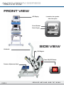
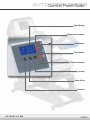
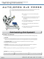
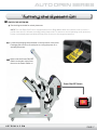
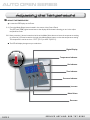
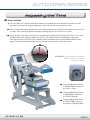
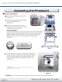
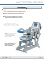
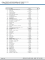
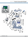
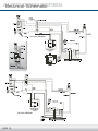
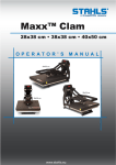
AUTO OPEN SERIES
6x6 PRESS
O P E R A T O R’ S M A N U A L
Safety Instructions
When using your heat press,
basic precautions should always be followed,
including the following:
1. Read all instructions.
2. Use heat press only for its intended use.
3. To reduce the risk of electric shock, do not immerse the heat press in water or other liquids.
4. Never pull cord to disconnect from outlet, instead grasp plug and pull to disconnect.
5. Do not allow cord to touch hot surfaces, allow heat press to cool completely before storing.
6. Do not operate heat press with a damaged cord or if the equipment has been dropped or damaged.
To reduce the risk of electric shock, do not disassemble or attempt to repair the heat press. Take it
to a qualified service person for examination and repair. Incorrect assembly or repair could increase
the risk of fire, electric shock, or injury to persons when the equipment is used.
7. This appliance is not intended for use by persons (including children) with reduced physical, sensory
or mental capabilities, or lack of experience and knowledge, unless they have been given supervision
or instruction concerning use of the appliance by a person responsible for their safety.
8. Close supervision is necessary for any heat press being used by or near children. Do not leave
equipment unattended while connected.
9. Burns can occur when touching hot metal parts.
10. To reduce the likelihood of circuit overload, do not operate other high voltage equipment on the same
circuit.
11. If an extension cord is necessary, then a 20 amperage rated cord should be used. Cords rated for
less amperage may overheat. Care should be taken to arrange the cord so that it cannot be pulled
or tripped over.
Product Warranty Registration
Log onto www.Hotronix.com/registration
You must provide the Hotronix® heat press
serial number and model information.
SERVICE HOTLINE: 800.727.8520
AUTO OPEN
Table of SERIES
Contents
HOTRONIX.C OM
Machine View
4
Control Panel Guide
5
Operating Instructions
6-11
Connecting the System
Turning the System On
Adjusting the Temperature
Adjusting the Time
Adjusting the Pressure
Pressing
6
7
8
9
10
11
Replacement Parts List
12
Parts Location Guide
13
Electrical Schematic
14
Contact
15
AUTO
SERIES
MachineOPEN
View
FRONT VIEW
LED Display
Located on the opposite
side of the press
Circuit Breaker
Power Supply
SIDE VIEW
Lift Handle
12V Magnet
Power ON/OFF Switch
Pressure Adjustment Knob
ON
PAGE 4
OFF
SERVICE HOTLINE: 800.727.8520
AUTOControl
OPEN
SERIES
Panel
Guide
Digital Display
Temperature Indicator
Set Indicator
Time Indicator
Pressure Indicator
Increase
Mode Select
Decrease
HOTRONIX.C OM
PAGE 5
AUTO
OPEN
SERIES
Operating
Instructions
AUTO
OPEN
6x6
PRESS
The Auto Open 6x6 Press Operating Instructions are designed with the user in mind.
Carefully read and follow the step-by-step instructions for best results.
To avoid burns, do not touch the heated platen
during use.
Keep hands clear of the upper platen of the press
during platen lock down as the pressure may
cause injury.
Press should be placed on a sturdy, suitable stand
at least 36”L x 24”W x 29”H.
Work area must be kept clean, tidy and free of
obstructions.
Power supply cord must be disconnected before
cleaning or servicing press.
Connecting the System
1. CONNECT THE POWER CORD
1.1 Connect the power cord into a properly grounded electrical outlet with a sufficient amperage rating.
VOLTAGE
120 Volt - The Auto Open 6x6 Press requires a full 10 amp grounded circuit for 120 volt operation.
220 Volt - The Auto Open 6x6 Press requires a full 10 amp grounded circuit for 220 volt operation.
EXTENSION CORDS If used, should be as short as possible and not less than 12 gauge.
Heavy duty cords are recommended.
CIRCUITS that have less than 10 amps or that have other high demand equipment or appliances
(especially more than one heat seal machine) plugged in, should not be used.
NOTE: If the supply cord is damaged, it must be replaced by the manufacturer, its service agent or a
similarly qualified person in order to avoid hazard. Use SJT type, rated 300 V for replacement.
CAUTION Failure to follow these instructions will cause:
1. Erratic controller functions.
PAGE 6
2. Inaccurate displays and slow heat-up.
3. The circuit breaker to disengage.
SERVICE HOTLINE: 800.727.8520
AUTO OPEN SERIES
Turning the System On
2. SWITCH THE SYSTEM ON
See the diagram below for switch placement.
NOTE: The Auto Open 6x6 Press is equipped with an Auto Sleep Mode. When the machine is not in use for a
period of two hours, it will enter an energy saving sleep mode. To restore to normal operating mode, press any
button on the display panel and allow the heat press to return to the target temperature
Locate the packaging bolt positioned on the top-center of the press.
Packaging bolt must be removed prior to turning the press on or
operating the press.
Now, locate the Power ON/OFF
Switch on the side of the press,
then turn the Power Switch on.
Power ON/OFF Switch
ON
HOTRONIX.C OM
OFF
PAGE 7
AUTO OPEN SERIES
Adjusting the Temperature
3. ADJUST THE TEMPERATURE
Locate the LED Display on the Press.
3.1 Press the Mode Select button located in the center of the Control Panel.
The (SET) and (TEMP) lights located next to the display will illuminate indicating you are in the adjust
temperature mode.
3.2 Next, press the (-) button located to the left of the Mode Select button to lower the temperature setting,
or press the (+) button located to the right of the Mode Select button to raise the temperature setting.
The temperature can be set from 176° F (79° C) to 430° F (220° C).
The LED will display changes as you make them.
Digital Display
Temperature Indicator
Set Indicator
Time Indicator
Pressure Indicator
Increase
Mode Select
Decrease
PAGE 8
SERVICE HOTLINE: 800.727.8520
AUTO OPEN SERIES
Adjusting the Time
4. ADJUST THE TIME
Your Auto Open, 6 x 6 Press has two time settings. This will allow you to set different times when a two hit
application is required. For single hit applications, you simply set both time settings the same.
Once you have adjusted the temperature, press the Mode Select button again. This will advance you to the Time
#1 mode. The set and time lights will illuminate, indicating that you are in the Time # 1 mode.
Adjust the time in the same manner that you adjusted the temperature. Once you have the Time # 1 set, push
the Mode Select button again to advance to the Time # 2 setting. All three red LED lights will illuminate
indicating that you are in the Set Time # 2 Mode. Select the desired time and push the Mode Select button
again to exit the time settings. All lights will be off and the press will return to the print mode.
REMEMBER: Press the Mode Select button
ONCE to advance to the Adjust
Temperature Mode
Press the Mode Select button
A SECOND TIME to advance to
the Time #1 mode.
Press the Mode Select button
A THIRD TIME to advance to
the Time #2 Settings.
Press the Mode Select button
A FOURTH TIME to return to
the Heat Up/Operating Mode.
HOTRONIX.C OM
PAGE 9
AUTO OPEN SERIES
Adjusting the Pressure
5. ADJUST THE PRESSURE
First, locate the LED Display on the Press.
(See figure 1)
The Pressure Adjustment Knob is located in
the center of the heat platen
(See figure 2)
Adjust the pressure by turning the knob
clockwise to increase pressure and counter
clockwise to decrease pressure.
PRESSURE READOUT
A visual Pressure Readout is located on the lower right side of the LED Display.
When the handle is locked into the Print Position, a pressure number will be
displayed. Readout will be on a scale of 0 - 9. A 0 Pressure readout would
indicate no pressure at all and 9 would indicate very heavy pressure.
(See figure 1)
1 - 3 = Light Pressure
4 - 7 = Medium Pressure
8 - 9 = Heavy Pressure
Figure 1
To adjust the Pressure, simply turn the Pressure Adjustment
Knob to the right or clockwise to increase the Pressure and to
the left or counter clockwise to decrease the Pressure. The
readout will display the Pressure when locked down in the
print position.
REMEMBER: To allow for the thickness of your garment
when adjusting the pressure.
Pressure Adjustment Knob
Figure 2
WARNING: Structural damage caused by excessive pressure is not covered under the limited warranty!
PAGE 10
SERVICE HOTLINE: 800.727.8520
AUTO OPEN SERIES
Pressing
6. PRESS
Once your equipment has reached the designated temperature:
Position the garment and application and proceed to press.
Lower and lock the heat platen into the press position.
This procedure will start the automatic timing process.
The timer will automatically count
down and lift the heat platen into the “UP”
position when the press cycle is complete.
NOTE: Please be aware after time
is complete, gas shocks will
automatically release the platen
into the “UP” position.
The time will automatically re-set
and you are ready to continue
with the next application.
HOTRONIX.C OM
PAGE 11
AUTO
OPEN
SERIES
Replacement
Parts
List
Item #
1
2
3
4
5
6
7
8
9
10
11
12
13
14
15
16
17
18
19
20
21
22
23
24
25
26
27
28
29
30
31
32
33
34
35
36
37
38
39
40
41
42
43
44
45
46
47
48
PAGE 12
Part Name
Hex Soc Button HD #10-32 x 1/2”
Rubber Foot
Acorn Hex Nut
Adjustment Spindle
Lower Platen 6 x 6
Silicone Pad Gray 6 x 6 Blue
Heat Platen 6 x 6
Heat Platen Cover 6 x 6
Finish Washer
Cover Screw 10-24x1/2”
Shoulder Bolt
Hex Soc HD Cap Screw 1/2” - 13 x 3/4”
All Thread Pin 1/4 - 20 x 4 3/4”
PVC Spacer 1/2” I.D. x 5”
Blue Foam Grip
JCN Nut
Electromagnet
Silicone Pad 5/16” I.D. x 1 3/4” O.D.
End Cap
Hex Soc HD Shoulder Screw 5/16” x 1/2”
6 x 6 Heater Arm
PVC Spacer 1/2” I.D. x 3.30”
Lift Links
Steel Pin 1/2” Dia. x 5 7/8”
Nylon Washer
Steel Spacer
Hub Cap 1/2”
Probe
Conduit 12”
Nylon Hex Nut
Gas Spring
Ball Stud 10mm
Phillips Pan HD Screw #6 - 32 x 1/2”
Steel Pin 1/2” Dia. x 6.45”
PVC Spacer 1/2” I.D. x 3.80”
PVC Spacer 1/2” I.D. x .7”
Base 6 x 6
Proximity Switch
Circuit Breaker
STX Housing
On/Off Switch
Display Overlay
Terminal Block
Triac
Controller Bracket
SSTT Control Board
Handle Assembly 6 x 6
Steel Pin 1/2” Dia. x 4.69”
Part #
Qty.
3-1011-164
1-1256
3-1011-182
1-1023
KIT 3-6911
1-2138
3-1334
2-1662
1-1063
3-1011-217
3-1011-121
3-1011-236
1-1042-1
1-2096
1-2115
2-1006-2
1-1945-1
1-2104
1-1999
3-1011-233
KIT 3-6912
1-1049-1
KIT 3-6909
2-1055-9
1-1048-3
1-2114
1-1107-1
1-1272-1
1-1048-2
2-1006-20
1-2246
1-1939
3-1011-152
2-1055-11
1-1049-5
1-1049-4
KIT 3-6907
1-1211
1-1456
4-1172
1-2087
1-2018-1
1-1290
1-1059
2-1661
1-2129
KIT 3-6910
2-1055-15
4
4
4
1
1
1
1
1
4
4
1
1
1
1
1
2
1
1
2
1
1
1
2
1
8
2
8
1
1
2
1
2
4
2
1
2
1
1
1
1
1
1
1
1
1
1
1
1
SERVICE HOTLINE: 800.727.8520
AUTO
OPEN
SERIES
Parts
Location
Guide
HOTRONIX.C OM
PAGE 13
AUTO
SERIES
ElectricalOPEN
Schematic
US 120 V VERSION
US 220 V VERSION
CE 230V VERSION
PAGE 14
Contact
Stahls’ Hotronix®
One Paisley Park
Carmichaels, PA 15320
U.S.A.
Technical Support
800 . 727 . 8520
Monday - Friday
8am - 7pm EST
Customer Service
800 . 727 . 8520
Monday - Friday
8am - 5pm EST
Replacement Parts
800 . 727 . 8520
8am - 7pm EST
Web
Hotronix.com
This document includes multiple trademarks and describes equipment covered by many patents
that are owned by GroupeSTAHL and/or its subsidiaries. GroupeSTAHL enforces its rights
to protect these intellectual properties. © 2013
Rev. A 9-12
Doc. STX6 9-12
Proudly made in the U.S.A.
One Paisley Park . Carmichaels, PA 15320, U.S.A.
Tech Support - Customer Service - Replacement Parts: 800 . 727 . 8520
Web: Hotronix.com