1
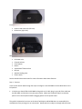
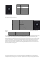
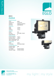
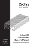
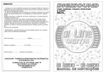
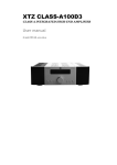
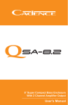
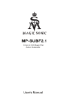
zoet dS Series Setup Guide The zoet dS AMP Series consists of both IP based amplifiers and IP based digital to analog converters (DACs). This Quick Setup Guide is intended to help facilitate a quick and easy way to setup your dS AMP Series product for zöet with Ethernet connectivity, or playGo with Wireless connectivity. For the purpose of this Guide, instructions are provided for the dS2 AMP versions. However as long as the dS2 DAC is connected to a powered amplifier or powered speakers the same instructions can be followed. What’s in the box: dS1 AMP or dS2 AMP IP based amplifier IEC power cord Ethernet Cable This document Specifications: Mono or Stereo Output power into 4Ω Output power into 8Ω Frequency response THD Power requirements Typical power usage Rack mountable Dimensions Shipping weight dS1 AMP1-250 Mono 1x210W 1x120W 20Hz – 20kHz +0.3/-0.5dB dS2 AMP1-90 Stereo 2x90W 2x50W 20Hz – 25kHz +/- 0.5dB dS2 AMP1-125 Stereo 2x125W 2x65W 20Hz – 20kHz +/-0.15dB ~0.0055% 120 VAC 3.15A 60Hz/ 250 VAC 2.5A 50Hz <10W Yes 3” X 8” X 8.5” Approximately 7 lbs <0.05% up to 75Wrms 120 VAC 5.15A 60Hz/ 250 VAC 4.15A 50Hz <8W Yes 3” X 8” X 8.5” Approximately 5 lbs ~0.003% 120 VAC 5.15A 60Hz/ 250 VAC 4.15A 50Hz <10W Yes 3” X 8” X 8.5” Approximately 5 lbs What you need before you get started: To use the dS AMP with zoet you will need a zoet dB1 with an Ethernet-based network. OR To use the dS AMP Series products wirelessly with playGo you will need a playGo USB tx (transmitter). Passive speakers (Powered Speakers or Power Amplifier for dS2 DAC) Speaker cables (RCA Cables for dS2 DAC) AC inlet for power About the dS AMP Series This guide is believed to be correct at the time of publication and BICOM takes no responsibility for consequences from printing error or inaccuracies. Specifications are subject to change without notice. Front Power mode status LED (left hole) IR Receiver (right hole) Back IEC Power Inlet Channel Selector Zone Selector Button 10/100 BaseT Ethernet Port IR Input Speaker binding posts Power switch See the Detailed Overview section for more information about these features. Step 1 – Connect In this section we will walk through the steps to configure a zoet dS2 AMP1 into the Main Room in the left position. 1. In the box you should find the dS2 AMP1 along with an AC cable, plug in one end of the cable into the dS2 AMP1 and the other into your power outlet. Make sure the On/Off switch on the back panel is still in the off position before plugging power into the power outlet. This guide is believed to be correct at the time of publication and BICOM takes no responsibility for consequences from printing error or inaccuracies. Specifications are subject to change without notice. 2. Now let’s connect your dS1 to the dB1. Click one side of the network cable into your dS2 AMP1 and the other into the dB1’s Ethernet jacks, any one of those jacks will work. You may also connect the dS2 AMP1 to the dB1 by ensuring both are connected to the Ethernet Network. 3. Connect speakers using speaker cable to the audio output jacks, it is recommended that the speaker cables are terminated with banana plugs. Tighten the binding posts to ensure a good electrical connection. Step 2 – Configure We’re almost there, let’s check everything now before we power on the system. 1. Make sure the dS2 AMP1 zone is properly selected. Since this is the first room, make sure that the dS2 AMP1 Zone Switch is pointing to Main Room. 2. Make sure the zöet speaker’s positions are properly selected – set to position A. (The dS2 AMP1 products support up to two channels and have several configurations available. Please refer to the Channel Settings for more information. For the purpose of this Guide we will configure the channels as Front Left & Front Right, which is position A.) Proceed to Step 3A for connecting to the zöet dB1. Proceed to Step 3B for connecting to the playGo USB tx. Step 3A – Power On with zoet 1. Flip the dB1 back panel on/off switch to the on position, it will then light up and power on. 2. Now flip the dS2 AMP1 power switches to the on position. 3. The dB1 and dS2 AMP1 are ready to use together, select an input and begin enjoying high quality IP based audio. Step 3B – Power On with playGo 1. Conenct the playGo USB tx to your PC or Mac and ensure that it is powered on, if no other playGo devices or zöet wireless products are powered on the playGo USB tx should light up red. 2. Now flip the dS2 AMP1 power switches to the on position. 3. Once the dS2 AMP1 is powered on press the Button on the back panel, you may need a pencil to easily depress the Button. At this point the SYS LED should cycle between Green, yellow, red, and off states – this shows you that the dS2 AMP is in pairing mode. Now press the Connect button underneath the playGo USB tx, which should start cycling colors as well. If speakers are properly connected the dS2 AMP will create a chime sound confirming that pairing is complete. In any case it will take the playGo USB tx 30 seconds before exiting pairing mode. This guide is believed to be correct at the time of publication and BICOM takes no responsibility for consequences from printing error or inaccuracies. Specifications are subject to change without notice. 4. Now you are ready to enjoy high quality wireless audio. Detailed Overview The dS AMP Series are sleek IP-based amplifiers. This section provides detailed information about the innovative features that may not be evident upon first inspection. Power mode status The front panel of the dS AMP Series consists of two small openings; the one on the left indicates the power mode status. There are two power modes: idle and active. Idle mode is indicated by a RED color, the dS AMP Series enters this mode when audio is not being output and as such it enters a lower power usage mode even though it is still fully communicating with zöet or playGo. The active mode is indicated by a WHITE color, the dS AMP series enters this mode when it is actively engaged and this usually indicates that audio is being output. Front Panel IR Receiver There is another small opening on the front of all dS AMP Series amplifiers; this opening on the right is the IR receiver to be used with zoet remote controls. For the IR receiver to be active the dS AMP Series must be in use within a zoet network and must be set to a zone other than the Main Room. The IR Receiver is disabled in the Main Room because the dB1 handles IR commands for the Main Room. The front panel IR Receiver is also disabled when the rear panel IR receiver has an external IR receiver connected to it. When connected to speakers the dS AMP Series will provide an audible click when IR commands are being received. IEC power inlet The dS AMP Series are factory configured for either 120V or 220V usage. Please check the packaging before connecting your dS AMP Series to the power outlet. CAUTION! Never make or break connections to the dS AMP Series Power Amplifiers unless it and all associated components are powered off. Channel selector The dS AMP Series consists of both mono (dS1) and stereo (dS2) configurations. These two different versions have two different usages for the Channel selector. dS1 AMP Channel selector: This guide is believed to be correct at the time of publication and BICOM takes no responsibility for consequences from printing error or inaccuracies. Specifications are subject to change without notice. Position A B C D E F G H Definition Center Right Right surround Right back Reserved Left back Left surround Left dS2 AMP or DAC Channel selector: Position A B C D E F G H *B & H setups: Definition Left & Right Right & Right Surround* Dual Mono Downmix Center & Sub Dual Sub Left Back & Right Back Left Surround & Right Surround Left & Left Surround* positions have alternate Alternate Position B H Definition Right Surround and Right Back Left Surround and Left Back To enter/exit the alternate mode, power on the dS2 with Ethernet disconnected and the position rotary in the A position. After seeing the occasional quick GREEN blinks, press and hold the factory reset button and before the sweep tone starts within a few seconds, turn the position rotary to B (for Rs+Rb) or H (for Ls+Lb) position. The Sys LED will rapidly blink green and a bell sound will be heard from the speakers connected to the dS2 confirming the setup. The dS2 will then reboot to activate the new position. During boot, the Sys LED will blink alternating RED-GREEN a few times to let the user know alternate positions are being used. This guide is believed to be correct at the time of publication and BICOM takes no responsibility for consequences from printing error or inaccuracies. Specifications are subject to change without notice.