1
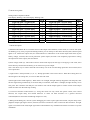
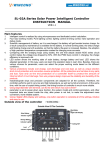
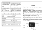
SLZ30 solar regulator user manual
Solar controller for PV systems, coordination of solar panels, batteries and work load, is a very important
photovoltaic system component. It makes the whole solar system work efficiently and safely.
Solar street light controller is mainly used for domestic, commercial, factory, transport, pastoral areas,
communication and other photovoltaic power systems.
Ⅰ.Key Features:
1. Using a single chip and special software achieve the intelligent control.
2. Using battery discharge rate characteristics modify the discharge control. Final discharge voltage is the control
point modified by discharge curve to eliminate the inaccuracies by a simple over discharge voltage. In accord with
inherent characteristics of the battery, different discharge rates has the different final discharge voltage to ensure
the battery to be used effectively.
3. Over charge, over discharge, short circuit, overload protection, reverse polarity protection, reverse current
protection at night, automatic control and so on; more protection from damaging any parts and burning insurance
out.
4. Adopting series connected type PWM as the main circuit, the voltage loss of the charge loop lower nearly half
compared with the circuit using the diode's charge reduced; in contrast to non-PWM, the charge efficiency is
higher 3% - 16%; an increase of power utilization time; normal direct charging; automatically control of float
charging make sure the system with long lifespan.
5. Accurate temperature compensation.
6. Intuitive LED indicates the current battery status to make sure that users understand the behavior in service.
7. Cancel set point adjustment and control of potentiometer, and use of Flash memory to record the work control
points to set the digitization to eliminate the vibration due to deviation and reduce errors and reliable factors by
drift and other control points.
8. Using of soft-touch keys is convenient and aesthetic.
Ⅱ.Interface descriptions:
SC: (solar charging indicator);
Off: disconnected solar cells or without enough sun, charge off;
Lighted: sunny and not over charge the battery, charging in progress;
Flashing: sunny, but the battery has sufficient, charge off.
BS: (battery status indicator);
Red flickering: low voltage protection of battery starts, turn off the load output;
Red lighted: battery power is low, to maintain the load output state;
Orange lighted: battery power is in the middle, allowing starting load output;
Green lighted: battery is fully charged to maintain the load output state;
Green flickering: the battery is fully charged; to maintain the load to the output, will close the charging circuit.
LS: (load status indicator);
Off: load off;
Lighted: load starts;
Slow flashing: load current is too large, such as continuous over-current, getting to the state of protection after a
presupposed time;
Fast flashing: load short-circuit or over current time out, system protection has been launched after a certain time,
automatically attempt to restart the load, if such overload fault has been ruled out, then enter into the normal
working condition.
CTRL: auxiliary control output;
TC: temperature compensation probe input;
S+/S-: solar cells connection;
B+/B-: battery connection;
L+/L-: load connection;
DS1: mode display;
S1: control / setup button;
Ⅲ.State instructions
1. Controller solidly fixed.
2. Wire preparation: It is recommended to use multi-strand insulated copper wire. Firstly, make sure the length of
the cord, secondly, ensure the installation location in the circumstances, thirdly, try to minimize the connection
length to reduce power consumption. According to not more than 4A/mm2 in accordance with the current density
of selected cross-sectional area of copper wire, the controller side of the first strip 5mm of insulation should be
shucked off.
3. Firstly, connect battery termination to the controller, and then connect to the other ends of the battery. Pay
attention to +, -, do not be reverse. If the connection is correct, BS should be lighted, according to buttons to check.
Otherwise, need to check the connection. In case of reverse, will not burn any part of the insurance and damage
any part of controller, fuse only as the end protection of a controller itself to protect the amount of internal short
circuit damage.
4. Photovoltaic cells’ wires connected, connect solar panels termination to the controller, and then the other ends
connected to solar panels. Pay attention to +, -, do not be reverse. If it is a sunny day, charging indicator light
should be bright. Otherwise, there is need to check the connection.
5. Load connected: connect the wire of load to the controller output, pay attention to +, -, do not be reverse.
Otherwise, it would burn appliances out.
6. Connecting photovoltaic cells and the load wires as followings: remain a curvature along the wire to prevent the
controller from rain water.
Ⅳ.Mode setting table:
Setting Table of Operation Mode
LED display Working code LED display Working code
Mode
Light-off open + Light-off off
Light-off open + 1 hour delay
Light-off open + 2 hour delay
Light-off open + 3 hour delay
Light-off open + 4 hour delay
Light-off open + 5 hour delay
Light-off open + 6 hour delay
Light-off open + 7 hour delay
Light-off open + 8 hour delay
LED
0
1
2
3
4
5
6
7
8
Mode
Light-off open + 9 hour delay
Light-off open + 10 hour delay
Light-off open + 11 hour delay
Light-off open + 12 hour delay
Light-off open + 13 hour delay
Light-off open + 14 hour delay
Light-off open + 15 hour delay
Universal Charger mode
Debug mode
LED
9
0·
1·
2·
3·
4·
5·
6·
7·
Ⅴ.Mode description:
a) Manual mode-Hand(H):For manual control of the output load conditions, in this mode, in a non-set state (DS1
not blinking) every time you press the Settings button, you can startup or shut down the load, (DS1) decimal point
lights or set off that the output state, the load indicator LS indications of the actual output load status (by the
battery voltage, overload, short circuit protection system impact, the load is not completely equivalent to setting
the output state of the output), the same below.
b) Pure charger mode (0): This mode will turn off the load output, but the logic of charging is still valid; if the
load is directly connected to the battery, it can still receive power output.
Note: The direct way to connect the load to the battery can not be over-discharge protection and overload, short
circuit protection.
c) Light-control + delayed mode (1-9, 0. -3.): Startup procedure is the same as above. When the working hours of
the load gets to the setting time, it is time to shut down the load.
d) Pure light-control mode-Light (L): When there is no sunlight, the light intensity dropped to start the point, after
the start signal being confirmed by 10 seconds delay of controller; when there is sunlight, the light intensity rise to
start point. The controller will delay for one minute to turn off the output signal to confirm closure of the output
and at the same time the load stop working.
e) Universal controller mode-Current (C): Using this mode can only cancel the optical control, time control
function, the output delay and related functions to retain all other functions as a general universal
controller(buttons control the load through output on or off).
f) Debug mode-Debug (D): used for system debugging, the same as pure light control mode, only the delay of the
judgment output light signal control (1min/10s) has been canceled in order to retain all other functions. No light
signal is connected to the load, bright signal that is off-loaded for easy installation check the correctness of system
installation.
Ⅵ: Technical specification
Table of Product Parameter
Model: SLZ30-6A, SLZ30-10A, SLZ30-20A, SLZ30-30,A ; Fixed charging current: 6A, 10A, 20A, 30A
Rated load
electric current 10A 20A 30A
System Voltage 12V, 24V, 36V, 48V
Over-load protection >1.25 multiple Nominal current,30 seconds or >1.5 Multiple Nominal current,1 seconds, and
>2.5 Multiple Nominal current, Over-load protection movement
No-load loss <6mA
Charging circuit
voltage drop ≤0.26V
Load circuit voltage
drop ≤0.15V
Over voltage
Protection 17V /12V; 34V /24V
Work temperature Technical grade:-35℃to +55℃
Boost charge voltage 14.8V; x2/24V(keep 10-min) (Only applied when over discharge appears)
Direct charge voltage 14.4V; x2/24V(keep 10-min)
Float charge voltage 13.6V; x2/24V(keep working until drop to the point of charge return voltage action)
Charge return
Voltage 13.2V;×2/24V;
Temperature
compensation
-5mV/℃/2V
Lower voltage indicate 11.2V; x2/24V
Over discharge voltage 10.6V no load-real-time modified voltage by the discharge rate; X2/24V
Over discharge return
Voltage: 11.8V; 2/24V
Control mode The way of PWM Pulse-duration modulation
Attention:If product instruction has the modification, Please contact us to know more.