1
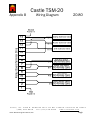
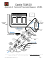
CASTLE, INC
MORTISE MACHINE
MODEL TSM-20
OPERATOR’S MANUAL
Addendum
Revised: December 16, 2010 (rev 2)
CASTLE, INC.
MORTISE MACHINE MODEL TSM-20
OPERATOR'S MANUAL
ADDENDUM
TABLE OF CONTENTS
Page #
1.0
SAFETY SWITCH CHECK ........................................................................................................... 1
2.0
AIR PRESSURE REGULATOR………………………………………………………………….2
3.0
SOLENOID MANIFOLD - CLEANING....................................................................................... 3
4.0
DRIVE CYLINDER SQE CLEANING.......................................................................................... 4
50
TSM-20 PARTS LIST..................................................................................................................... 5
Appendix A - Wiring Diagram..................................................................................................................... 6
Appendix B - Carriage Switch Diagram ..................................................................................................... 7
Appendix C - Solenoid Pneumatic Diagram ............................................................................................... 8
TSM-20 Operator’s Manual
Page ii
CAUTION: ALWAYS DISCONNECT POWER AND AIR BEFORE ATTEMPTING ANY
MAINTENANCE OR TESTING ON YOUR CASTLE MACHINE!
1.0
SAFETY SWITCH CHECK
The safety switch on the TSM-20 is a micro switch located on the outside of the control box (Fig 1).
When the safety buttons at the rear of the worktop are depressed by the stock, they actuate a blade inside
the machine that presses against the button of the micro switch. Combined with the micro switch in the
foot pedal these two micro switches are responsible for initiating the cycle on the TSM-20. If the switch
has failed then the machine will not begin the cycle, essentially your clamp will not go down and the
routers will not move, though they will turn on.
FIG 1
1.1
To Test:
Disconnect air and power.
Test for continuity at the switch by connecting the ohmmeter leads to wired side of the micro
switch. You will need to remove the orange cover plate to do this.
3. Press in the button on the micro switch. If the switch is working you should register continuity
after you press in the button.
4. If no continuity is registered then the switch needs to be replaced.
1.
2.
TSM-20 Operator’s Manual - Addendum
1
CAUTION: ALWAYS DISCONNECT POWER AND AIR BEFORE ATTEMPTING ANY
MAINTENANCE OR TESTING ON YOUR CASTLE MACHINE!
2.0
INTERNAL AIR PRESSURE REGULATOR
The internal air pressure determines the drill feed rate and the overall speed of the machine. The factory
setting is 75 PSI. It is important for the machine function to have at 75 PSI to the machine.
Locate the regulator in the control box (Fig 2). Unlock the yellow lock ring by pulling it slightly toward
the black knob. Turn the knob to the right (clockwise) to increase pressure. Turn the knob to the left
(counter-clockwise) to decrease pressure. Push the lock ring back in when done.
To completely reset the pressure, turn the knob all the way counter-clockwise and then turn it 5-6
full turns clockwise. This should bring your pressure to approximately 75 PSI.
NOTE: The speed of the cycle stroke is directly proportional to the pressure to the machine.
Cycling too slow may cause drill bits to heat up in the wood and may cause separation. Cycling
your machine too fast may cause undue pressure to the drill bits and may cause breakage and/or
over-sized holes.
PRESSURE
REGULATOR
FIG 2
TSM-20 Operator’s Manual - Addendum
2
CAUTION: ALWAYS DISCONNECT POWER AND AIR BEFORE ATTEMPTING ANY
MAINTENANCE OR TESTING ON YOUR CASTLE MACHINE!
3.0
SOLENOID MANIFOLD CLEANING
Begin by removing the control box from the machine. This can be done by removing the four screws on
the outside of the case and sliding the box out. Once out, remove the plate from the front of the control
box.
The coil located closest to the regulator in the upper left side of the control box (Fig 3) operates the
Clamp. The middle coil actuates the Drill cycle and the coil furthest from the regulator actuates the
Router.
TOOLS:
Pliers
Cloth or foam wrap to
cushion the pliers to
prevent damage to the coil
when removing.
3. Rubbing alcohol
4. Clean rag
5. Compressed air
1.
2.
SOLUTION STEPS:
1.
2.
3.
4.
5.
6.
7.
Use the pliers to remove the
nut from the top of the coil.
GENTLY remove the coil
housing.
Cushion the pliers and
CAREFULLY remove the
stem. Once you have
removed the stem verify
that the plunger actuates on
the bottom.
FIG 3
Blow out the manifold with air and wipe away any debris.
Wipe down the stem with rubbing alcohol.
Make sure that all parts of the manifold and the stem are clean.
CAREFULLY replace the stem using the cushioned pliers.
Replace the coil and nut.
TSM-20 Operator’s Manual - Addendum
CLAMP
DRILL
ROUTER
3
CAUTION: ALWAYS DISCONNECT POWER AND AIR BEFORE ATTEMPTING ANY
MAINTENANCE OR TESTING ON YOUR CASTLE MACHINE!
4.0
DRIVE CYLINDER SQE CLEANING
The drill solenoid is an air switch that controls the flow of air to the drive cylinder. The drive cylinder, in
turn provides the pressure to move the drill carriage through its cycle. If the air line becomes clogged the
drive cylinder may not have enough pressure to cycle the drill completely.
SOLUTION STEPS:
1.
2.
3.
4.
5.
6.
7.
8.
Open the back door
Inspect the hoses coming FROM THE DRIVE CYLINDER for holes and/or pinches.
Unplug the two DRIVE CYLINDER hoses from the solenoids. This is done by following the air
lines back to their connection at the control panel. The hoses should remain attached to the air
cylinder at the SQE’s (Fig. 4)
Dry cycle the machine:
a. Unplug the router motors
b. Hold in the safety stock sensors below the clamp with two scraps of wood. Be careful to
leave room for the router to come up through the work surface unobstructed!
c. Reach into the rear door opening and firmly grasp the yellow carriage.
d. Steadily pull and push the carriage fully back and forth to force air through the hoses. BE
SURE TO ALLOW THE AIR PRESSURE TO FULLY EXHAUSE OUT THE HOSES.
Make sure air is coming out of the
solenoids while dry cycling
The hoses attached to the cylinder
should exhaust air as you dry cycle
knocking loose any blockage out of the
brass SQE’s as well as cleaning any
debris out of the air hoses.
Press the hoses firmly back into the
push-in fittings.
Plug in the router motors.
FIG 4
TSM-20 Operator’s Manual - Addendum
4
TSM-20 PARTS LIST
Castle Part #
Part Description
Drill & Router Motors & Accessories
Porter Cable 3102 Trimmer Motor (Drills hole) DISCONTINUED
E23102
E26902
Porter Cable 6902 Router Motor (Routs pocket; mount with F14232 bolt) (same router as TSM-21)
D50014
1/4" Collet Assembly (for E23102 motor)
Note: Brass bushing no longer available; replaced by 1/4" shank on the bit
D50031
Collet Nut
Microswitches
E60286
Snap-action Microswitch (Silver push button) (Drill Stop, Rout Stop, and Wood Sensor Switch)
Note: Grainger Part No. 6X286 Manufacturer Part No. Z-15GQ-B7-K
E60284
Snap-action Microswitch (with Lever) (Used in older versions)
Note: Grainger Part No. 6X284 Manufacturer Part No. Z-15GW-B7-K
E07033
Microswitch (Small, white with Lever) (Used in oldest versions)
Note: Grainger Part No. 6A884 Manufacturer Part No. TMCG40
E07041
Control Board
E20120
Snap-action MicroSwitch (Small push button) (Foot Switch for TSM 20, 21 & 35)
Note: Grainger Part No. 6X283
EL-06 3-Relay Control Board (EL-06 is compatible with all models)
Note: Revision EL-05A and EL05B no longer available - Refer to Electrical Wiring diagram
DISCONTINUED
14 Pin Terminal Strip
E20014
14 Pin Terminal Strip (for Relay Control Board)
Regulator
P53000
Monnier Regulator
Note: Must be calibrated to 85psi by shipping dept. prior to shipping
Drive Cylinder
C21004
Drive Cylinder
Note: Same as TSM-21 drive cylinder
Manifold-Fabco
P13013
Fabco Valve Assembly (3 valves included with Manifold)
Solenoid Coil - Fabco
E20126
Solenoid Valve (Clamp, Rout and Drill valves)
Flow Control
P00117
SMC Flow Control
Note: Same as Feed Speed valve used on TSM-21 & 35
On/Off Toggle Switch
E75762
On/Off Switch (silver metal)
SQE (Super Quick Exhaust)
P10320
SQE 10-32 Clippard
Note: small, brass;
SQE (Super Quick Exhaust)
P10001
Humphrey SQE-1
Note: larger than P10320, octagonal, nickel
SQE White Nylon Barb
P10325
10-32 x 5/32 ID Black Barb (for P10320 when used as Clamp Exhaust)
P31032
10-32 x 10-32 White Nylon Coupling (for P10320 when used as Clamp Exhaust)
18 AWG Hook Up Wire
E18061
Brown
Castle TSM-20
Appendix B
Wiring Diagram
20.80
Castle, Inc. 1364 N. McDowell Blvd. PO Box 750236. Petaluma CA 94975
(800) 282-8338
Fax (707)765-0953
www.castleusa.com
Castle TSM-20 Diagnostic Manual, Rev.
Page
Castle TSM-20
Appendix B Carriage Switch Diagram 20.82
Castle, Inc. 1364 N. McDowell Blvd. PO Box 750236. Petaluma CA 94975
(800) 282-8338
Fax (707)765-0953
www.castleusa.com
Castle TSM-20 Diagnostic Manual, Rev. 2
Page
Castle TSM-20
Appendix C Solenoid Pneumatic Diagram 20.81
On / Off
Switch
14 13 12 11 10 9 8 7 6 5 4 3 2 1
E75762
Relay Board
Black line to
Router Feed Rate
Control
Nylon Barb
P18161
P16182
White Tubing
P16181
Router
Feed
Rate
Control
Black air line out to Router
end of Drive Cylinder
Router Feed
Rate Valve
P00117
Nylon Barb
P18161
P16182
Nylon Barb
P53000
Clear air line out to Drill
end of Drive Cylinder
Brass Check
Valve
P20020
M
Clamp
Solenoid
E20126
P53000
S
Air Pressure
Regulator
o
le
n
o
id
a
n
if
o
ld
Solenoid Manifold only
E20126
E20126
Nylon
Coupler
Black air line to
Clamp
Black Barb
P10325
P14170
Female Brass
Coupling
Brass Bushing
P10328
SQE, Super Quick
Exhaust Valve
Reducer Hex Nipple
E20126
Drill
Solenoid
P31032
Air In
Router
Solenoid
P20202
P10320
P14918
Castle, Inc. 1364 N. McDowell Blvd. PO Box 750236. Petaluma CA 94975
(800) 282-8338
Fax (707)765-0953
www.castleusa.com
Castle TSM-20 Diagnostic Manual, Rev. 2
Page


![2013 Gun List internet copy[2]](http://vs1.manualzilla.com/store/data/005851443_1-16b4e1bd3fc391c408d2005c48a2e336-150x150.png)