1
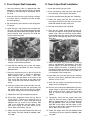
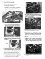
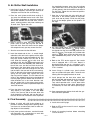
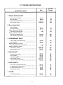
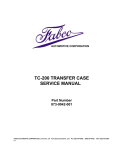
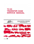
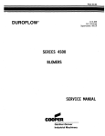
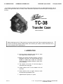
151 LAWRENCE DRIVE
TELEPHONE (925) 454-9500
LIVERMORE, CALIFORNIA 94551
FAX (925) 454-9501
Part numbers contained in this manual were in effect at the time the manual was approved for printing and are
subject to change without notice or liability, Fabco Automotive Corporation reserves the right to change parts at
any time.
AUTOMOTIVE CORPORATION
TC-38
Transfer Case
SERVICE MANUAL
Before ordering parts for a Fabco transfer case, please refer to the Fabco nameplate located on the
transfer case housing. Specify model number, serial number, part number, or other information that is
on the nameplate when ordering parts.
I. LUBRICATION
A. Initial oil change should be made after no more
than 5,000 miles have been driven.
B. Regular oil changes should be made at an interval
selected by the user. An interval between every
10,000 to 15,000 miles should be satisfactory
unless operating conditions indicate a lesser interval is necessary.
C. The location of the drain, fill and level plugs is
indicated on the next page.
D. Proper lubricant level is to the bottom of the oil
level hole.
E. Check lubricant level at regular intervals; watch
for indications of possible oil loss.
F. Approximate oil capacity is 7 quarts.
625 417
— 1—
Copyright © 1988 by FABCO AUTOMOTIVE CORPORATION
LIVERMORE, CA 94662
Recommended Lubricants
On Highway Vehicles
Type
Grade
Temperature
MIL-L-2104B
Heavy-Duty Engine Oil
SAE 50
SAE 30
Above + 10°F.
Below + 10°F.
Mineral
Gear Oil
SAE 90
SAE 80
Above + 10°F.
Below + 10°F.
MIL-L-2105B E.P.
Oil, except sulfur-chlorine-lead type.
SAE 90
SAE 80
Above + 10oF.
Below + 10°F.
Heavy-duty engine oil. Make sure to specify heavy-duty type meeting MIL-L-2104B specifications.
Mineral gear oil inhibited against corrosion, oxidation and foam.
Extreme pressure oils under some conditions might form carbon deposits on gears, shafts and bearings which
will result in transfer case malfunctions and premature failure. It is suggested that if these conditions exist, and
E.P. oil is being used, a change should be made to mineral gear oil or heavy-duty engine oil as recommended.
Off Highway & Mining Equipment
Type
Grade
Temperature
MIL-L-2104B
Heavy-Duty Engine Oil
SAE 50
SAE 30
Above + 10°F.
Below + 10°F.
Special Recommendation
For extreme cold weather where temperature is consistently below 0°F.
MIL-L-2104B
Heavy-Duty Engine Oil
SAE 20W
Below + 0°F.
1. Oil Level Plug
2. Oil Fill Plug
3. Oil Drain Plug
— 2—
Fig. 2
II. DISASSEMBLY
A. Preliminary Steps
1. After removing the transfer case from the vehicle, thoroughly clean the exterior.
2. Remove the drain plug and drain the unit.
Remove the cover.
3. Shift Components Removal.
a. Remove the indicator light switch, spacer
washers and, with a magnet, the plunger pin.
b. Cut lockwires from the fork retaining set
screws and remove the screws.
c. Remove the shift cylinder caps and tubes.
Remove the piston and shift shaft assemblies.
C. Intermediate Shaft Removal
1. Remove the front nut from the shaft.
2. Remove the rear bearing cap.
3. Engage the clutch gear into the underdrive gear.
Block between the clutch gear and the rear of
the case housing. Push the shaft and direct drive
gear out the back of the case. Catch the bearings and spacers as they come off the shaft.
D. Rear Output Shaft Removal
1. Push the shaft out the front of the case and out
of the gear, catching the bearings and spacers.
E. Front Output Shaft Removal
Follow procedure outlined under “B” (input shaft
removal).
F. Remove the bearing cups from their
gears only if replacing them.
As the shift forks are removed, tag each with
location and mark to indicate position and orientation thereby simplifying installation at
assembly.
4. Remove the nuts and take off all yokes or
flanges. The shafts can be prevented from rotating by engaging all three clutches.
5. Remove all seal carriers and bearing caps
except the rear intermediate cap and, if so
equipped, the PTO assembly.
6. Loosen all bearing locknuts.
B. Input Shaft Removal
1. Remove the spacer from the front of the shaft.
Pry the shaft forward, remove the bearing cup.
2. Remove the bearing locknut from the shaft.
3. Engage the clutch gear into the drive gear,
restrain the clutch gear (not the drive gear) while
pushing the shaft out the front of the case. Catch
the bearing cones and spacers as they come off
the shaft.
4. Do not remove the split ring from the shaft unless
it is being replaced.
Ill. TRANSFER CASE ASSEMBLY
A. General Precautions
7. Seals supplied by Fabco are coated on the outside and should not be coated with Permatex
before installation in their carriers. They should
be coated on the sealing lip with Lubriplate.
1. Read these instructions completely before starting reassembly. Refer to the appropriate
exploded view. Assemble, adjust and check in
the order shown.
8. Use Permatex Form-A-Gasket #2 or equal pliable
setting sealant on bolt threads. If bolt threads are
not sealed they will leak oil.
2. Parts must be clean. Gasket surfaces must be
free of old gasket material.
9. All bolts and nuts should be tightened to torque
indicated on torque chart.
10. Allow heated components to cool to room temperature before making bearing adjustments.
B. Clutch Gear and Bearing Assemblies
3. Select a work area that will maintain the cleanliness of the parts and the assembly. Mount the
case housing with the cover on top. The cover
side, the front and rear of the case should be
accessible. The housing must be restrained. A
sturdy work bench or special stand should be
used. The components of this transmission are
heavy and positioning and installing them will be
easier if the case is supported in the position
indicated.
4. Lubricate housing bores, shaft spline and bearing mounting surfaces, sealing lips on oil seals
with Lubriplate or equal. This is necessary to
reduce the chances of galling or scoring and to
provide initial lubrication for the oil seals.
5. Installation of gaskets, bearing carriers, seal carriers and caps will be simplified if two temporary
guide studs are utilized.
6. Universal joint yokes or companion flanges
should be coated with Lubriplate on the seal
operating area before installation. They should
be tightened into place with the locknuts tightened to the proper torque before the cover is
installed on the case and before the shim thickness is determined. Universal joint yoke or companion flange retaining nuts can be tightened or
loosened most easily when all components
except shift forks are in place. At that time it is
possible to engage both the direct drive and the
underdrive clutch gears and effectively lock all
the shafts against rotation.
— 4—
1. A light coat of Lubriplate should be applied to the
bore of the gear before pressing the cups into
place.
2. Check the end play as follows:
a. Match the gear with the shaft. Slip a clutch
onto the shaft (to aid in disassembling). Slide
a bearing cone onto the shaft followed by a
spacer. Put the gear into place and then the
second bearing cone. Clamp the bearingspacer-bearing assembly in place utilizing a
temporary spacer tube between the second
bearing cone and the nut.
b. The axial end play between the gear and the
shaft should now be between .003” and
.008”. If not, change the spacer between
bearing cones.
c. Remove the gear, bearing cones, spacers and
the clutch from each shaft. Keep the set of
parts thus selected in an area that will insure
their installation in the case as a matched set.
C. Front Output Shaft Assembly
1. Heat front bearing cone to approximately 250
degrees F. Use heat resistant gloves to handle
the bearing. Install bearing on the splined end of
the shaft.
2. Insert the shaft into the case passing it through
the clutch which is lowered into place through
the cover opening.
3. Slip one bearing cone onto the shaft along with
the spacer.
4. Lower the gear, with bearing cups installed, into
the case. Pull the shaft forward enough to allow
the shaft end to be inserted into the gear. Slip the
second bearing cone into place and slide the
spacer washer into place.
5. Install the rear bearing cone that has been
heated (as discussed in Step #1) onto the shaft.
Loosely install the bearing locknut.
6. Insert the rear bearing cup in place and temporarily install the cap without any shims using two
opposing bolts.
7. Install the front bearing cup in the case and the
gasket. Coat the seal — which has previously
been installed in the seal carrier — with Lubriplate. Also coat the splines on the end of the
shaft. Install the seal carrier on the front of the
case. Install bolts with threads coated with Permatex.
8. Coat the universal joint end yoke from the vehicle with Lubriplate on both the spline bore and
the sealing area. Install on the shaft and tighten
the locknut, taking care not to damage seal lips.
9. Remove the rear cap and tighten the locknut.
D. Rear Output Shaft Installation
1. Install split retaining ring on shaft.
2. Press front bearing cone into place tight against
shaft shoulder, install washer and locknut.
3. Coat the splined bore of the gear with Lubriplate.
4. Lower rear output gear into the case with flat
face against the back wall of the case, the chamfered side toward the front of the case.
5. Coat the shaft splines with Lubriplate.
6. Insert the rear output shaft through the front of
the case and align the shaft splines with the gear
splines. Use a brass or aluminum rod to protect
the threaded shaft end and tap the shaft into the
gear until the retaining ring seats in the chamfer
of the gear.
7. Install the spacer ring. Heat the rear bearing
cone to approximately 250 degrees. Use heat
resistant gloves to handle the bearing. Install
quickly, tapping into place, if necessary. Install
the spacer washer on the shaft. The shaft can be
moved toward the front of the case to allow visual inspection of the mating parts.
8. Install both front and rear bearing cups allowing
the rear cup to remain projecting from the case
between 3/8 and 1/4 inch.
9. Install the rear output carrier gasket and the rear
output carrier including seal.
10. Coat the seal surface and splined hole of the rear
output flange or yoke (from vehicle) with Lubriplate. Install on the shaft. Lightly coat the washer
face of locknut with Permatex; install and
tighten.
10. Once again, temporarily install the cap. Do not
install shims. Tighten the retaining bolt to
approximately 25 lb. ft. torque. Measure the gap
between the cap and the case housing. Add
.005” to this dimension and then select a shim
pack that is equal to this total within plus or
minus .003”. Install shims and cap.
11. Temporarily install the rear output shaft front
cover. Do not install shims. Tighten the mounting
bolts to approximately 25 lb. ft. torque. Measure
the gap between cover and the case housing.
Add .005” to this figure and then select a shim
pack that is equal to this calculated figure plus or
minus .003”. Install shim pack.
11. Check the shaft end float between the shaft and
the housing. End float should be between .003”
and .008”.
12. Check rear output shaft end float between shaft
and housing. End float should be between .003”
and .008”.
— 5—
E. Intermediate Shaft Installation
1. Drive the split ring onto the splined section of the
shaft from the chamfered end until it seats in its
groove. Slip the clutch onto the shaft from the
other end — with the external teeth away from
the split ring.
4. Pass the 34T direct drive gear (with the chamfered end of the bore toward the split ring)
through the rear opening and into place on the
shaft.
2. While the shaft is outside the case, slip one bearing cone into place. Add the spacer, the underdrive gear (with bearing cups), the second bearing cone, the spacer washer (on mechanically
driven speedometer models) and front bearing
cone which has been heated to 250 degrees F.
Handle the bearing with special heat resistant
gloves. On models with mechanically driven
speedometer, install the speedometer drive gear
spacer, the speedometer drive gear and locknut.
On models with electronic speedometer, install
washer and locknut.
5. Heat the intermediate shaft rear bearing cone to
250 degrees F; handle the heated part with heat
proof gloves. Place this part in place on the
shaft. Add the washer and the rear locknut.
6. Apply a light coating of Lubriplate to the bearing
cone bore in the intermediate shaft rear cup.
Press bearing cup into place.
7. Install a pair of guide pins in the case to guide
the cap into place. Hang the intermediate shaft
rear cap gasket on the guide pins. Position the
cap and tap it into place. Replace the guide pins
with capscrews.
8. Install the intermediate shaft front bearing cup.
9. Temporarily install the front cap tightening six
capscrews to approximately 25 lb. ft. torque.
Measure the gap between the cap and the case
housing. Add .005” to this dimension. Select a
shim pack equal to this total within plus or minus
.003”. Install the shim pack and front cap.
3. Lower this shaft subassembly into the case housing through the case cover opening. Point the
rear end of the shaft through the intermediate
cap opening. Now move the shaft forward and
out the intermediate shaft opening in the front of
the case housing.
10. Check the shaft axial float. End float should be
between .003” and .008”.
— 6—
F. Input Shaft Assembly
1. While the input shaft is not in the case:
a. Install the split retaining ring.
b. Slide the 19T underdrive pinion gear onto the
shaft. The counter bore in the gear should fit
completely over the split ring.
5. Put the input shaft rear bearing cup into place in
the case bore along with the spacer ring. NOTE:
This ring is not used when a PTO is installed.
Refer to PTO instructions.
c. Heat the input bearing cone to 250 degrees F,
handle with heat proof gloves and slip onto the
shaft tight against the gear.
6. Temporarily fasten the rear cap to the housing
with two opposing bolts without any shims.
7. Insert the input shaft front bearing cup in place.
Position the gasket on the front of the case.
Install the input seal carrier with seal to the front
of the case. Install the universal joint end yoke.
8. Remove the rear cap and install the rear bearing
locknut.
2. Position the direct drive gear, with bearing cups
pressed in, inside the case resting on the intermediate shaft’s direct drive gear and against the
housing wall.
9. Temporarily mount the cap with the capscrews
tightened to 25 lb. ft. torque. Measure the gap
between the cap and the case housing. Add
.005” to the measured dimension. Select a stack
of shims that is equal to the total plus or minus
.003”. Install the shims, cap and capscrews.
Fig. 15
3. While holding the clutch inside the case with the
external teeth toward the rear of the case, pass
the shaft subassembly through the front opening
and into the clutch. Slide a bearing cone into
place. Slide spacer onto the shaft. Lift the direct
drive gear enough to pass the shaft through.
4. Slip the second direct drive gear bearing cone
into the back of the gear. Heat the input shaft
rear bearing cone to 250 degrees F and slip into
place. Tap lightly to insure proper seating.
10. Check the shaft end float between the shaft and
the housing. End float should be between .003”
and .008”.
— 7—
G. Air Shifter Shaft Installation
the longitudinal groove away from the indicator
light switch hole. Push on the piston enough to
put the groove in the shaft under the set screw in
the shift fork. Tighten the set screw to specifications and lockwire.
1. Install two O-rings into the grooves on each of
the cylinder adaptors. Coat with gear lubricant or
Lubriplate and install on the case housing.
7. Soak the air shift piston felt strips with gear oil
and install in the shallow groove of the piston
(shift shaft side of piston). Install the shift piston
O-ring in the deeper groove on the pistons. Oil
the rings.
2. Place the small (piston-to-shift-shaft sealing) Oring over the threaded end of each shift shaft.
The shallow counterbore in the piston should be
toward the shoulder on the shift shaft; install a
piston, retaining washer and piston retaining nut
on each shaft. Tighten the nuts.
3. Install a spring on each shift shaft against the
piston. Place a nylon stop ring over the end of
each shift shaft. Insert the shafts into the proper
shift adaptor but only part way across the case.
8. The shift cylinder tubes are of differing lengths.
The shortest tube (which is
long) should
be slipped over the front axle shift piston on the
front of the case. The longest shift cylinder tube
(which is
long) should be fitted over the
high-underdrive shift piston on the rear of the
case.
4. Start the set screws into the shift forks.
5. Install the forked end of the 7 5/8" overall length
underdrive shift fork into the groove of the underdrive shift clutch (on the intermediate shaft). The
long hub section should face the rear of the
case. Slide the forward end of shift shaft into
underdrive shift fork. Put
overall length shift
fork (direct drive shift fork) long hub toward the
front of the case, into the case with the forks in
the groove in the direct drive clutch on the input
shaft. Now push shift shaft through this fork and
into the hole in the front wall of the case housing.
Push on the end of the piston and compress the
spring until the piston butts against the nylon
stop ring and the adaptor. This will allow the set
screw in the underdrive shift fork to be tightened
into the proper groove. Rotate both shift forks in
either direction but in the same direction and,
with the second fork in the proper place longitudinally, tighten set screws to specified torque and
install the lockwire.
9. Refer to the PTO service manual if the transfer
case is equipped with a PTO unit. Neutral is
obtained through the use of a “piggyback” cylinder mounted on the high-neutral cylinder when a
PTO is installed.
10. Insert O-rings in cylinder caps, install cylinder
caps on cylinder tube open ends. Fasten to case
housing with the appropriate bolts or studs.
11. Install plunger into the front drive switch hole
with the rounded end toward the shaft. Install the
shift indicator switch with one copper washer.
Test switch operation with a circuit tester while
shifting into and out of front drive. Add washers
as necessary to make the switch operate properly.
6. Place the forks of the front drive shift fork
long overall) in the groove in the front drive
clutch. Pass the rear end of the front drive shift
shaft through the shift fork and into the hole at
the back of the case. Rotate the shaft to position
12. Cover exposed end of shifter shafts with the gaskets and covers provided.
H. Final Assembly
3. Install drain and fill plugs.
1. Rotate all shafts with shift shafts shifted to all
positions. Observe through cover opening. Make
sure there are no loose tools, bolts or other foreign objects in the assembly.
2. Install cover gasket and cover, coat bolt threads
with Permatex, use a lockwasher on each bolt
and tighten to the specified torque.
4. Refer to PTO service manual if case is equipped
with a PTO unit.
5. Attach all mounting brackets before reinstalling
case in the truck.
— 8—
IV. TORQUE SPECIFICATIONS
Size
Location/Description
A. FRONT OUTPUT SHAFT
Front Seal Carrier Bolts
Rear Cap Bolts
Front Output Yoke Locknut
Rear Bearing Locknut
B. Rear Output Shaft
Front Cap Bolts
Rear Carrier Bolts
Models w/Mechanical Speedo
Front Bearing Retaining Nut
Models w/Electronic Speedo
Front Bearing Retaining Nut
Rear Yoke or flange Locknut
C. INTERMEDIATE SHAFT
Front or Mechanical Speedo Cap
Rear Cap Bolts
Models w/Mechanical Speedo
Front Bearing/Mechanical Speedo Nut
Models w/Electronic Speedo
Front Bearing Locknut
Rear Bearing Locknut
D. INPUT SHAFT
Front Seal Carrier Bolts
Rear Cap Bolts
PTO Mounting Bolts
Rear Bearing Locknut
Input Yoke Retaining Locknut
E. SHIFT SHAFTS
Seal Carrier & Cap Mounting Bolts
Air Cylinder Bolts, Studs or Nuts
Air Shift Piston Retainer Nut
Shift Fork Set Screws
F. COVER
Cover Mounting Bolt
REV 5/89
— 9—
Ft. Lbs.
Torque
FABCO MODEL TC-38
—FABCO AUTOMOTIVE CORPORATION—
TRANSFER CASE ASSEMBLY
SERVICE AND PARTS MANUAL
— 10 —
I. OPERATING INSTRUCTlONS
FABCO TC-38 TRANSFER CASE
A. Front Drive
When travelling through sand, loose dirt, mud,
snow, ice, or when ascending grades where the
rear wheels might spin, shift to front wheel drive for
better traction. Shift before the truck is in trouble.
Engagement and disengagement of the front drive
axle can best be made while the engine is pulling
lightly. It can be shifted at any speed provided the
rear wheels are not spinning. The transfer case is
equipped with a switch so that the shift is indicated
by a pilot light. The light will come on when front
drive is engaged.
B. Underdrive
When slow, positive pulling power is desired,
shift to underdrive. Underdrive may be used to obtain a convenient combination with third or direct
for climbing some grades. The transfer case should
be shifted between high and low range only when
the truck is stopped.
C. Power Take-Off
When the transfer case is equipped with a power
take-off, the PTO can be operated without moving
the vehicle. To engage, shift the automatic transmission into neutral and shift the PTO while the
engine is idling. After the PTO has been engaged,
shift the transmission to the desired gear. With a
manual transmission equipped vehicle, depress the
clutch pedal and shift into the desired transmission
gear, shift the PTO and release the clutch.
To disengage the PTO, shift the transmission into
neutral (manual and automatic), allow the machinery to come to rest, then disengage the PTO.
— 19 —