1
START OF OPERATION
Uppgjord/Prepared
Faktaansvarig - Subject responsible
SEA/TB/MP Stangelberger SEA/B/U
Dokansv/Godkänd - Doc respons/Approved
SEA/TB/MP
1(12)
Dokumentnr/Documentnr
1537-ASB 150 02 Uen
Kontr/Checked
Datum/Date
Rev
Tillhör/Referens-File/Reference
1999-08-10
G
ASB 150 02
Database reference
1537.fm
START OF OPERATION
ASB 150 02
UPDATE PAGES FOR CORDLESS
START OF OPERATION
Uppgjord/Prepared
Faktaansvarig - Subject responsible
2(12)
Dokumentnr/Documentnr
1537-ASB 150 02 Uen
Dokansv/Godkänd - Doc respons/Approved
Contents
Kontr/Checked
Page
1
General description . . . . . . . . . . . . 3
1.1
Supplementary documents. . . . . . . . 3
1.2
Fault locating. . . . . . . . . . . . . . . . . . . 3
2
Prerequisites . . . . . . . . . . . . . . . . . . 3
3
Preparations . . . . . . . . . . . . . . . . . . 4
3.1
Turn power on . . . . . . . . . . . . . . . . . . 4
3.2
WARM START . . . . . . . . . . . . . . . . . 4
3.3
COLD START . . . . . . . . . . . . . . . . . . 4
4
PROGRAMMING
THE SYSTEM. . . . . . . . . . . . . . . . . . 5
4.1
Trunk programming. . . . . . . . . . . . . . 5
4.2
Tie line programming . . . . . . . . . . . . 5
4.3
Programming the VMU HD
(hard disk). . . . . . . . . . . . . . . . . . . . . 5
4.4
Number series . . . . . . . . . . . . . . . . . 5
5
TEST PROCEDURES . . . . . . . . . . . 6
5.1
Extension lines . . . . . . . . . . . . . . . . . 6
5.2
Trunk lines. . . . . . . . . . . . . . . . . . . . . 6
5.3
VMU-boards . . . . . . . . . . . . . . . . . . . 8
5.4
CORDLESS . . . . . . . . . . . . . . . . . . . 9
5.5
CPU-D(_) . . . . . . . . . . . . . . . . . . . . 10
5.6
System clock. . . . . . . . . . . . . . . . . . 11
5.7
Handling/exchanging boards
while the system is in operation . . . 11
5.8
Upgrading or exchanging boards . . 11
5.9
CTI . . . . . . . . . . . . . . . . . . . . . . . . . 11
6
FINAL WORK. . . . . . . . . . . . . . . . . 12
Datum/Date
Rev
1999-08-10
G
Tillhör/Referens-File/Reference
START OF OPERATION
Uppgjord/Prepared
Faktaansvarig - Subject responsible
3(12)
Dokumentnr/Documentnr
1537-ASB 150 02 Uen
Dokansv/Godkänd - Doc respons/Approved
1
Kontr/Checked
General description
These instructions are intended for setting up the
ASB 150 02 system where the included units or the
entire system have/has been subjected to factory end
testing before delivery to the installation site.
Datum/Date
Rev
1999-08-10
G
2
extension lines
•
trunk lines
•
MDF for extension and trunk lines
•
programmed functions
•
information to the customer
The skilled technician should be familiar with the
PBX in terms of location of the switches on the
boards and the settings by RASC.
•
The system shall be mounted. Presently two
systems are available and connected in
accordance with:
INSTALLATION INSTRUCTION
1531-BDV 113 08 Uen for the BP 250 and
INSTALLATION INSTRUCTION,
1531-BDV BS 101 01 Uen for the BP 50.
•
A personal computer installed with the
maintenance program RASC (Remote Access
Supervision and Configuration, LZY 203 2250),
and Integrated Cordless System Manager
Software program (LZYNB 201 01) should be
available.
•
To connect the computer with the system, use
cord set TSR 902 0448/1 (PC and printer cable).
The instructions describe the test procedures that are
to be used.
The ASB 150 02 introduces with the release 9 the
functionality of exchanging boards of similar type and
exact configuration without the need of turning off the
mains power to restart the system. This functionality is
known under the term "hot swapping".
1.1
Supplementary documents
•
INSTALLATION INSTRUCTION,
(1531-BDV 113 08Uen
•
INSTALLATION INSTRUCTION,
1531-BDV BS 101 01Uen)
•
FAULT TRACING INFORMATION,
1545-ASB 150 02 Uen
•
RASC User Guide EN/LZT BS 102 023
1.2
Fault locating
If a fault is discovered, the directions given in FAULT
TRACING INFORMATION are to be followed.
Prerequisites
•
This document covers tests for the following:
•
Tillhör/Referens-File/Reference
START OF OPERATION
Uppgjord/Prepared
Faktaansvarig - Subject responsible
4(12)
Dokumentnr/Documentnr
1537-ASB 150 02 Uen
Dokansv/Godkänd - Doc respons/Approved
3
Kontr/Checked
Preparations
Datum/Date
Rev
1999-08-10
G
3.2
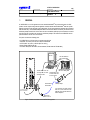
Remove the cabinet cover and verify that printed board
assemblies (boards) are mounted according to the
required system configuration and that appropriate
cables are connected.
Use the V.24 interface cable TSR 902 0448/1 to
connect the personal computer to the CPU-D(_) board
in connection field 6/4. The computer should have the
RASC program installed. Turn on the PC and start the
RASC application.
Tillhör/Referens-File/Reference
WARM START
Make sure that the restart-strap on CPU-D(_) at
connection field 6/1 is not inserted.
When turning on power, make sure that the cabinet
with the CPU-D(_) is turned on as the last cabinet, if
there are more than one.
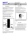
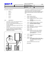
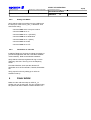
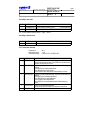
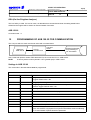
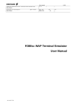
The light emitting diodes (LED) on the front of all
boards should light up in a certain way (see below), to
signal that the boards are working perfectly.
RASC requires some standard settings to start
working:
-the communication port must be set for 9600 baud
-the default password setting is 33333.
The LEDs at the top and front of a board
RED
Cordless System Manager Software requires:
YELLOW
-COM1 port default setting: 2400 baud
-the default password setting is AAAAAA
-printer port 2400 baud (X-on/X-off, 8 bits, 1 stop bit,
no parity).
Board position:
0 1 2 3
CPU-D
Connection
field 4
Cold
start strap
Connection
field 6
When the start-up is successfully completed, all LEDs
in the figure above are turned off. Proceed to section 4
on page 5.
3.3
/3
/4
/1
/2
/3
/4
RED LED
(cold start
indication)
EURO-connector
size 1/4
3.1
GREEN
Turn power on
Verify that the exchange has a power supply installed
for the correct mains voltage. Plug the power supply
cord into the mains outlet and switch on the power
supply or exchange.
Note:
COLD START
When invoking cold start all customer data
will be lost and all the announcements stored
on the VMU-D will be erased.
On the VMU-HD the announcements will be
kept but infos and messages will be lost.
Insert the cold restart-strap on CPU-D(_) in connection
field 6/1. Immediately after the power is turned on, the
red LED located above the strap should light. After a
few seconds the red LED at the top of the board
should go off and the yellow LED starts to flash.
Remove the restart-strap on CPU-D(_). This is to
prevent losing all system data if a restart should occur.
START OF OPERATION
Uppgjord/Prepared
Faktaansvarig - Subject responsible
5(12)
Dokumentnr/Documentnr
1537-ASB 150 02 Uen
Dokansv/Godkänd - Doc respons/Approved
4
Kontr/Checked
PROGRAMMING
THE SYSTEM
Start RASC and check if all the boards have been
detected. Then load the appropriate session for your
country containing the trunk’s transmission levels and
filter coefficients etc. (See RASC sessions for setting
of tone and transmission parameters).
After programming background music or music-onhold be sure to invoke a warm start to enable this
function.
4.1
Trunk programming
Trunk boards need special programming of the settings as required by the PTT network before the exchange can be used. In the RASC tool sessions are
available for the specific markets, setting certain transmission parameters and tone characteristics e.g. level,
cadences. Programming is executed with RASC. The
following groups of commands have to be provided
with proper values:
•
External line parameters (group 10)
•
Answer position for trunk lines (group 11)
•
Line signalling diagrams (group 12)
•
Register signalling diagrams (group 13)
The default values for trunk lines are 700 and
following. Route 0 is to access to trunk 700.
"9" is reserved for operator queue.
Refer to 1545-ASB15002Uen Fault Tracing
Instructions showing the BTU-D start-up sequence.
4.2
Tie line programming
Datum/Date
Rev
1999-08-10
G
Tillhör/Referens-File/Reference
Verify that the correct line signalling has been
selected. Refer to command 1201 and select:
8
9
10
11
Sweden E&M signalling
Continuous E&M sign., A-Format
Continuous E&M sign., D-Format
Discontinuous E&M signalling
44
45
46
CEPTL 1 (on BTU-E2)
CAILHO discontinuous
SSAC 15 - A (on BTU-E2)
If DTMF or MFC indialling is used, verify that a BTU-D
or REG board is installed in the system. The same
applies for the VMU-HD if the register function is
activated.
4.3
Programming the VMU HD
(hard disk)
The hard disk should be inserted following
prerequisites stated under section 5.3.2 on page 8.
After the update invoke the following commands:
4603
Enable data loading set to YES
4450
Load data after coldstart or board update.
Not used if data is just added.
Announcement groups
The available announcement groups are 4401 to 4426
with groups 4411 to 4426 being only available on the
VMU-HD.
4424
The VMU-HD has all 64 references while the
VMU-D provides only 32.
When invoking cold start or update card all data and
messages are deleted but not the announcements.
4.4
Number series
BTU-C/2
Verify that the correct line signalling has been
selected. Refer to command 1201 and select 12 for
DC-loop signalling.
If DID with DTMF or MFC is used check if a board with
register function is installed.
BTU-E
Verify that the far end has the same voice connection
selected (2- or 4-wire).
The completed exchange data sheets express the
customer’s requirements with respect to facilities and
number series. Program the system to the customer’s
requirements. On initialisation the first ELU-_ board
will acquire the extension numbers from 200 onward.
Note:
If the system does not start up successfully
and the red LEDs on nearly all cards are ON
then the PROMs on the CPU-D(_) could be
misplaced and must be corrected.
START OF OPERATION
Uppgjord/Prepared
Faktaansvarig - Subject responsible
6(12)
Dokumentnr/Documentnr
1537-ASB 150 02 Uen
Dokansv/Godkänd - Doc respons/Approved
5
Kontr/Checked
Datum/Date
Rev
1999-08-10
G
TEST PROCEDURES
The following test-procedures ensure the proper
functionality of the exchange.
5.1.1
Tillhör/Referens-File/Reference
Digital Telephones with/without
display
Digital telephones can be connected to either
ELU-D or ELU-C boards.
Start of test
5.1
Extension lines
This test verifies that the extension lines and the
telephones are connected and working.
a
Activity: Go to a telephone with display.
b
Activity: Read the display.
Check: Does the telephone show the correct
extension number?
c
Activity: Lift the handset.
Check: Does a dial tone sound?
d
Activity: Call an extension nearby and wait for it
to ring. Pick up the other telephone and
check for speech connection. Then
hang up both phones
Check: Have all extensions been tested? If the
answer is yes go to position f.
e
Activity: Go to next telephone and continue with
position b.
f
End of test.
MDF
5.1.2
Analogue Telephones
Analogue telephones are connected to an ELU-A
board.
To test proceed similar to the digital telephones.
The boards involved are:
•
ELU-A
•
ELU-C
•
ELU-D
5.2
Trunk lines
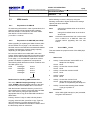
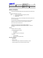
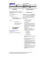
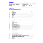
The test is designed to verify the connection between
ASB 150 02 and the public exchange and the
equipment for call metering is verified at the same time
The following functions are to be verified:
•
digit transmission
•
detection of external dial tone
•
voice transmission
•
detection of incoming call signal
•
call metering
START OF OPERATION
Uppgjord/Prepared
Faktaansvarig - Subject responsible
7(12)
Dokumentnr/Documentnr
1537-ASB 150 02 Uen
Dokansv/Godkänd - Doc respons/Approved
Kontr/Checked
The boards involved are:
5.2.1
•
BTU-A
•
BTU-A2
•
BTU-B
•
BTU-C
•
BTU-D
•
BTU-E
Datum/Date
Rev
1999-08-10
G
Tillhör/Referens-File/Reference
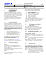
For the tests, it is desirable that the trunk lines have
individual call numbers in the public exchange.
If this is not the case, a line can be selected by seizing
all lines with the exception of the two used for each
test.
Start of test
a
Activity: A goes off hook.
Check: A receives dial tone.
b
Activity: A dials individual number of relevant
trunk line.
Check: A receives dial tone from public
exchange.
Preparations
•
Use RASC to read out the individual number of
the trunks connected to the system
c
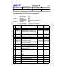
•
Connect a system telephone with display (A), to
any line in the MDF.
The telephone is permitted to initiate calls via all
trunk lines
Activity: A dials individual number of relevant
trunk line in public exchange.
Check: B receives external ring signal.
d
Activity: B answers.
Check: A-B speech connection established.
e
Activity: A and B goes on hook.
Check: None.
f
Activity: None.
Check: Have all trunk lines been utilised for
both incoming and outgoing calls?
If yes, go to position h, otherwise
go to position g.
g
Activity: Select next trunk line. Then go to
position a.
Check: None.
h
Activity: None.
Check: Verify that all metering pulses have
been registered on the trunk line meters
on the BTU-boards by using the
telephone.
i
Open all trunk lines that were seized.
•
Connect a system telephone with display (B), to
any line in the MDF. This telephone shall be
programmed as answer position for incoming
calls via all BTU boards.
Public
Network
MDF
End of test
START OF OPERATION
Uppgjord/Prepared
Faktaansvarig - Subject responsible
8(12)
Dokumentnr/Documentnr
1537-ASB 150 02 Uen
Dokansv/Godkänd - Doc respons/Approved
Kontr/Checked
Datum/Date
Rev
1999-08-10
G
Tillhör/Referens-File/Reference
5.3
VMU-boards
Before starting to record, change by using the
following commands to higher values as the storage
capacity has been extended.
5.3.1
Preparations for VMU-D
Commands
To avoid losing information in case of power failure, the
VMU-D board should be equipped with a battery,
RNV 991 942/001, connected to connection field 4.
See INSTALLATION INSTRUCTION,
(1531-BDV 113 08Uen.
4302
change from default value 12 seconds to
25 seconds
4303
change from default value 12 seconds to
25 seconds
Note:
5.3.2
Preparations for VMU-HD (hard disk)
When upgrading or replacing the VMU-D with a VMUHD see section 5.8 on page 11 for instructions. The
hard disk used on the VMU-HD is a standard PCMCIA
interface hard disk type III with a storage capacity
depending on the system demand.
Do not use a VMU-D and a VMU-HD in the same
system. When replacing the VMU-D in the same board
position with a VMU-HD follow instructions in section
5.8 on page 11. If the VMU-HD is placed in another
position use RASC to update both card positions.
5.3.3
Customer announcements can not be moved
from a VMU-D to a VMU-HD. Note the
contents before upgrading with the new
board.
Test of VMU-_ board
This test verifies the proper function of the VMU-(H)D
board(s).
Start of test
a
Activity: Press the button named INFO on a
telephone with display.
Check: None.
b
Activity: Choose the function LEAVE.
Check: None.
c
Activity: Choose the function VOICE.
Check: None.
d
Activity: Speak.
Check: None.
RASC menu for handling VMU-HD data files
e
The menu VMU-HD Dumping/Loading is located
under OTHER. If files are already stored on the hard
disk this utility lists all available files on the screen.
Activity: Choose the function PLAY.
Check: Verify that what you have said at
position d is repeated by the telephone.
f
Activity: Have all VMU-board(s) been tested?
If yes go to position h.
The following DOS directories must be created on this
hard disk (use a PC):
\Info0
\Info1
\message2
\message3
\message4
\message5
\anno0
\anno1
\anno2
\anno3
\annoF
With the ID button select the directory on the PC in
which RASC has to search and list the VMU-HD data
files. Then select by using the space bar the
appropriate files to copy to the VMU-HD hard disk or
delete them.
Printing: use the F4 key to make a file list printout.
Copying: select the files, press F8 to copy. Type the
drive and directory. Prompts will be given if the
directory is not available and should be created. Also if
the file already exists to overwrite it.
End of test
Note:
When VMU-(H)D board(s) is (are) activated,
the green LED will be lit.
START OF OPERATION
Uppgjord/Prepared
Faktaansvarig - Subject responsible
9(12)
Dokumentnr/Documentnr
1537-ASB 150 02 Uen
Dokansv/Godkänd - Doc respons/Approved
5.4
Kontr/Checked
CORDLESS
Datum/Date
Rev
1999-08-10
G
3.
Verify that the wiring to the Base Stations is correct.
Visual Checks
The power LED on every Base Station should be ON.
The LEDs on the IC-CU and IC-LU boards should be
OFF.
Note:
Every Base Station accessible by persons
other than trained personnel must have the
cover mounted.
Test of the cordless
With the aid of the INTEGRATED CORDLESS
SYSTEM MANAGER verify that the correct
programming has been performed and using the
systems menu check the status of the boards and
Base Stations. The following test verifies the proper
function of the INTEGRATED CORDLESS system.
b
c
Move close to each Base Station and check that
the portable locks to it (the Service Display
should display the correct Base Station
number).
After having checked that all Base Stations are
operational proceed with the area coverage test.
Start of Area Coverage test
The purpose of this test is to verify that there is
satisfactory field strength to enable good speech
quality everywhere within the covered area (rooms,
elevator shafts, staircases). This test is executed with
two portables and requires two persons.
1.
Activity: Use a DT360 (or DT310) and dial an
extension with display near by.
Check: None.
Place the portable in the Service Display mode
and call the other portable. One user of the
portable should now start moving around the
covered area. Both users must check that a
good speech quality is maintained everywhere.
Special attention should be paid to areas such
as edges of the building and areas behind metal
structures where there is a possibility of reduced
speech quality.
2.
Activity: Check that the correct calling extension
number is displayed and pick up the
ringing phone.
Check: If voice connection has been
established.
Mark areas where RQI is not stable on 20hex
and where cracking sounds or mutes are heard.
A further Base Station should be installed in this
area.
Portable Checks
Start of test
a
Tillhör/Referens-File/Reference
Activity: Put both telephone sets on hook.
Check: None.
End of test
Radio Coverage Checks
This test checks for each portable the complete
connection from system board to PABX. Furthermore it
checks that the portables' numbers have been
correctly programmed. The test is performed by calling
all portables from one and the same portable.
1.
Put all portables together in order of extension
number on a table.
2.
Go off-hook with each portable and check that
the dial tone is heard.
3.
Call with a portable (portable A) all other
portables sequentially and check that the
portable with the corresponding number on its
display rings when called.
4.
Call portable A and check if it rings.
The radio coverage verification consists of two tests:
-
Base Station test,
-
Area coverage test.
Start of Base Station test
The purpose of this test is to check if all Base Stations
are operational.
1.
Put a portable in the Service Display mode
(refer to the FAULT TRACING 1545ASB15002Uen).
2.
Take ground plan (map) of the building where
the Base Stations are indicated with their
corresponding Base Station number.
START OF OPERATION
Uppgjord/Prepared
Faktaansvarig - Subject responsible
10(12)
Dokumentnr/Documentnr
1537-ASB 150 02 Uen
Dokansv/Godkänd - Doc respons/Approved
Kontr/Checked
Feature Enabling Control Unit (FECU)
On cold start the IC-CU recognizes whether a FECU is
connected and how many portables are allowed to be
connected to the cordless. The FECU must not be
unplugged during operation as after a certain time out
only the first 8 portables are recognized (default
value).
To up/down grade:
a
save configuration by RASC menu
’Transfer to file’
b
replace FECU
c
invoke warm start (manually or by RASC)
d
update HW configuration in RASC (off-line
mode)
e
update the RP configuration (online mode)
f
IC-CU reports new amount of portables
g
recover initial configuration.
5.5
CPU-D(_)
Possible connections to CPU-D(_) are:
•
lowest V.24 (Used by RASC) and on
CPU-D(_) two additional ports for
applications are available
•
audio input
•
temperature probe inputs
Feature Enabling Control Unit
The CPU-D4 recognizes whether a FECU is
connected and which application is enabled. The
FECU must not be unplugged during operation (only
the basic functionnality is available without FECU) as
the system checks periodically its presence. This
might cause a slight delay after plugging in until the
FECU is detected.
Datum/Date
Rev
1999-08-10
G
5.5.1
Tillhör/Referens-File/Reference
Test of V.24
If a connection can be established by RASC and a PC
connected to CPU-D(_) then the V.24 is working.
Otherwise use a data line tester to check for
communication faults.
5.5.2
Test of temperature probe input
Start of test
a
Activity: Read the temperature on a telephone.
Check: Verify that the temperature is correct.
End of test
START OF OPERATION
Uppgjord/Prepared
Faktaansvarig - Subject responsible
11(12)
Dokumentnr/Documentnr
1537-ASB 150 02 Uen
Dokansv/Godkänd - Doc respons/Approved
5.6
Kontr/Checked
System clock
Set the correct time and day by using the RASC
maintenance program and verify it on the display of a
digital telephone set.
Datum/Date
Rev
1999-08-10
G
5.9
CTI
5.9.1
Installation on Novell® Netware server
Note:
5.7
Handling/exchanging boards
while the system is in operation
While the exchange is in operation an upgrading by
new boards (system expansion) or replacment of
boards with the same configuration is supported. Care
must be taken to extract and replace the board without
metal parts touching adjacent boards and thus causing
a short circuit. This may permanently destroy
electronic components on the board being extarcted or
boards remaining in the system. Use RASC to verify
whether the system logged the board replacement.
5.8
Upgrading or exchanging
boards
When upgrading or replacing boards e.g.the VMU-D
with a VMU-HD. Use RASC to take the old board out of
system evidence and replace it with the new board.
Switch the system OFF and take out the board
and then switch ON again to start up the
exchange. Start RASC and perform board
update to remove board from system. Then
switch OFF exchange.
Insert VMU-HD and switch ON the exchange.
Use RASC to perform board update.
The same procedure applies when replacing a
subequipped board with a standard one.
Tillhör/Referens-File/Reference
All activities on a customer server have to be
carried out by a qualified and authorized
network administrator. Ericsson cannot be
held responsible for failure, inoperability or
unavailability of the server nor for hardware
incompatibility.
To enable this function please verify that Novell® 3.x or
4.10 or higher has been installed properly on the
Network.
Check that the server is installed correctly and that
Novell’s®Telephony Services is loaded.
The following load instruction will be performed
automatically in the next release:
Load module aiocomx and choose which serial
communication board is to be used by loading the
module with a suitable syntax using command:
load aiocomx port=___ int=_
The hardware of the serial COM port must offer the
capability of transferring data with 19.200 baud (this
should be possible if the board uses the IC 16550).
Install the BP250drv.nlm and load it by using
command:
load bpdrv
To make sure that the server activates this application
during start-up add the two commands stated above to
the autoexec.ncf on the server.
Verify that the users are registered for log on to the
server. Use TAdmin to register the users for Telephony
Services.
START OF OPERATION
Uppgjord/Prepared
Faktaansvarig - Subject responsible
12(12)
Dokumentnr/Documentnr
1537-ASB 150 02 Uen
Dokansv/Godkänd - Doc respons/Approved
5.9.2
Kontr/Checked
Setting with RASC
Verify that the cable connection from the COM port to
the V.24 port of the CPU-D_/Aux_ is attached. Then
enter RASC using:
command 8901 which V.24 port is active
command 6006 set to 11
command 6007 set to 1 (US-ACII)
command 6009 set to 9600 baud
command 6010 set to 1 (slave)
command 6011 set to NO
command 6012 set to CTI.
5.9.3
Installation on client PC
Install the Telephony Services for clients (necessary to
provide the application with the CSTA.dll to establish
communication). Refer to the Novell® handbook.
Verify that the users are registered for log on to the
Telephony Services. Then log on to the telephony
server.
First start Windows, then start the desired CTI
application such as PhoneTastic, FastCall, PhoneMax
etc.
Verify proper function by setting up a call to an
extension near by.
6
FINAL WORK
Make sure the cold start-strap on CPU-D(_) in
position 4/4 or 6/1is removed. This is to prevent losing
all system and VMU-D data if a restart should occur.
Datum/Date
Rev
1999-08-10
G
Tillhör/Referens-File/Reference
DIRECTION OF USE
Uppgjord/Prepared
Faktaansvarig - Subject responsible
SEA/EBBMP M. Plattner
SEA/EBAX/E
Dokansv/Godkänd - Doc respons/Approved
SEA/EBBMP
1(11)
Dokumentnr/Documentnr
1553-ROF 157 5126 Uen
Kontr/Checked
Datum/Date
Rev
Tillhör/Referens-File/Reference
1999-08-16
B
ASB 150 02
Database reference
1553-ROF 157 5126 Uen-1-B.fm
BusinessPhone 50
BusinessPhone 250
VMU-HD-TEXTS
Contents
Page
GENERAL INFORMATION. . . . . . . . . . . . . . . . . . . . . . . . . . . . . . . . . . . . . . . . . . . . . . . . . . . 2
Title 1:Predefined Information Texts . . . . . . . . . . . . . . . . . . . . . . . . . . . . . . . . . . . . . . . . . . . . 3
Title 2: Months . . . . . . . . . . . . . . . . . . . . . . . . . . . . . . . . . . . . . . . . . . . . . . . . . . . . . . . . . . . . 3
Title 3: Days . . . . . . . . . . . . . . . . . . . . . . . . . . . . . . . . . . . . . . . . . . . . . . . . . . . . . . . . . . . . . . 3
Title 4:Hours . . . . . . . . . . . . . . . . . . . . . . . . . . . . . . . . . . . . . . . . . . . . . . . . . . . . . . . . . . . . . . 4
Title 5: 5 Minutes . . . . . . . . . . . . . . . . . . . . . . . . . . . . . . . . . . . . . . . . . . . . . . . . . . . . . . . . . . 5
Title 6: General Announcements . . . . . . . . . . . . . . . . . . . . . . . . . . . . . . . . . . . . . . . . . . . . . . 5
Title 7: Automated Attendant . . . . . . . . . . . . . . . . . . . . . . . . . . . . . . . . . . . . . . . . . . . . . . . . . 6
Title 8: Mailbox System - Storing & Retrieving voice message prompts. . . . . . . . . . . . . . . . . 7
Title 9: Mailbox System - Storing of individual messages. . . . . . . . . . . . . . . . . . . . . . . . . . . . 8
Title 10: Mailbox System - Retrieving of individual messages . . . . . . . . . . . . . . . . . . . . . . . . 8
Title 11: Mailbox System - Storing of common messages . . . . . . . . . . . . . . . . . . . . . . . . . . . 8
Title 12: Mailbox System - Retrieving of common messages . . . . . . . . . . . . . . . . . . . . . . . . . 8
Title 13: Mailbox System - Digits . . . . . . . . . . . . . . . . . . . . . . . . . . . . . . . . . . . . . . . . . . . . . . 9
Title 14: Mailbox System - Common voice prompts . . . . . . . . . . . . . . . . . . . . . . . . . . . . . . . . 9
Title 15: DISA Voice prompts . . . . . . . . . . . . . . . . . . . . . . . . . . . . . . . . . . . . . . . . . . . . . . . . 10
Title 16: Trunk Exit-position. . . . . . . . . . . . . . . . . . . . . . . . . . . . . . . . . . . . . . . . . . . . . . . . . . 10
Title 17: ACD greeting announcements . . . . . . . . . . . . . . . . . . . . . . . . . . . . . . . . . . . . . . . . 10
Title 18: CTI-AA voice prompts. . . . . . . . . . . . . . . . . . . . . . . . . . . . . . . . . . . . . . . . . . . . . . . 11
Title 19: Integrated Music-on-hold prompts . . . . . . . . . . . . . . . . . . . . . . . . . . . . . . . . . . . . . 11
Title 20: Personal Greeting voice prompts . . . . . . . . . . . . . . . . . . . . . . . . . . . . . . . . . . . . . . 11
Specification for storing voice prompts from the telephone
without using the program WAV2VMU . . . . . . . . . . . . . . . . . . . . . . . . . . . . . . . . . . . . . . . . . 11
DIRECTION OF USE
Uppgjord/Prepared
Faktaansvarig - Subject responsible
2(11)
Dokumentnr/Documentnr
1553-ROF 157 5126 Uen
Dokansv/Godkänd - Doc respons/Approved
Kontr/Checked
Datum/Date
Rev
1999-08-16
B
Tillhör/Referens-File/Reference
GENERAL INFORMATION
The PC-program WAV2VMU.EXE (LZYBS 203 2248) converts audiofiles from WAV to VMU-HD format.
Usage:
WAV2VMU <filename[.WAV]> /option1 /option2
options:
/L
converts to VMU-HD low quality format (high quality is default)
/C
cuts frequencies below 250 Hertz
/+
output file + 6 dB
Recording the voice prompts the name of the <filename[.WAV]> should be according to the lists in this
document (see following pages).
E.g.:The voice prompt „I am absent at the moment and will be back at“ should be recorded as
„D031D031.wav“ and will be converted and renamed by the program to „D031D031.001“.
After a successful conversion a file with the name
-<filename.000> Voice storage capacity: VMU-HD Low Quality ( 32 Kbits/sec.)
-<filename.001> Voice storage capacity: VMU-HD High Quality ( 64 Kbits/sec.)
will be created.
or
=default value
Limitations:
•
Wildcards in <filename> are not allowed.
•
Only certain WAV formats will be supported:
•
•
8 or 16 bit samples
•
mono or stereo
•
11.025 kHz, 22.05 kHz or 44.1 kHz sample rate
Not supported:
•
•
4 bit & 12 bit samples
all kind of audio codes (compressed formats)
Minimum PC configuration:
•
486DX2 66 MHz
•
MS-DOS 5.0 or higher
•
It is possible to use this program in a MS-DOS box from MS-Windows 3.x or higher.
•
A PCMCIA (PC-CARD) type III slot is necessary for file transfer to VMU-HD.
DIRECTION OF USE
Uppgjord/Prepared
Faktaansvarig - Subject responsible
3(11)
Dokumentnr/Documentnr
1553-ROF 157 5126 Uen
Dokansv/Godkänd - Doc respons/Approved
Kontr/Checked
Datum/Date
Rev
1999-08-16
B
Tillhör/Referens-File/Reference
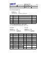
Title 1:Predefined Information Texts
Command no.:
Valid number range:
Valid filename range:
Number
Filename
1
2
3
4
5
6
D031D031.001
D032D032.001
D033D033.001
D034D034.001
D035D035.001
D036D036.001
4402
1-7
D031D031.001 - D037D037.001
Predefined texts
I’m absent at the moment and will be back at
I’m on a business trip and will be back on, the
I’m having lunch and will be back at
I’m in a meeting and will be back at
I’m on vacation and will be back on, the
I’m ill. I will probably be back on, the
( + time )
( + date )
( + time )
( + time )
( + date )
( + date )
e.g.: "I’m ill. I will probably be back on, the " - "First of" - "January"
e.g.: "I’m in a meeting and will be back at" - "Eight" - "oh clock"
e.g.: "I’m absent at the moment and will be back at" - "Nine" - "oh five"
Title 2: Months
Command no.:
Valid number range:
Valid filename range:
Number
1
2
3
4
5
6
7
8
9
10
11
12
Title 3: Days
4403
1 - 12
D041D041.001
- D04CD04C.001
Filename
D041D041.001
D042D042.001
D043D043.001
D044D044.001
D045D045.001
D046D046.001
D047D047.001
D048D048.001
D049D049.001
D04AD04A.001
D04BD04B.001
D04CD04C.001
Predefined texts
January
February
March
April
May
June
July
August
September
October
November
December
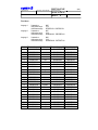
Command no.:
4404
Valid number range: 1 - 31
Valid filename range: D051D051.001
- D06FD06F.001
Number
1
2
3
4
5
6
7
8
9
:
:
31
Filename
D051D051.001
D052D052.001
D053D053.001
D054D054.001
D055D055.001
D056D056.001
D057D057.001
D058D058.001
D059D059.001
:
:
D06FD06F.001
Predefined texts
First of
Second of
Third of
Fourth of
Fifth of
Sixth of
Seventh of
Eighth of
Ninth of
:
:
Thirty-first of
DIRECTION OF USE
Uppgjord/Prepared
Faktaansvarig - Subject responsible
4(11)
Dokumentnr/Documentnr
1553-ROF 157 5126 Uen
Dokansv/Godkänd - Doc respons/Approved
Kontr/Checked
Datum/Date
Rev
1999-08-16
B
Tillhör/Referens-File/Reference
Title 4:Hours
Language 1:
Command no.
Valid number range:
Valid filename range:
4405
0 - 23
D070D070.001 - D087D087.001
Language 2:
Command no.:
Valid number range:
Valid filename range:
4407
0 - 23
D0A0D0A0.001 - D0B7D0B7.001
Language 3:
Command no.:
Valid number range:
Valid filename range:
4409
0 - 23
D0D0D0D0.001 - D0E7D0E7.001
Number Filename language 1Predefined textsFilename language 2 Filename language 3
0
D070D070.001
midnight
D0A0D0A0.001
D0D0D0D0.001
1
D071D071.001
one
D0A1D0A1.001
D0D1D0D1.001
2
D072D072.001
two
D0A2D0A2.001
D0D2D0D2.001
3
D073D073.001
three
D0A3D0A3.001
D0D3D0D3.001
4
D074D074.001
four
D0A4D0A4.001
D0D4D0D4.001
5
D075D075.001
five
D0A5D0A5.001
D0D5D0D5.001
6
D076D076.001
six
D0A6D0A6.001
D0D6D0D6.001
7
D077D077.001
seven
D0A7D0A7.001
D0D7D0D7.001
8
D078D078.001
eight
D0A8D0A8.001
D0D8D0D8.001
9
D079D079.001
nine
D0A9D0A9.001
D0D9D0D9.001
10
D07AD07A.001
ten
D0AAD0AA.001
D0DAD0DA.001
11
D07BD07B.001
eleven
D0ABD0AB.001
D0DBD0DB.001
12
D07CD07C.001
twelve
D0ACD0AC.001
D0DCD0DC.001
13
D07DD07D.001
thirteen
D0ADD0AD.001
D0DDD0DD.001
14
D07ED07E.001
fourteen
D0AED0AE.001
D0DED0DE.001
15
D07FD07F.001
fifteen
D0AFD0AF.001
D0DFD0DF.001
16
D080D080.001
sixteen
D0B0D0B0.001
D0E0D0E0.001
17
D081D081.001
seventeen
D0B1D0B1.001
D0E1D0E1.001
18
D082D082.001
eighteen
D0B2D0B2.001
D0E2D0E2.001
19
D083D083.001
nineteen
D0B3D0B3.001
D0E3D0E3.001
20
D084D084.001
twenty
D0B4D0B4.001
D0E4D0E4.001
21
D085D085.001
twenty-one
D0B5D0B5.001
D0E5D0E5.001
22
D086D086.001
twenty-two
D0B6D0B6.001
D0E6D0E6.001
23
D087D087.001
twenty-three
D0B7D0B7.001
D0E7D0E7.001
DIRECTION OF USE
Uppgjord/Prepared
Faktaansvarig - Subject responsible
5(11)
Dokumentnr/Documentnr
1553-ROF 157 5126 Uen
Dokansv/Godkänd - Doc respons/Approved
Kontr/Checked
Datum/Date
Rev
1999-08-16
B
Tillhör/Referens-File/Reference
Title 5: 5 Minutes
Language 1:
Command no.:
Valid number range:
Valid filename range:
4406
0 - 11
D090D090.001 - D09BD09B.001
Language 2:
Command no.:
Valid number range:
Valid filename range:
4408
0 - 11
D0C0D0C0.001 - D0CBD0CB.001
Language 3:
Command no.:
Valid number range:
Valid filename range:
4410
0 - 11
D0F0D0F0.001 - D0FBD0FB.001
Number
0
1
2
3
4
5
6
7
8
9
10
11
Filename language 1 Predefined texts
D090D090.001
hundred hours
D091D091.001
oh five
D092D092.001
ten
D093D093.001
fifteen
D094D094.001
twenty
D095D095.001
twenty-five
D096D096.001
thirty
D097D097.001
thirty-five
D098D098.001
forty
D099D099.001
forty-five
D09AD09A.001
fifty
D09BD09B.001
fifty-five
Filename language 2 Filename language 3
D0C0D0C0.001
D0F0D0F0.001
D0C1D0C1.001
D0F1D0F1.001
D0C2D0C2.001
D0F2D0F2.001
D0C3D0C3.001
D0F3D0F3.001
D0C4D0C4.001
D0F4D0F4.001
D0C5D0C5.001
D0F5D0F5.001
D0C6D0C6.001
D0F6D0F6.001
D0C7D0C7.001
D0F7D0F7.001
D0C8D0C8.001
D0F8D0F8.001
D0C9D0C9.001
D0F9D0F9.001
D0CAD0CA.001
D0FAD0FA.001
D0CBD0CB.001
D0FBD0FB.001
Title 6: General Announcements
Command no.:
Valid number range:
Valid filename range:
4401
1 - 32
D001D001.001 - D020D020.001
Possibility 1: ACD texts
Number
Filename
Predefined texts
1
2
D001D001.001
D002D002.001
All agents are busy. Your call is number ...
... in the queue. Please hold.
3
D003D003.001
4
D004D004.001
All agents are busy.
Your approximate waiting time is ...
... minutes. Please hold.
( + position )
( + time )
e.g. "All agents are busy. Your call is number" - "Five" - "in the queue. Please hold"
e.g. "All agents are busy. Your approximate waiting time is" - " Ten" - "minutes. Please hold"
DIRECTION OF USE
Uppgjord/Prepared
Faktaansvarig - Subject responsible
6(11)
Dokumentnr/Documentnr
1553-ROF 157 5126 Uen
Dokansv/Godkänd - Doc respons/Approved
Kontr/Checked
Datum/Date
Rev
1999-08-16
B
Tillhör/Referens-File/Reference
Possibility 2: Hotel texts
Number
Filename
5
6
D005D005.001
D006D006.001
Predefined texts
You have ordered a wake-up call for ...
Good morning, this is your wake-up call.
( + time of wake up)
e.g. "You have ordered a wake-up call for" - "eight" - "Oh five"
Possibility 3: Business texts
Number
7
Filename
D007D007.001
Predefined texts
This is your reminder call.
Title 7: Automated Attendant
Command no.:
Valid number range:
Valid filename range:
No.
1
Filename
D101D101.001
2
D102D102.001
3
D103D103.001
4
D104D104.001
42
D12AD12A.001
4411
1 - 42
D101D101.001 - D12AD12A.001
Customer specific texts
Welcome to the Automated Attendant. Please press ONE to dial
directly to the extension number. Press STAR to be connected to the
operator. Please make your choice.
Welcome to the Automated Attendant. Select from the following possibilities:
Press ONE for the marketing department.
Press TWO for the customer service.
Press THREE for other departments. Please make your choice.
Welcome to the Automated Attendant. Select from the following possibilities:
Press ONE for the purchasing department.
Press TWO for the accounts department.
Press THREE for other departments.
Press STAR to be connected to the operator. Please make your
choice.
Welcome to the Automated Attendant.
Please dial the extension number you want to be connected to.
The dialled number is wrong.
DIRECTION OF USE
Uppgjord/Prepared
Faktaansvarig - Subject responsible
7(11)
Dokumentnr/Documentnr
1553-ROF 157 5126 Uen
Dokansv/Godkänd - Doc respons/Approved
Kontr/Checked
Datum/Date
Rev
1999-08-16
B
Tillhör/Referens-File/Reference
Title 8: Mailbox System - Storing & Retrieving voice message prompts
Language 1:
Language 2:
Language 3:
Command no.:
Valid number range:
Valid filename range:
Command no.:
Valid number range:
Valid filename range:
Command no.:
Valid number range:
Valid filename range:
4412
0 - 14
D130D130.001 - D13ED13E.001
4413
0-6
D140D140.001 - D146D146.001
4414
0-6
D150D150.001 - D156D156.001
No
Filename
Predefined texts
language 1
0 D130D130.001 After the tone, please record your message.
1 D131D131.001 To replay, press ONE, - For the next message, press TWO, - To delete it and call the
extension, press STAR, - to delete it, press
HASH.
2 D132D132.001 To replay, press ONE, - For the next message, press TWO, - To delete it, press HASH.
3 D133D133.001 Message deleted.
4 D134D134.001 Call back message from:
( + number )
5 D135D135.001 End of messages. Good-Bye.
6 D136D136.001 At the moment, your mailbox is being consulted. Please call back later.
7 D137D137.001 To leave a message in the mailbox press
NINE, or wait, - For assistance, press STAR.
8 D138D138.001 Please enter your mailbox number, - For
assistance, press STAR.
9 D139D139.001 Enter your extension number, to access the
common mailbox, - For assistance, press
STAR.
10 D13AD13A.001 The extension has no access to the common
mailbox.
11 D13BD13B.001 Welcome to mailbox ...
12 D13CD13C.001 If this is correct, press STAR, - To select
another mailbox, press HASH.
13 D13DD13D.001 The desired extension has no mailbox.
14 D13ED13E.001 The desired mailbox does not exist.
Filename
Filename
language 2
language 3
D140D140.001 D150D150.001
D141D141.001 D151D51.001
D142D142.001 D152D152.001
D143D143.001
D144D144.001
D145D145.001
D146D146.001
D153D153.001
D154D154.001
D155D155.001
D156D156.001
DIRECTION OF USE
Uppgjord/Prepared
Faktaansvarig - Subject responsible
8(11)
Dokumentnr/Documentnr
1553-ROF 157 5126 Uen
Dokansv/Godkänd - Doc respons/Approved
Kontr/Checked
Datum/Date
Rev
1999-08-16
B
Tillhör/Referens-File/Reference
Title 9: Mailbox System - Storing of individual messages
Command no.:
Valid number range:
Valid filename range:
Number
Filename
0
D160D160.001
1
D161D161.001
4415
0 - 31
D160D160.001 - D17FD17F.001
Customer specific text
Welcome to the mailbox-system.
The desired extension ...
... has activated the mailbox.
Title 10: Mailbox System - Retrieving of individual messages
Command no.:
Valid number range:
Valid filename range:
Number
0
Filename
D180D180.001
4416
0 - 15
D180D180.001 - D18FD18F.001
Customer specific text
Welcome to your Mailbox System.
Title 11: Mailbox System - Storing of common messages
Command no.:
Valid number range:
Valid filename range:
Number
0
Filename
D190D190.001
4417
0 - 15
D190D190.001 - D19FD19F.001
Predefined text
Welcome to the common mailbox.
Title 12: Mailbox System - Retrieving of common messages
Command no.:
Valid number range:
Valid filename range:
Number
0
Filename
D1A0D1A0.001
4418
0 - 15
D1A0D1A0.001 - D1AFD1AF.001
Customer specific text
Welcome to your Mailbox System.
( + number )
DIRECTION OF USE
Uppgjord/Prepared
Faktaansvarig - Subject responsible
9(11)
Dokumentnr/Documentnr
1553-ROF 157 5126 Uen
Dokansv/Godkänd - Doc respons/Approved
Kontr/Checked
Datum/Date
Rev
1999-08-16
B
Tillhör/Referens-File/Reference
Title 13: Mailbox System - Digits
Language 1:
Command no.:
Valid number range:
Valid filename range:
4419
0-9
D1B0D1B0.001 - D1B9D1B9.001
Language 2:
Command no.:
Valid number range:
Valid filename range:
4420
0-9
D1C0D1C0.001 - D1C9D1C9.001
Language 3:
Command no.:
Valid number range:
Valid filename range:
4421
0-9
D1D0D1D0.001 - D1D9D1D9.001
Number
0
1
2
3
4
5
6
7
8
9
Filename
language 1
D1B0D1B0.001
D1B1D1B1.001
D1B2D1B2.001
D1B3D1B3.001
D1B4D1B4.001
D1B5D1B5.001
D1B6D1B6.001
D1B7D1B7.001
D1B8D1B8.001
D1B9D1B9.001
Predefined texts
Zero
One
Two
Three
Four
Five
Six
Seven
Eight
Nine
Filename
language 2
D1C0D1C0.001
D1C1D1C1.001
D1C2D1C2.001
D1C3D1C3.001
D1C4D1C4.001
D1C5D1C5.001
D1C6D1C6.001
D1C7D1C7.001
D1C8D1C8.001
D1C9D1C9.001
Filename
language 3
D1D0D1D0.001
D1D1D1D1.001
D1D2D1D2.001
D1D3D1D3.001
D1D4D1D4.001
D1D5D1D5.001
D1D6D1D6.001
D1D7D1D7.001
D1D8D1D8.001
D1D9D1D9.001
Title 14: Mailbox System - Common voice prompts
Command no.:
Valid number range:
Valid filename range:
Number
0
1
2
Filename
D1E0D1E0.001
D1E1D1E1.001
D1E2D1E2.001
4422
0-2
D1E0D1E0.001 - D1E2D1E2.001
Predefined texts
Please enter your password.
Password incorrect.
The password is still incorrect.
The access to the mailbox is denied. Good-Bye.
DIRECTION OF USE
Uppgjord/Prepared
Faktaansvarig - Subject responsible
10(11)
Dokumentnr/Documentnr
1553-ROF 157 5126 Uen
Dokansv/Godkänd - Doc respons/Approved
Kontr/Checked
Datum/Date
Rev
1999-08-16
B
Tillhör/Referens-File/Reference
Title 15: DISA Voice prompts
Command no.:
Valid number range:
Valid filename range:
Number
0
1
2
3
4
5
6
7
8
9
4423
0-9
D1F0D1F0.001 - D1F9D1F9.001
Filename
Predefined texts
D1F0D1F0.001 Please enter the desired extension number or press STAR for
assistance.
D1F1D1F1.001 Please enter your password.
D1F2D1F2.001 To classify the call, enter the account code and confirm with
HASH, - Or to continue without classifying press HASH now.
D1F3D1F3.001 When you hear the dial tone, enter the trunk access code and the
desired external number.
D1F4D1F4.001 The desired extension does not exist.
Please try again.
D1F5D1F5.001 The desired extension is not allowed to use the DISA function.
Thank you for calling. Good-Bye.
D1F6D1F6.001 The trunk line you’ve dialled is not related to your company.Please
retry and use the correct public number for your traffic group.
Thank you for calling. Good-Bye.
D1F7D1F7.001 Password incorrect. Please try again.
D1F8D1F8.001 You have entered more than 15 digits. Please try again.
D1F9D1F9.001 Welcome to the DISA system.
Title 16: Trunk Exit-position
Command no.:
Valid number range:
Valid filename range:
Number
0
Filename
D200D200.001
1
D201D201.001
4424
0 - 31on VMU-D
0 - 63 on VMU-HD
D200D200.001-D21FD21F.001 on VMU-D
D200D200.001-D23FD23F.001 on VMU-HD
Customer specific texts
Sorry, all agents are busy at the moment. Your call will be placed in
a queue. Please hold.
You’re calling outside office hours. However, all agents are busy at
the moment. Your call will be placed in a queue. Please hold.
Title 17: ACD greeting announcements
Command no.:
Valid number range:
Valid filename range:
4425
1 - 255
D300D300.001 - D3FED3FE.001
DIRECTION OF USE
Uppgjord/Prepared
Faktaansvarig - Subject responsible
11(11)
Dokumentnr/Documentnr
1553-ROF 157 5126 Uen
Dokansv/Godkänd - Doc respons/Approved
Kontr/Checked
Datum/Date
Rev
1999-08-16
B
Tillhör/Referens-File/Reference
Title 18: CTI-AA voice prompts
Command no.:
Valid number range:
Valid filename range:
4426
1 - 24
D401D401.001 - D418D418.001
Title 19: Integrated Music-on-hold prompts
Command no.:
Valid number range:
Valid filename range:
4427
0 - 15
D420D420.001 - D42FD42F.001
Title 20: Personal Greeting voice prompts
Command no.:
Valid number range:
Valid filename range:
4428
1-8
D440D440.001 - D448D448.001
Number
0
Filename
D440D440.001
Predefined texts
Main Menu: - To listen to your messages, press ONE, - To configure the mailbox press TWO.
1
D441D441.001
Configuration Menu: - To configure your personal greeting, when the line
is busy, press ONE, - On no reply, press TWO, - For direct diversion,
press THREE, - to go back to the main menu, press Oh (0).
2
D442D442.001
Greeting Menu: - To record your personal greeting, press ONE, to finish
recording, press HASH, -To listen to your personal greeting, press TWO,
- To delete it, press THREE, - To go back to the configuration menu,
press NINE, - Or to go back to the main menu, press Oh (0).
3
4
5
6
7
8
D443D443.001
D444D444.001
D445D445.001
D446D446.001
D447D447.001
D448D448.001
This feature is currently not available, please try again later.
Recording time exceeded. Your greeting has not been recorded.
No greeting recorded.
Greeting recorded.
Greeting deleted.
End of messages. - To go back to the main menu, press Oh (0), to exit, hang up.
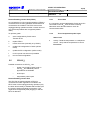
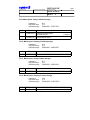
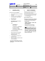
Specification for storing voice prompts from the telephone
without using the program WAV2VMU
Title 16: Trunk Exit-position
Start of title
--- bar --- break: 2 seconds
--- bar --- break: 2 seconds
bar
---text-----text---
break: 3 seconds
break: 3 seconds
bar
break
2 seconds
text
break
3 seconds
bar
break
2 seconds
text
break
3 seconds
START OF OPERATION
Uppgjord/Prepared
Faktaansvarig - Subject responsible
SEA/EBBMP Stangelberger SEA/EBBS
Dokansv/Godkänd - Doc respons/Approved
SEA/EBBMP
1(17)
Dokumentnr/Documentnr
2/1537-ASB 150 02 Uen
Kontr/Checked
Datum/Date
Rev
Tillhör/Referens-File/Reference
99-07-15
H
ASB 150 02
Database reference
1537_2.fm
START OF OPERATION
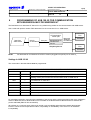
COMMUNICATION WITH APPLICATION PRODUCTS
This document describes how to connect peripheral equipment via V.24 ports to the PBX system ASB150 02
and the relevant commands to program the PBX for different applications.
Contents
Page
1
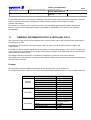
GENERAL . . . . . . . . . . . . . . . . . . . . . . . . . . . . . . . . . . . . . . . . . . . . . . . . . . . . . . . . . . . . . . . . . . . . . . . 2
1.1
Supplementary documents. . . . . . . . . . . . . . . . . . . . . . . . . . . . . . . . . . . . . . . . . . . . . . . . . . . . . . . . . . . 2
1.2
Product numbers . . . . . . . . . . . . . . . . . . . . . . . . . . . . . . . . . . . . . . . . . . . . . . . . . . . . . . . . . . . . . . . . . . 2
2
INSTALLATION . . . . . . . . . . . . . . . . . . . . . . . . . . . . . . . . . . . . . . . . . . . . . . . . . . . . . . . . . . . . . . . . . . . 3
2.1
Pin connectors for V.24 I/O-ports . . . . . . . . . . . . . . . . . . . . . . . . . . . . . . . . . . . . . . . . . . . . . . . . . . . . . . 3
3
COMMANDS FOR PROGRAMMING OF ASB 150 02 FOR PERIPHERAL COMMUNICATION . . . . . 4
3.1
Command overview, local connection via V.24 ports . . . . . . . . . . . . . . . . . . . . . . . . . . . . . . . . . . . . . . . 4
3.2
Commands used for programming of ASB 150 02 for input/output of CIL and HOTEL DATA . . . . . . . . 5
4
PROGRAMMING OF THE ASB 150 02 FOR COMMUNICATION WITH RASC / CMG . . . . . . . . . . . . 5
5
PRINTOUT OF TELEPHONE DIRECTORY. . . . . . . . . . . . . . . . . . . . . . . . . . . . . . . . . . . . . . . . . . . . . . 6
6
PROGRAMMING OF ASB 150 02 FOR COMMUNICATION
WITH CALLCENTRE SUPERVISOR. . . . . . . . . . . . . . . . . . . . . . . . . . . . . . . . . . . . . . . . . . . . . . . . . . . 7
7
PROGRAMMING OF ASB 150 02 FOR COMMUNICATION
WITH BUSINESSLINK FOR NOVELL. . . . . . . . . . . . . . . . . . . . . . . . . . . . . . . . . . . . . . . . . . . . . . . . . . 8
8
PROGRAMMING OF ASB 150 02 FOR COMMUNICATION
WITH BUSINESSLINK FOR WINDOWS NT . . . . . . . . . . . . . . . . . . . . . . . . . . . . . . . . . . . . . . . . . . . . . 9
9
PROGRAMMING OF ASB 150 02 FOR COMMUNICATION
WITH CALLCENTRE ASSISTANT (CCA) . . . . . . . . . . . . . . . . . . . . . . . . . . . . . . . . . . . . . . . . . . . . . . 10
10
PROGRAMMING OF ASB 150 02 FOR COMMUNICATION
WITH OPERATOR SUITE (OPS) . . . . . . . . . . . . . . . . . . . . . . . . . . . . . . . . . . . . . . . . . . . . . . . . . . . . . 11
11
GENERAL INFORMATION FOR CIL WITH ASB 150 02 . . . . . . . . . . . . . . . . . . . . . . . . . . . . . . . . . . 12
12
PROGRAMMING OF ASB 150 02 FOR COMMUNICATION . . . . . . . . . . . . . . . . . . . . . . . . . . . . . . . 13
13
PROGRAMMING OF ASB 150 02 FOR COMMUNICATION WITH HOTEL COMPUTER . . . . . . . . . 14
14
PROGRAMMING OF ASB 150 02 FOR COMMUNICATION WITH HOTEL COMPUTER (V.24
INTERFACE Bi-DIRECTIONAL) . . . . . . . . . . . . . . . . . . . . . . . . . . . . . . . . . . . . . . . . . . . . . . . . . . . . . 16
START OF OPERATION
Uppgjord/Prepared
Faktaansvarig - Subject responsible
2(17)
Dokumentnr/Documentnr
2/1537-ASB 150 02 Uen
Dokansv/Godkänd - Doc respons/Approved
1
Kontr/Checked
Datum/Date
Rev
99-07-15
H
Tillhör/Referens-File/Reference
GENERAL
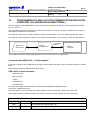
The PBX system ASB 150 02 can be connected to peripheral equipment via asynchronous V.24 ports.
Local communication with peripheral computers or printers can take place on a V.24 port placed on the CPU-D_,
and AUX-board.
The boards CPU-D_ (ROF 157 518/_) and AUX_ (ROF 157 5119/_) have three V.24 ports each and the boards CPUD (ROF 157 518/1) and AUX (ROF 157 5119/1) have one V.24 port each.
The V.24 port 0 on the CPU-D_ board shall foremost be reserved for configuration and maintenance of the PBX.
A Hayes compatible modem for dialled up long distance communication can be connected to those V.24 ports.
By programming in ASB 150 02 the V.24 or RS-482 ports can be used for the following applications.
•
Printout of telephone directory
•
Output of call records CIL (Call Information Logging)
•
Activation and registration of facilities for hotel applications
•
Activation and registration of facilities for ACD (Automatic Call Distribution) applications
•
Input and output of data for configuration and maintenance of the PBX
External equipment that is to be connected must comply with the requirements of the protocols and formats
described in document INTERWORK DESCRIPTION (1-9/155 19-1/ASB 150 02 Uen).
1.1
Supplementary documents
Facility descriptions:
•
CIL (Call Information Logging)
140/155 34-ASB 150 Uen
•
Telephone directory
481/155 34-ASB 150 Uen
•
Hotel computer
241/155 34-ASB 150 Uen
Interwork description
1.2
1-9/155 19-1/ASB 150 02 Uen
Product numbers
CALLCENTRE SUPERVISOR
Standard
EN/ FAS BS 102 001/xxS
Basic
EN/ FAS BS 102 001/xxB
RASC, FAS 102 203
EN/LZB 103 1197
START OF OPERATION
Uppgjord/Prepared
Faktaansvarig - Subject responsible
3(17)
Dokumentnr/Documentnr
2/1537-ASB 150 02 Uen
Dokansv/Godkänd - Doc respons/Approved
2
Kontr/Checked
Datum/Date
Rev
99-07-15
H
Tillhör/Referens-File/Reference
INSTALLATION
The boards have filters built in for suppression of electromagnetic interference (EMI). But if the suppression shall be
in accordance with the stipulations for CISPR 22 class B, other types of cables for connection of peripheral equipment,
mentioned later on in this document, have to be used.
The specification for V.24 allows a distance of 15m. For longer distances it is recommended to install short haul
modems.
The peripheral units can be connected to the PBX via one of the following cables:
•
Connection of printer
TSR 902 0476/1 (length: 5 meters)
•
Connection of computer TSR 902 0448/1 (length: 5 meters))
•
Connection of modem
TSR 902 0466/1(length: 5 meters)
Equipment connected to the RS-485 port can have a range up to 1200m.
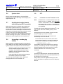
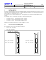
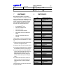
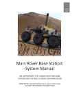
2.1
Pin connectors for V.24 I/O-ports
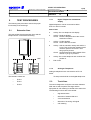
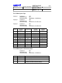
Pin connectors for V.24 I/O-ports in the PBX exist on boards:
•
CPU-D_ (ROF 157 5118/n)
•
AUX_ (ROF 157 5119/n)
FRONT OF BOARDS:
red
led
cld
start
CPU-D_ (ROF 157 5118/_)
AUX2
V.24
port
0
CPU-D (ROF 157 5118/1)
AUX
(ROF 157 5119/2)
(ROF 157 5119/1)
V.24
port
1
V.24
port
2
V.24
port
0
START OF OPERATION
Uppgjord/Prepared
Faktaansvarig - Subject responsible
4(17)
Dokumentnr/Documentnr
2/1537-ASB 150 02 Uen
Dokansv/Godkänd - Doc respons/Approved
3
Kontr/Checked
Datum/Date
Rev
99-07-15
H
Tillhör/Referens-File/Reference
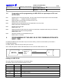
COMMANDS FOR PROGRAMMING OF ASB 150 02 FOR PERIPHERAL
COMMUNICATION
Command groups 60 and 64 are the groups used for programming of the external communication.
The command groups consist of commands defining parameters for external communication to/from ASB 150 02 via
V.24 ports.
Command groups
60xx is used for V.24 ports.
64xx is used for input/output of CIL and Hotel data.
3.1
Command overview, local connection via V.24 ports
6006
Pre-defined setting of the following functions in the V.24 port:
When the default is set = 3, the preprogrammed values below are set. These values match for a serial
printer.
Circuit 105-109
Parity
Echo
Stop bits
Word length
Line protocol
Control Characters
Not used
Not used
Not used
1
8
x-on, x-off
subvolume of PBX-internal
6007
Defines the character set to be used
Default value = 1, US-ASCII
6009
Defines the speed rate for the V.24 port
Default value = 14, 9600 bit/s
6010
Decides whether the PBX is master or slave when connected to certain types of locally connected
units. This command will be ignored when connecting certain types of external equipment see
command
6006 in the command manual.
Default value = 0 (master)
6011
Decides whether automatic selection of the port is allowed for temporary use of services which don't
have any port specified e.g. print out of telephone directory.
Default value = No, not allowed
6012
This command routes a connection request from the pheripheral unit to the desired service in the PBX.
Default values:
For the boards CPU-D_ and AUX, all ports = 1.
START OF OPERATION
Uppgjord/Prepared
5(17)
Dokumentnr/Documentnr
Faktaansvarig - Subject responsible
2/1537-ASB 150 02 Uen
Dokansv/Godkänd - Doc respons/Approved
Kontr/Checked
Datum/Date
Rev
99-07-15
H
Tillhör/Referens-File/Reference
3.2
Commands used for programming of ASB 150 02 for input/output of CIL and
HOTEL DATA
6401
Specifies which V.24 port(s) (card No., port No.) shall be used for input/output of call and hotel data.
Default value = ∩∩∩∩∩ (empty). The port is switched off
6402
States whether communication channel is active or not.
Default value = NO. Not active
6403
Specifies which format shall be used. All applications use CIL2 Hotel.
Default value: MD110/standard format
6404
Number of lines per page.
Default value = 63
6405
States the time limit within which the output must have been completed, before the port will become
faultmarked and an alarm will be generated.
Default value = 70s
6406
Automatic activation of a faultmarked V.24 port.
Default value = 5 minutes
4
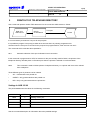
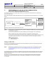
PROGRAMMING OF THE ASB 150 02 FOR COMMUNICATION WITH
RASC / CMG
As default the ASB 150 02 will use the V.24 port 0 on the CPU-D_ board as communication port to RASC /
Configuration Manager.
As default, RASC / CMG will use the COM1 port on the PC.
Use a cable with product number TSR 902 0448/1 for the connection ASB 150 02 ⇔ PC.
CPU-D_ or
AUX_
board
Data from
ASB 150 02
V.24-port
PC
Settings in ASB 150 02
The given values in the table below are the default values.
The default values match the default settings in RASC.
COMMAND
SETTING
FUNCTION
6006
03
Setting of V.24 port to match the communication RASC < > ASB 150 02
6007
1
Character set US-ASCII
6009
14
9600 Bit/s
6010
0
The PBX is master
6011
N
Not allowed for other services
6012
1
Operation and maintenance with RASC
START OF OPERATION
Uppgjord/Prepared
6(17)
Dokumentnr/Documentnr
Faktaansvarig - Subject responsible
2/1537-ASB 150 02 Uen
Dokansv/Godkänd - Doc respons/Approved
5
Kontr/Checked
Datum/Date
Rev
99-07-15
H
Tillhör/Referens-File/Reference
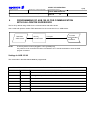
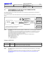
PRINTOUT OF TELEPHONE DIRECTORY
Use a cable with product number TSR 902 0476/1 for the connection ASB 150 02 ⇔ Printer.
CPU-D_
or AUX-board
Data from
ASB 150 02
V.24-port
Printer
It is not necessary to reserve a V.24 port for this purpose.
It is possible to program V.24 port(s) to allow other services than it is primarily programmed for.
At times when the V.24 port is not used for the purpose it is programmed for, other services can use it.
The command which make the above possible is:
6011
Automatic selection of this port is allowed in local connection
If this command is programmed to YES, for instance for the port normally used for RASC, the printout of the
telephone directory will take place on the same port when the printout is ordered via command 6502.
6502
This command is used to initiate printout of telephone directory on a printer and it has to be ordered
from a telephone
Three different types of printouts can be ordered:
•
ALL = All extensions are printed out
•
GUEST = Only guest extensions are printed out
•
DIR = Only non-guest extensions are printed out
Settings in ASB 150 02
The printer must match the values in the following commands
COMMAND
SETTING
FUNCTION
6006
x
Setting of V.24 port
6007
x
Character set
6009
x
Baudrate
6010
x
The PBX is master or slave
See the command description for information about the possible settings.
START OF OPERATION
Uppgjord/Prepared
Faktaansvarig - Subject responsible
7(17)
Dokumentnr/Documentnr
2/1537-ASB 150 02 Uen
Dokansv/Godkänd - Doc respons/Approved
6
Kontr/Checked
Datum/Date
Rev
99-07-15
H
Tillhör/Referens-File/Reference
PROGRAMMING OF ASB 150 02 FOR COMMUNICATION
WITH CALLCENTRE SUPERVISOR
The PC is by default using COM1 for the communication with ASB 150 02.
Use a cable with product number TSR 902 0448/1 for the connection PC ⇔ ASB 150 02.
Data from
ASB 150 02
NOTE:
CPU-D_
or AUX-board
PC with
CCS Standard
or
CCS Basic
V.24-port
A security device must be plugged in LPT1 (parallel port)
If a printer is to be connected it must be connected to LPT1 and be switched on when the ACD
program is started.
Settings in ASB 150 02
The commands in the table below must be programmed:
THIS SETTINGS FOR ASB 150 02 WILL MATCH THE DEFAULT SETTINGS IN THE ACD PROGRAM
COMMAND
SETTING
FUNCTION
3708
aabbb
6006
11
Setting of V.24 port to match the communication ACD ⇔ ASB 150 02
6007
0
The PBX internal set of characters
6009
8
1.200 Bit/s
6010
0
The PBX is master
6011
N
Automatic selection is not allowed
6012
2
ACD
aa = Card No., bb = port No. (starting from 0)
START OF OPERATION
Uppgjord/Prepared
Faktaansvarig - Subject responsible
8(17)
Dokumentnr/Documentnr
2/1537-ASB 150 02 Uen
Dokansv/Godkänd - Doc respons/Approved
7
Kontr/Checked
Datum/Date
Rev
99-07-15
H
Tillhör/Referens-File/Reference
PROGRAMMING OF ASB 150 02 FOR COMMUNICATION
WITH BUSINESSLINK FOR NOVELL
The BusinessLink for Windows NT Server PC is by default using COM1 for the communication with ASB 150 02.
Use a cable with product number TSR 902 0448/1 for the connection PC ⇔ ASB 150 02.
CTI Application
Server part
Data from
ASB 150 02
CPU-D_
or AUX-board
V.24-port
BusinessLink for
Windows NT
Server
Telephony Server
CTI Application
Client
Novell
Netware
Network
CSTA.dll
CTI Application
Client
CSTA.dll
NOTE:
For BusinessLink for Windows NT a FECU must be plugged into specific port on CPU-D_.
Settings in ASB 150 02
The commands in the table below must be programmed:
THIS SETTINGS FOR ASB 150 02 WILL MATCH THE DEFAULT SETTINGS IN THE ACD PROGRAM
COMMAND
SETTING
FUNCTION
8901
0000
Select CTI port (V.24)
3708
aabbb
aa = Card No., bb = port No. (starting from 0)
6007
1
US-ASCII set of characters
6009
14
9.600 Bit/s
6010
1
The PBX is slave
6011
N
Automatic selection is not allowed
6012
3
CTI
For a detailed instruction concerning the installation of the Server and the Client part please refer to the ‘Manager’s
Guide‘ of BusinessLink for Novell which is located in the BusinessPhone BusinessLink for Novell Binder (EN/LZB BS
103 014).
All activites on a customer server have to be carried out by a qualified and authorized network administrator.
Ericsson cannot be held responsible for failure, inoperability or unavailability of the server nor for hardware
incompatibility.
START OF OPERATION
Uppgjord/Prepared
Faktaansvarig - Subject responsible
9(17)
Dokumentnr/Documentnr
2/1537-ASB 150 02 Uen
Dokansv/Godkänd - Doc respons/Approved
8
Kontr/Checked
Datum/Date
Rev
99-07-15
H
Tillhör/Referens-File/Reference
PROGRAMMING OF ASB 150 02 FOR COMMUNICATION
WITH BUSINESSLINK FOR WINDOWS NT
The BusinessLink for Windows NT Server PC is by default using COM1 for the communication with ASB 150 02.
Use a cable with product number TSR 902 0448/1 for the connection PC ⇔ ASB 150 02.
CTI Application
Server part
Data from
ASB 150 02
CPU-D_
or AUX-board
V.24-port
BusinessLink for
Windows NT
Server
Telephony Server
CTI Application
Client
Microsoft
Windows
NT Network
CSTA.dll
CTI Application
Client
CSTA.dll
NOTE:
For BusinessLink for Windows NT a FECU must be plugged into specific port on CPU-D_.
Settings in ASB 150 02
The commands in the table below must be programmed:
THIS SETTINGS FOR ASB 150 02 WILL MATCH THE DEFAULT SETTINGS IN THE ACD PROGRAM
COMMAND
SETTING
FUNCTION
3708
aabbb
6006
11
Setting of V.24 port to match the communication ACD ⇔ ASB 150 02
6007
1
US-ASCII set of characters
6009
16
19.200 Bit/s
6010
1
The PBX is slave
6011
N
Automatic selection is not allowed
6012
3
CTI
6013
0
Dial attempts
aa = Card No., bb = port No. (starting from 0)
For a detailed instruction concerning the installation of the Server and the Client part please refer to the ‘Manager’s
Guide‘ of BusinessLink for Windows NT which is located on the BusinessPhone BusinessLink for Windows NT
product CD-ROM (EN/LZY BS 102 202/CD).
All activites on a customer server have to be carried out by a qualified and authorized network administrator.
Ericsson cannot be held responsible for failure, inoperability or unavailability of the server nor for hardware
incompatibility.
START OF OPERATION
Uppgjord/Prepared
Faktaansvarig - Subject responsible
10(17)
Dokumentnr/Documentnr
2/1537-ASB 150 02 Uen
Dokansv/Godkänd - Doc respons/Approved
9
Kontr/Checked
Datum/Date
Rev
99-07-15
H
Tillhör/Referens-File/Reference
PROGRAMMING OF ASB 150 02 FOR COMMUNICATION
WITH CALLCENTRE ASSISTANT (CCA)
The Telephony Server PC is by default using COM1 for the communication (via BusinessLink for Windows NT
Server) with ASB 150 02.
Use a cable with product number TSR 902 0448/1 for the connection BusinessLink for Windows NT - PC ⇔ ASB
150 02.
CCA Client
Call Centre
Assistant
Server
Data from
ASB 150 02
CPU-D_4
V.24-port
BusinessLink for
Windows NT
Server
CSTA.dll
Microsoft
Windows
NT Network
CCA Client
CSTA.dll
Telephony Server
CSTA.dll = BusinessLink for Windows NT 32-bit client
NOTE:
For BusinessLink for Windows NT a FECU (minimum Package 6: KDUBS 103 0x / 6) must be plugged
to specific port on CPU-D_4.
For Call Centre Assistant a security device (WIBU-key) must be plugged in LPT1 (parallel port)
Before installing Call Centre Assistant, BusinessLink for Windows NT software (Server
and Client part) and BusinessPhone software licensing (WIBU-key) must be installed.If a printer is to be
connected it must be connected to LPT1 and be switched on when the ACD program is started.
FECU: KDUBS 103 0x / 6
x = 6 (ASB 150 02 R9, R10)
x = 7 (ASB 150 02 R11)
Settings in ASB 150 02
No specific commands must be programmed for Call Centre Assistant. For specific ACD programmings see the
corresponging ACD Facility descriptions.
NOTE:
BusinessLink for Windows NT requires some settings in the ASB 150 02. For detailed information
see PROGRAMMING OF ASB 150 02 FOR COMMUNICATION WITH BUSINESSLINK FOR
WINDOWS NT
For a detailed instruction concerning the installation of the Server and the Client part please refer to the ‘Technical
Guide‘ of Call Centre Assistant which is located on the BusinessPhone Call Centre Assistant product CD-ROM
(FAS BS 102 204/CD).
All activites on a customer server have to be carried out by a qualified and authorized network administrator.
Ericsson cannot be held responsible for failure, inoperability or unavailability of the server nor for hardware
incompatibility.
START OF OPERATION
Uppgjord/Prepared
Faktaansvarig - Subject responsible
11(17)
Dokumentnr/Documentnr
2/1537-ASB 150 02 Uen
Dokansv/Godkänd - Doc respons/Approved
10
Kontr/Checked
Datum/Date
Rev
99-07-15
H
Tillhör/Referens-File/Reference
PROGRAMMING OF ASB 150 02 FOR COMMUNICATION
WITH OPERATOR SUITE (OPS)
The Telephony Server PC is by default using COM1 for the communication (via BusinessLink for Windows NT
Server) with ASB 150 02.
Use a cable with product number TSR 902 0448/1 for the connection BusinessLink for Windows NT - PC ⇔ ASB
150 02.
OWS Client
SQL
database
Data from
ASB 150 02
CPU-D_4
V.24-port
Operator Suite
Server *)
(DNA Server)
BusinessLink for
Windows NT
Server
CSTA.dll
Microsoft
Windows
NT LAN
OWS Client
DMG Client
CSTA.dll
Telephony Server
DMG Client
*) It is possible to install BusinessLink for Windows NT (server and client) and
Operator Suite (server and client) on the same machine.
CSTA.dll
CSTA.dll = BusinessLink for Windows NT 32-bit client
NOTE:
For Operator Suite a FECU (minimum Package 1: KDUBS 103 0x / 1) must be plugged to specific port
on CPU-D_4.
For Operator Suite a security device (WIBU-key) must be plugged in LPT1 (parallel port). Security
device (WIBU-key) requires the installation of specific software. The security device software is
automatically installed by the default OPS installation.
Before installing Operator Suite, BusinessLink for Windows NT software (Server
and Client part) must be installed.
FECU: KDUBS 103 0x / 1
x = 6 (ASB 150 02 R9, R10)
x = 7 (ASB 150 02 R11)
Settings in ASB 150 02
COMMAND
SETTING
0175
Y
NOTE:
FUNCTION
Use as CTI operator instrument? Command must be set to Yes for each
extension used as CTI operator (free seating).
For specific Operator programmings see the corresponding Facility descriptions (e.g. Voice Paging,
Night Mode, ...).
BusinessLink for Windows NT requires some settings in the ASB 150 02. For detailed information
see PROGRAMMING OF ASB 150 02 FOR COMMUNICATION WITH BUSINESSLINK FOR
WINDOWS NT
START OF OPERATION
Uppgjord/Prepared
Faktaansvarig - Subject responsible
12(17)
Dokumentnr/Documentnr
2/1537-ASB 150 02 Uen
Dokansv/Godkänd - Doc respons/Approved
Kontr/Checked
Datum/Date
Rev
99-07-15
H
Tillhör/Referens-File/Reference
For a detailed instruction concerning the installation of the Server and the Client part please refer to the ‘Technical
Guide‘ of Operator Suite which is located on the BusinessPhone Operator Suite product CD-ROM
(FAS BS 102 205/CD).
All activites on a customer server have to be carried out by a qualified and authorized network administrator.
Ericsson cannot be held responsible for failure, inoperability or unavailability of the server nor for hardware
incompatibility.
11
GENERAL INFORMATION FOR CIL WITH ASB 150 02
Two V.24 ports in ASB 150 02 can be programmed for communication with a hotel computer and/or equipment for
processing of CIL-data.
If the PBX is to be connected to a hotel computer, both V.24-ports or the bi-directional must be used for that
communication.
If the PBX is to be connected to equipment for processing of call information logging, one V.24-port is needed. The
other V.24 port can be programmed so it sends out the same information, (by programming that port with the same
commands as the ordinary port).
The setting of the two ports with the commands for programming of the V.24-ports may be different.
The setting of the commands for the V.24-ports must match the setting of the V.24-ports in the external equipment to
which they are connected.
Formats
The table below shows the differences between the two formats which can be used for CIL.
For complete description of the formats, see document INTERWORK DESCRIPTION (1-9/155 19-ASB 150 02 Uen
FORMAT
MD110/
standard
CILHOTEL
CIL2HOTEL
FUNCTION
Queue time
Date
Directory No. -Trunk
Sequence number
Message code
Queue time
Date
Directory No. -Trunk
Sequence number
Message code
Dialled access code
Information status I
Costs
Sent access code
Sent number
DESCRIPTION
Minutes
Month, day
0-9999
Not included
Not included
Minutes, seconds
Year, month, day
Not included
001-999
2 characters
0-9999
outgoing,
incoming,internal
11 digits
0-9999
1-20 digits
START OF OPERATION
Uppgjord/Prepared
Faktaansvarig - Subject responsible
13(17)
Dokumentnr/Documentnr
2/1537-ASB 150 02 Uen
Dokansv/Godkänd - Doc respons/Approved
Kontr/Checked
Datum/Date
Rev
99-07-15
H
Tillhör/Referens-File/Reference
ORA (On-line Ringtime Analyser)
This is a facility in CAM. If it is to be used, it is advisable that command 6403 have the setting stated below.
Otherwise the ringtime will be shown as minutes instead of seconds.
ASB 150 02
Command 6403 = 7
12
PROGRAMMING OF ASB 150 02 FOR COMMUNICATION
The V.24 port which is used must be set active with command 6402.
Data from
ASB 150 02
CPU-D_
or AUX-board
V.24-port
active
External equipment
for processing of
CIL information.
Use a cable with product number TSR 902 0448/1 for the connection PC ⇔ ASB 150 02.
NOTE:
A security device must be placed in LPT1 (parallel port) if CAM is used.
Settings in ASB 150 02
The commands in the table below must be programmed.
THIS SETTINGS WILL MATCH THE DEFAULT SETTINGS IN CAM
COMMAND
SETTING
FUNCTION
6201
x
Log internal calls. This command must be set to yes if internal calls shall be
logged. Default value = No
6202
x
Logging of incoming external calls. Default value = No
6301
x
Log outgoing calls. This command must be set to yes for those trunks which
shall be logged. Default value = No
6006
10 or 5,6
6007
3 or 1
6009
8
1200 Bit/s
6010
0
The PBX is master
6011
N
Not allowed for other services
6401
aabbb
6402
Yes
6403
CIL2HOTEL
Setting of V.24 port to match the communication with ASB 150 02
Character set to match Softech PC-program
aa = Card No, bb = port No. (starting from 0)
Activation of V.24 port
Format to be used to match Softech’s PC-program
(rem: CIL2HOTEL only required in conjunction with ISDN, Least Cost Routing
or if costs instead of pulses should be presented
START OF OPERATION
Uppgjord/Prepared
Faktaansvarig - Subject responsible
14(17)
Dokumentnr/Documentnr
2/1537-ASB 150 02 Uen
Dokansv/Godkänd - Doc respons/Approved
13
Kontr/Checked
Datum/Date
Rev
99-07-15
H
Tillhör/Referens-File/Reference
PROGRAMMING OF ASB 150 02 FOR COMMUNICATION WITH HOTEL
COMPUTER
See also chapter 7, PROGRAMMING OF ASB 150 02 FOR COMMUNICATION WITH CALLCENTRE ASSISTANT
(CCA) on page 10.
This application needs two V.24 ports or one bi-directional, one for each direction. In the direction ASB 150 02 to
Hotel computer it will be sent information such as CIL data and guestroom status.
In the direction Hotel computer to ASB 150 02 it will be sent information such as check in, check out and wake up.
CPU-D_
or AUX-board
Data from
ASB 150 02
V.24-port 0
active
HOTEL
Computer
Data from
ASB 150 02
CPU-D_
or AUX-board
V.24-port 1
active
Use a cable with product number TSR 902 0448/1 for the connection PC ⇔ ASB 150 02.
V.24 PORT USED FOR COMMUNICATION FROM ASB 150 02 TO FDM
COMMAND
SETTING
FUNCTION
6201
x
Log internal calls. Default value = No
6202
x
Logging of incoming external calls. Default value = No
6301
x
Log outgoing calls. This command must be set to yes for those trunks which
shall be logged. Default value = No
6006
10
6007
x
Character set
6009
8
1200 Bit/s
6010
0
The PBX is master
6011
N
Automatic selection is not allowed
6401
aabbb
6402
Yes
6403
CILHOTEL
6405
70
I/O time supervision in seconds
6406
5
Auto I/O activation in minutes
Setting of V.24 port to match the communication FDM ⇔ ASB 150 02
aa = Card No, bb = port No. (starting from 0)
Activation of V.24 port
Format to be used to match Softech’s PC-program
START OF OPERATION
Uppgjord/Prepared
Faktaansvarig - Subject responsible
15(17)
Dokumentnr/Documentnr
2/1537-ASB 150 02 Uen
Dokansv/Godkänd - Doc respons/Approved
Kontr/Checked
Datum/Date
Rev
99-07-15
H
Tillhör/Referens-File/Reference
V.24 PORT USED FOR COMMUNICATION FROM FDM TO ASB 150 02
COMMAN
D
SETTING
FUNCTION
6006
10
6007
x
Character set
6009
8
1200 Bit/s
6010
1
The PBX is slave
6011
N
Automatic selection is not allowed
6401
aabbb
6402
Yes
6403
CILHOTEL (in)
6405
70
I/O time supervision in seconds
6406
5
Auto I/O activation in minutes
Setting of V.24 port to match the communication FDM ⇔ ASB 150 02
aa = Card No, bb = port No. (starting from 0)
Activation of V.24 port
Format to be used to match Softech PC-program
START OF OPERATION
Uppgjord/Prepared
Faktaansvarig - Subject responsible
16(17)
Dokumentnr/Documentnr
2/1537-ASB 150 02 Uen
Dokansv/Godkänd - Doc respons/Approved
14
Kontr/Checked
Datum/Date
Rev
99-07-15
H
Tillhör/Referens-File/Reference
PROGRAMMING OF ASB 150 02 FOR COMMUNICATION WITH HOTEL
COMPUTER (V.24 INTERFACE Bi-DIRECTIONAL)
See also chapter 7,PROGRAMMING OF ASB 150 02 FOR COMMUNICATION WITH CALLCENTRE ASSISTANT
(CCA) on page 10.
This application needs one V.24 ports, one port for both directions. This port can only be installed in an CIL-port 0.
Use RASC command 6401 and activate.
In the direction ASB 150 02 to Hotel computer it will be sent information such as CIL data and guestroom status.
In the direction Hotel computer to ASB 150 02 it will be sent information such as check in, check out and wake up.
CPU-D_
or AUX-board
Data from
ASB 150 02
V.24-port 0
active
HOTEL
Computer
Use a cable with product number TSR 902 0448/1 for the connection PC ⇔ ASB 150 02.
Communication ASB150 02 ⇔ Hotel computer
If the hotel computer is used, ASB 150 02 normally uses the following formats. They are programmed with command
6403.
The following formats are available for hotel functions:
ASB 150 02 to Hotel computer
ASB 150/ht (bi)
MD 110/ht (bi)
HIS(bi)
CILHOTEL(bi)
CIL2HOTEL(bi)
For further information about the formats, see document INTERWORK DESCRIPTION
(1-9/155 19-1/ASB 150 02 Uen).
The bi-directional V.24 for CIL Hotel can only be istalled on port 0 (cmd 6401). Activate port 0 with YES.
In this case the port 1 is used as backup. This means this port can not be used for any other application.
V.24 PORT USED FOR COMMUNICATION FROM ASB 150 02
COMMAND
SETTING
FUNCTION
6201
x
Log internal calls. Default value = No
6202
x
Logging of incoming external calls. Default value = No
START OF OPERATION
Uppgjord/Prepared
Faktaansvarig - Subject responsible
17(17)
Dokumentnr/Documentnr
2/1537-ASB 150 02 Uen
Dokansv/Godkänd - Doc respons/Approved
Kontr/Checked
Datum/Date
Rev
99-07-15
H
Tillhör/Referens-File/Reference
V.24 PORT USED FOR COMMUNICATION FROM ASB 150 02
COMMAND
SETTING
FUNCTION
6301
x
6006
13
6007
x
Character set
6009
x
Baudrate
6010
1
The PBX is slave
6011
N
Automatic selection is not allowed
6401
aabb
6402
Yes
6403
CIL2HOTEL(bi)
6405
70
I/O time supervision in seconds
6406
5
Auto I/O activation in minutes
Log outgoing calls. This command must be set to yes for those trunks which
shall be logged. Default value = No
Hotel computer, bi-directional V.24 (Type 4)
aa = Card No, bb = port No. (starting from 0)
Activation of V.24 port
Format for bi-directional V.24
START OF OPERATION
Prepared
SEA/EBMP Stangelberger AT/SEA/EBAU
Doc. respons/Approved
1(8)
Documentnumber
Subject responsible
3/1537-ASB 150 02 Uen
Kontr./Checked
SEA/EBMP
Date
Rev
Reference
1998-05-29
E
ASB 150 02
Database reference
3/1537-ASB 150 02Uen-1-E.fm
START OF OPERATION
PC OPERATOR V1.2
Contents
Page
1
GENERAL . . . . . . . . . . . . . . . . . . . . 2
2
UNPACKING . . . . . . . . . . . . . . . . . . 3
3
SUPPLEMENTARY DOCUMENTS . 3
4
SYSTEM REQUIREMENTS . . . . . . . 3
4.1
PC HW Requirements . . . . . . . . . . . 3
4.2
ASB 150 02 Requirements . . . . . . . . 4
4.3
Electrical Connections . . . . . . . . . . . 4
5
SW-INSTALLATION . . . . . . . . . . . . . 5
6
START OF OPERATION . . . . . . . . . 5
7
MAINTENANCE . . . . . . . . . . . . . . . . 6
8
FUNCTION KEYS . . . . . . . . . . . . . . 6
9
PC OPERATOR V1.2 MAIN SCREEN7
10
TECHNICAL DATA. . . . . . . . . . . . . . 8
10.1
Desktop Adapter (ZAT BS 505 120) . 8
START OF OPERATION
Prepared
2(8)
Documentnumber
Subject responsible
3/1537-ASB 150 02 Uen
Doc. respons/Approved
1
Kontr./Checked
Date
Rev
1998-05-29
E
Reference
GENERAL
PC OPERATOR V1.2 is a PC application that runs under MS-WINDOWS® and provides all functions of a PBX
operator console. People working with this application should be familiar with MS-WINDOWS®. Both the operator
telephone and the PC screen show the ongoing call situation. The PC screen displays the extension field, information
fields and action keys. The OPERATOR telephone DBC 3214 or DIALOG 2663 is connected by an extension line via
the Desktop Adapter to the ELU-D. The PC has to have two V.24 interfaces (COM ports). One interface for connection
to the CPU-D4 and one interface for connection to the Desktop Adapter. The handset of the OPERATOR and the
optional headset is used for voice communication.
The system consists of the following parts:
- PC OPERATOR V1.2 (FAS 102 207/xx) connected to the CPU-D4
- AUX3 (ROF 157 5119/3) for the second or third PC-OPERATOR
- an ELU-D (ROF 157 5116/1) or ELU-D3 (ROF 157 5130/_)
- Desktop Adapter (ZAT BS 505 120)
- Connection cables (TRS 902 0448/1, TRS 190 05/2000, TRS 984 05/0 and TRS 984 08/0)
.
PC OPI
A
S
B
TRS 190 05/2000 or
use enclosed cable
PBX
1
5
0
OPERATOR INSTRUMENT
DBC 214 or Dialog 2663
ELU-D_
TRS 902 0448/1 max. 15m
CPU-D4
0
2
This range can be extended using RS 485
TRS 984 05/0 or use
enclosed cable with
RJ12 connectors
TRS 984 05/0 or
TRS 984 08/0
Desktop Adapter
If the extension line length exceeds
800m on a 0,5mm cable connect the
DBC 2663 using the BML 356 046 to
feed the telephone.
use the first port for
theV.24 connector
Wall contact
NEF 181 01/1-6
Figure 1 Electrical connections for PC OPERATOR equipment
START OF OPERATION
Prepared
3(8)
Documentnumber
Subject responsible
3/1537-ASB 150 02 Uen
Doc. respons/Approved
2
Kontr./Checked
UNPACKING
Date
Rev
1998-05-29
E
Reference
4
SYSTEM REQUIREMENTS
Check the delivery note to make sure that everything
has been received and refer to section 1 to see that no
cables are missing.
4.1
PC HW Requirements
For further information refer to the
An IBM® PC or compatibles with a 486DX 66MHz
processor or higher with an installed operating system
PC OPERATOR V 1.2
such as: MS-WINDOWS 3.1®, MS-WINDOWS for
package FAS 102 207/__
(01 - English - standard international or
14 - German - for Austria)
containing:
Workgroups 3.11®, MS-WINDOWS 95® or MSWINDOWS NT4.0®
•
At least 16 MB memory RAM
•
A 3-button mouse compatible
with MS-WINDOWS®.
- the USER’S MANUAL
- the SW INSTALLATION GUIDE
•
- four 3.5" installation disks.
3
SUPPLEMENTARY
DOCUMENTS
2 free serial ports should be available that are
configured properly (IRQ-settings, Base I/O
address) to be used within the MS-WINDOWS®
environment to connect the CPU-D4 and the
Desktop Adapter.
•
A graphic subsystem, supported by
MS-WINDOWS®, capable of using one of the
following resolutions with 256 colours:
INSTALLATION INSTRUCTION TAU-D
(47/1531-APD 101 02)
640 x 480 pixels
800 x 600 pixels
1024 x 768 pixels
DESCRIPTION TAU D (1551-ZAT BS 505 120)
•
A 3.5" 1.44 MB floppy drive.
•
A sound card, compatible to an MS-WINDOWS®
MT interface
•
Free hard disk space of about 15 MB for the
PC OPERATOR program.
•
Additional disk space for the bitmap pictures, if
they are used in the directory books. The
requirement may differ depending on the number
of entries stored in the directory book. In general,
about 15 kB are required for one bitmap picture
in the stated resolutions.
•
Free disk space for the directory book that uses
at least 64 kBytes or multiples of this value
depending on the number of entries in the
directory book.
MICROSOFT, MS-DOS and MS-WINDOWS are registered trademarks of Microsoft Corporation.
IBM is a registered trademark of International Business Machine Corporation.
START OF OPERATION
Prepared
4(8)
Documentnumber
Subject responsible
3/1537-ASB 150 02 Uen
Doc. respons/Approved
4.2
Kontr./Checked
ASB 150 02 Requirements
To connect the PC to the ASB150 02 system the
following boards are required:
•
ELU-D or ELU-D3 (when using the DBC 3214)
•
CPU-D4. If more than one PC-OPERATOR is
used the equivalent additional number of AUX3
(ROF 157 5119/3) boards are needed
•
4.2.1
DIALOG DBC 3214 or DIALOG 2663
OPERATOR console.
Date
Rev
1998-05-29
E
4.2.2
Connectors on the Desktop Adapter:
OPERATOR Console (OPI)
DIALOG DBC 3214 or DIALOG 2663 OPERATOR
console is designed for use as an OPERATOR
telephone for ASB 150 02.
The OPI possesses:
•
5x40-character tiltable display on the DIALOG
DBC 3214 and 4x40-character tiltable display on
the DIALOG 2663
•
up to 71 programmable function keys on the
DIALOG DBC 3214 and 20 programmable
function keys on the DIALOG 2663, each with
one LED
•
18 fixed function keys with 15 LEDs on the
DIALOG DBC 3214 and 23 fixed function keys
with 8 LEDs on the DIALOG 2663
•
4 menu keys
•
handset with mute button or optional headset
•
tone ringer with adjustable volume and signal
characteristics.
Desktop Adapter (ZAT BS 505 120)
The Desktop Adapter is situated between the operator
telephone and the ELU-D_. The Desktop Adapter
converts the visual display information of the
OPERATOR telephone to an asynchronous data
protocol for the PC OPERATOR program.
Reference
- RS-232-C port for V.24-connection to a PC
- modular jack for telephone line from the ASB 150 02
Connectors:
- modular jack for the OPERATOR telephone.
- jack connection for an incoming line from ASB 150 02
A LED on the Desktop Adapter shows operation/fault
condition of the unit.
or the Desktop Adapter
- jack connection for a handset/headset cord
- in the handset, jack connection for the cord.
Supplementary documents:
- User’s Guide
EN/LZT BS 102 197
- Facility Description
155 34-ASB 150 02
4.3
Electrical Connections
•
Connect supplied V.24 cable between the
Desktop Adapter and the PC.
•
Connect V.24 cable (TRS 902 0448/1) between
the PC and the AUX3. The standard length of the
cables is 5m. The cables are available with
lenghts up to 15 meters.
•
Use TRS 984 05/0 with modular plugs on both
ends or TRS 984 08/0 furnished for a wall socket
to connect the OPERATOR and the Desktop
Adapter.
START OF OPERATION
Prepared
5(8)
Documentnumber
Subject responsible
3/1537-ASB 150 02 Uen
Doc. respons/Approved
5
Kontr./Checked
SW-INSTALLATION
Date
Rev
1998-05-29
E
6
Reference
START OF OPERATION
Start up the PC and run MS-WINDOWS®.
1. Make sure the electrical connections have been
done as shown in figure 1 on page 2.
a
Insert the installation disk in drive A, and start the
File Manager
b
Activate disk A:\ and execute setup.exe. Then
you are prompted for a couple of settings.
2. Start up the exchange if it has not been powered up
yet. As soon as the Desktop Adapter has started
up, the "state LED" lights.
c
Select target directory
d
Configure application:
•
Select COM ports to connect the Desktop
Adapter and the CPU-D4
•
Select:
•
PC OPERATOR V1.2
(basic installation)
•
PC OPERATOR V1.2 sound support
(if a sound card is installed)
•
PC OPERATOR V1.2 photos
(if you want pictures in the operator field)
•
Select the preferred language
•
Select start-up/pop-up/connect properties
•
Configure the info system according to
ASB15002 programming
e
PC OPERATOR files are transferred to the
appropriate directories.
f
Setup is now complete. To activate the changes
restart MS-WINDOWS®.
When starting PC OPERATOR for the first time an
internal and then an external telephone directory
will be created.
3. Start MS-WINDOWS® on the PC.
4. Depending on the configuration the PC OPERATOR
V1.2 application can start automatically and if the
busy lamp information was stored previously, it
starts by prompting
"RESTORE PREVIOUSLY
LAMP INFORMATION" ?.
SAVED
BUSY
Confirm if this data is to be loaded again.
The application is now ready for operation.
NOTE: Usually the middle mouse button is not
used in MS-WINDOWS® applications. Verify the
switch setting on the mouse. Change from 2 to
3-button mouse operation and try answering an
incoming call to the operator with the middle
mouse button. If this fails, the correct mouse
driver is not installed. Install a mouse driver
supporting 3-button operation.
START OF OPERATION
Prepared
6(8)
Documentnumber
Subject responsible
3/1537-ASB 150 02 Uen
Doc. respons/Approved
7
Kontr./Checked
MAINTENANCE
Most operational disturbances can be related to
communication problems or screen faults. If the fault
relates to the display of the PC OPERATOR V1.2, try
changing the screen resolution or select large or small
font size. If the fault does not disappear contact the
person responsible for operation of the PBX and
provide her or him with the information about:
•
the MS-WINDOWS® version
•
which screen resolution is used
•
which font size is used
•
which graphics adapter is installed
•
which software version of the ASB 15002 is
installed
•
which type of OPERATOR instrument is
connected.
If the fault relates to communication problems between
the exchange and the PC OPERATOR V1.2, continue
with:
1. Check if the exchange is operating properly and all
external units are supplied with power.
2. Verify proper cable connection according to figure 1.
3. If you suspect a communication error try connecting
the OPERATOR console directly to the exchange.
4. If this was successful reconnect the OPERATOR
console via the Desktop Adapter and power up the
Desktop Adapter (see section 5 par. 2). If the
Desktop Adapter was connected, unplug it for 5
seconds so that the device performs a complete
restart.
5. If the fault remains and the above units function
check the V.24 lines for communication and the
COM-settings and/or try replacing the Desktop
Adapter.
If the fault still exists, contact the person responsible
for operation of the PBX.
Date
Rev
1998-05-29
E
8
Reference
FUNCTION KEYS
KEY
OPERATOR FUNCTION
ESC
0...9
Cancels Setup mode
Digits 0...9
*
/
*
#
A...T, a...t
F1
F2
F3
F4
F5
F6
F7
F8
F9
F10
F11
F12
RETURN
shift-F1
shift-F2
shift-F3
INSERT
HOME
PG UP
DELETE
END, SPACE
PG DN
UP
LEFT
RIGHT
DOWN
+/-
Programmable keys A...T
F1
F2
F3
F4
SAVE
METER
INFO
MESSAGE
LOOP 1
LOOP 2
LOOP 3
MONITOR
ENTER
OFF-DUTY
NIGHTSWITCH
MENUE
NOTIFY
SERIAL
BYPASS
CLEAR LEFT
IDENTIFY
CLEAR RIGHT
TRANSFER
SPEECH LEFT
SPEECH RIGHT
CONFERENCE
VOLUME CONTROL
LOUDSPEAKING
(↵) ENTER
BACKSPACE
SHIFT
START OF OPERATION
Prepared
7(8)
Documentnumber
Subject responsible
3/1537-ASB 150 02 Uen
Doc. respons/Approved
9
Kontr./Checked
Date
Rev
1998-05-29
E
Reference
PC OPERATOR V1.2 MAIN SCREEN
EXIT button
ERICSSON
PC OPI
V 1.2
ERICSSON PC Operator V 1.2
ERICSSON
PCOPI
V 1.2
5.1.98
13:36
+19o
SETUP button
INTERNAL Telephone Directory
I
EXTERNAL Telephone Directory
E
Configuration
Off duty/
Night service
201
202
203
204
244
busy lamp field
I
E
Com. Ind.
0 0
1
2
3
M
1
4
7
*
2
5
8
0
left operator field
right operator field
3
6
9
#
?
Com. Ind.
0 0
1
2
3
M
QUEUE
METER
LOOP
1
2
3
4
5
6
7
8
9
*
0
#
KEY
PAD
NOTIFY
SERIAL
BYPASS
CONFERENCE
IDENTIFY
?
Figure 2 PC OPERATOR Main Screen
Application Tips
•
Click the KEY PAD with the right mouse button to expand the KEY PAD on the screen.
•
Set night service with the programmable function key "T" ("C" on DBC 214). Enable this function by
programming a name call with " * 8 # ".
•
A picture related to an individual extension should have a width of 85 pixels and a height of 110 pixels with 256
colours.
START OF OPERATION
Prepared
8(8)
Documentnumber
Subject responsible
3/1537-ASB 150 02 Uen
Doc. respons/Approved
Kontr./Checked
10
TECHNICAL DATA
10.1
Desktop Adapter
(ZAT BS 505 120)
DIMENSIONS
-Length
-Width
-Height
-Weight
-Power consumption
152 mm
75 mm
33 mm
0.8 kg
1W
V.24 DATA INTERFACE
-Data format
-Circuits used
-Data bits
-Start bits
-Stop bits
-Parity
-Bit rate
-Line length to OPI/TAU
Asynchronous
102,103 and 104
8
1
1
None
9600 bps
15 m
Use a short-haul modem to extend the range up to
600m.
ENVIRONMENT
-Temperature
-Humidity
0-40° C
10-90% RH
Date
Rev
1998-05-29
E
Reference