1
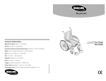
Invacare Zipper 2 Chair
R
INVACARE INTERNATIONAL
User Guide
Deutschland, Österreich, Switzerland & Eastern Europe: Kleiststraße 49 · D-32457 Porta Westfalica.
France: Route de St Roch (RD 36) · F-37230 Fondettes.
United Kingdom & Eire: South Road · Bridgend Industrial Estate · Bridgend CF31 3PY · UK
España: c/ Areny · s/n - Polígon Industrial de Celrà · E-17460 Celrà (Girona)
Portugal: Rua Senhora de Campanhã 105 · P-4369-001 Porto
Belgium & Luxemburg: Autobaan 14 · B-8210 Loppem
Danmark: Sdr. Ringvej 39 · DK-2605 Brøndby
Sverige & Suomi: Fagerstagatan 9 · P.O. Box 66 · S-163 91 Spånga
Nederland: Celsiusstraat 46 · NL-6716 BZ Ede
Italia:: Via dei Pini, 62 · I-36016 Thiene (VI).
Part No: QB99612 0605
Norge: Grensesvingen 9 · N-0603 Oslo
Introduction
You have just bought a manual wheelchair from our INVACARE range.
This model offers you all the advantages and characteristics of
a wheelchair that has been designed especially to meet your
par ticular requirements.
Great care has been taken with this wheelchair throughout the
whole of its manufacturing process. The components have been
selected for their quality and inspections have been carried out so
that your wheelchair can provide you with full satisfaction.
Note for wheelchair users
INVACARE provides a wide range of wheelchairs to meet the requirements
of users. However, the decision on the type of model to be prescribed rests
exclusively with qualified advisers.
INVACARE or its appointed representative shall not be held responsible if a
wheelchair is used that is unsuitable for the user’s level of disability, if the
wheelchair itself is incorrectly used or if a problem arises due to poor
maintenance.
The information set out in this manual may be modified without prior notice.
This manual contains copyright information. All rights are reserved. No part
of this document may be photocopied or reproduced without prior written
agreement from INVACARE or its appointed representative.
This manual gives details of all the options of the ZIPPER 2
range of wheelchairs. It describes the options, operation and
adjustments that may be required. However, your INVACARE
retailer will be able to give you further information and
demonstrations.
SAFETY NOTICE
PLEASE ENSURE THE WHEELCHAIR IS
FULLY OPENED AND THE SEAT RAILS ARE
LOCATED IN THE SEAT SADDLES BEFORE SITTING DOWN
1
Table of contents cont.
Table of contents
Page
Note for Wheelchair Users . . . . . . . . . . . . . . . . . . . . . . . . . . . . . . . .1
8. Folding chassis . . . . . . . . . . . . . . . . . . . . . . . . . . . . . . . . . .21
Table of contents . . . . . . . . . . . . . . . . . . . . . . . . . . . . . . . . . . . 2-3
9. Rear wheels . . . . . . . . . . . . . . . . . . . . . . . . . . . . . . . . . .21-22
1. Safety and operating limits . . . . . . . . . . . . . . . . . . . . . . . . 4-13
10. Castors . . . . . . . . . . . . . . . . . . . . . . . . . . . . . . . . . . . . . . . .23
1.1
Weight limit . . . . . . . . . . . . . . . . . . . . . . . . . . . . . . . . . . . . . 4
11. Brakes . . . . . . . . . . . . . . . . . . . . . . . . . . . . . . . . . . . . .23-24
1.2
Reaching for an object from a wheelchair . . . . . . . . . . . . . 4-6
12. Footrests . . . . . . . . . . . . . . . . . . . . . . . . . . . . . . . . . . . .24-26
1.3
Transferring to other seats . . . . . . . . . . . . . . . . . . . . . . . . . 7-8
13. Calf straps and heel loops . . . . . . . . . . . . . . . . . . . . . . . .26
1.4
Tilting the wheelchair. . . . . . . . . . . . . . . . . . . . . . . . . . . . 9-10
14. Backrest Extension . . . . . . . . . . . . . . . . . . . . . . . . . . . . . .27
1.5
Kerbs . . . . . . . . . . . . . . . . . . . . . . . . . . . . . . . . . . . . . . . . . 10
15. Rear Anti-tippers . . . . . . . . . . . . . . . . . . . . . . . . . . . . . . . .28
1.6
Stairs . . . . . . . . . . . . . . . . . . . . . . . . . . . . . . . . . . . . . . . . . 11
16. Transit version . . . . . . . . . . . . . . . . . . . . . . . . . . . . . . . . . .28
1.7
Upward and downward slopes . . . . . . . . . . . . . . . . . . . . 12-13
17. Amputee kit . . . . . . . . . . . . . . . . . . . . . . . . . . . . . . . . . . . .29
2. Use . . . . . . . . . . . . . . . . . . . . . . . . . . . . . . . . . . . . . . . . . . 13-14
18. Trays . . . . . . . . . . . . . . . . . . . . . . . . . . . . . . . . . . . . . . . . . .29
2.1
Folding and unfolding the wheelchair . . . . . . . . . . . . . . . 13-14
19. Safety belt . . . . . . . . . . . . . . . . . . . . . . . . . . . . . . . . . . . . .29
2.2
Propelling the wheelchair . . . . . . . . . . . . . . . . . . . . . . . . . . 14
20. Spoke guards . . . . . . . . . . . . . . . . . . . . . . . . . . . . . . . . . . .29
3. Summary of safety instructions . . . . . . . . . . . . . . . . . . . . . . 15
21. Tipping Lever . . . . . . . . . . . . . . . . . . . . . . . . . . . . . . . . . . .30
4. General description . . . . . . . . . . . . . . . . . . . . . . . . . . . . . 16-17
22. Routine checks and maintenance . . . . . . . . . . . . . . . .31-32
5. Backrests . . . . . . . . . . . . . . . . . . . . . . . . . . . . . . . . . . . . . . . . 18
23. Transport . . . . . . . . . . . . . . . . . . . . . . . . . . . . . . . . . . . .32-33
6. Seat . . . . . . . . . . . . . . . . . . . . . . . . . . . . . . . . . . . . . . . . . . . . 18
24. Guarantee . . . . . . . . . . . . . . . . . . . . . . . . . . . . . . . . . . . . . .34
7. The various types of armrest . . . . . . . . . . . . . . . . . . . . . . 19-20
25. Storage . . . . . . . . . . . . . . . . . . . . . . . . . . . . . . . . . . . . . . . .34
26. Cleaning . . . . . . . . . . . . . . . . . . . . . . . . . . . . . . . . . . . . . . .34
2
3
1-Safety and operating limits
2
Stability and equilibrium
To ensure that the wheelchair remains stable and is manipulated correctly, you
must always maintain good equilibrium. Many actions cause the user of a
wheelchair to reach out, lean over or move about within the wheelchair and
outside it. These actions will change your centre of gravity and weight
distribution of the wheelchair.
Your wheelchair has been designed to remain stable for normal everyday use
if it is used correctly taking the precautions recommended in this manual.
Position the castors to give the longest
possible wheel-base (Figure 2).
Lock the manual brakes on the rear wheels.
Leaning forwards
1.1 - Weight limit
(Figures 3, 4 and 5):
The maximum user weight limit for S & T models is 115kg and 100kg for
the SL & TL models.
This weight includes accessories such as a compact oxygen cylinder or other
equipment required by the user.
However, the wheelchair user's degree of activity is important. For example, an
active user weighing 75 kg may subject the wheelchair to more stress than a
user weighing 115 kg. We recommend very active wheelchair users to choose
an appropriate design of wheelchair. Your INVACARE approved distributor will
advise you on the best model.
1.2 - Reaching for an object
from a wheelchair
4
The limitations on reaching out from
a wheelchair shown in figure 1 have
been
produced
using
a
representative sample of wheelchair
users.
Only the ar ms should extend
beyond the seat of the wheelchair.
For safety reasons, the body and
head should remain within the
wheelbase.
3
Move the wheelchair as close as
possible to the object you wish to reach.
Only reach out to take what is within
arm's length in normal sitting position.
1
4
5
5
Leaning backwards
1.3 - Transferring to other
seats
9
(Figures 6 and 7)
Move the wheelchair as close as possible to object you wish to reach.
Only lean back for objects that are within arm's length in normal sitting
position.
6
7
It is possible to move from and to a
manually propelled chair if the
following guidelines are followed.
INVACARE does not recommend
any
par ticular
method
for
transferring:
This
is
the
responsibility of a medical adviser
who should consider your level of
disability and type of wheelchair .
10
When transferring, either to get out of
or return to your wheelchair, make
sure:
That the gap between the two seats is
as small as possible. (Figures 9 and 10)
Leaning to one side
(Figure 8)
8
This is the most dangerous manoeuvre as it is
easy to tip sideways.
To move up to the object and lean over, you must
use the castors as a means of keeping the
wheelchair stable and balanced. (Figure 2)
For your safety, it is essential to be in the
correct position.
That the manual brakes on the rear
wheels are on to prevent the wheels
moving. (Figure 11)
11
12
Turn both castors towards the seat to
which you wish to move. Lift up the
footplates .
Do not stand on the footplates .
Do not try to pick something up from the floor if
this would upset your balance.
6
7
13
Tilting without help from a third person
Wheelchairs in the INVACARE range have been designed for use by
those who have mastered the technique of balancing on the rear wheels
without help from a third person. However, you should never exceed the
limitations of the wheelchair. Repeated shock on the castors caused by
tipping the wheelchair up yourself may affect the rigidity or settings of
your wheelchair. If your wheelchair is fitted with accessories, these may
affect the methods used for balancing on the rear wheels.
When you wish to learn a new technique, consult an experienced person
for advice in using your type of wheelchair.
If possible, fold back the footrest
supports to the side to clear the
passage. (Figure 13)
14
If possible, remove the armrests on the
side between the wheelchair and the
other seat (Figure 14).
15
NB
Never stand up on the footplates.
(Figure 15).
8
1.4 - Tilting (balancing on the rear wheels)
Tilting with assistance from a third person:
The user should be sitting correctly and firmly in the chair or if unable to
support themselves, should be strapped in position to prevent him falling
out of the chair.
If a wheelchair user needs assistance in tilting the chair, the assistant must
know how to use his body correctly. Keep your back straight and bend at
the knee to tilt the wheelchair. Never exert too much force. The medical
team in charge of the user will advise you in the methods best suited to
your morphology. The INVACARE approved distibutor will provide you with
information on the risks of using the wheelchair incorrectly if the wheelchair
has removeable parts such as armrests or leg rests. These must NEVER
be used as aids when lifting as they may inadvertently become detached
and cause injury .
To tilt the wheelchair, a third person should grip the handles firmly. (Figure
16) Warn the user of the wheelchair
16
before tilting it and remind him/her to
lean backwards. Check that the user's
feet and hands are clear of all the
wheels. Place a foot on the foot step
tube and push smoothly until the
wheelchair is at the point of equilibrium.
At this stage, the helper will feel a
differ-ence in weight distribution which
usually occurs at an angle of about 30°.
Turn the wheelchair in the direction
required and negotiate the obstacle.
9
Lower the front of the wheelchair smoothly, holding the handles firmly. Use your
weight on the foot step tube to act as a counterweight. Do not lower the wheelchair
suddenly for the last few centimetres before returning to the normal position. This
might hurt the user.
1.5 - Kerbs or obstacles 30 to 50 mm high
17
10
Make sure that you get hold of
fixed, non-removable par ts only.
Use the following procedure for
going up stairs. (Figure 19):
Tilt the wheelchair to its point of
equilibrium. One helper (at the
back) holds the wheelchair up
against the first step, gripping the
handles firmly to lift.
19
The second helper, holding firmly a fixed part of the front frame, lifts
the wheelchair above the stairs and holds it while the first helper
places one foot on the following step and repeats the operation.
Method 2
(Figure 18)
The helper should stand on the pavement
and turn the wheelchair until the rear
wheels are against the kerb. Tilt the
wheelchair backwards to the point of
equilibrium and, in a continuous
movement, pull the wheelchair until the
rear wheels mount the kerb and pass
onto the pavement. Do not lower the
castors to the ground until you have
pulled the backrest of the wheelchair
sufficiently far to clear the kerb.
NB: Folding backs should always be
checked to ensure they are engaged.
We recommend that you take very great care when taking a wheelchair up
or down stairs. Two people are required for this.
ADVICE TO THIRD PERSONS
Method 1 - Negotiating the obstacle forwards
(Figure 17)
The helper should tilt the wheelchair
until the castors have passed over
the kerb. Move the wheelchair
forwards and lower the castors
gently onto the pavement. Push the
wheelchair until the rear wheels
touch the kerb. Lift and push until the
rear wheels have mounted the kerb.
Do not just lift by the handles on the
backrest.
1.6 - Steps, stairs or obstacles over 50 mm high
The wheelchair must not be lowered until the last step has been
negotiated and until the chair is clear of the stairs.
18
Escalators
Do not use an escalator when moving a wheelchair from one floor to another.
This might cause serious injury.
11
1.7 - Upward and downward slopes (operating limits)
Do not attempt to go up or down
slopes greater than 9% without
assistance. (Figure 20)
20
Downward slopes
23
Lean backwards carefully and allow the
handrims to slide through your hands.
Be ready to react at any moment to
check the speed and direction by
keeping in close contact with the
handrims. The manual brakes should
not be used to slow you down. (Figure
23)
If you are going up or down a slope
avoid turning sharply and never try to
go up or down diagonally.
2-Use
Always go straight up and down
slopes otherwise the wheelchair
might overturn. (Figure 21)
21
2.1 - Folding and unfolding the wheelchair
Wheelchair with fabric upholstery.
To fold
Lift the footplates .
Release the backrest tensioner if necessary.
Using both hands, take the centre of the seat fabric at the front and back
edges and raise it. (Figure 24).
Or, tilt the wheelchair to one side and close it using the handles on the back
rest or the armrests. (Figure 25).
Upward slopes
Lean the upper part of the body
forward and push the chair forward with
short quick thrusts on the handrims to
maintain speed and control direction. If
you wish to take a rest, apply both
brakes when stopping. (Figure 22).
22
24
25
NB: The use of Anti Tippers is
recommended in traversing of upward
slopes.
12
13
To unfold
(Figure 26)
26
of instructions for use for improved safety
- User weight limit (including accessories): 115kg for an adult wheelchair, 50 kg
for a child’s wheelchair
- Do not try to reach objects if you have to move forward on the seat
- Do not try to reach objects on the ground if you have to lean down beyond
the safety limits
- Do not lean too far back to reach objects behind you: you may tip over.
- Do not move your weight, or your sitting position in the direction in which you
wish to go: you may tip over.
- Always apply both manual brakes before trying to get out of or back into the
wheelchair.
- The manual brakes are not designed for slowing you down.
- Do not try to stop a moving wheelchair using the manual brakes.
- Do not tilt the wheelchair without assistance from a third person when
negotiating obstacles more than 30 mm high
- Do not use an escalator for moving a wheelchair from one floor to another.
(This may cause serious injury.)
- Do not use your wheelchair if the tyres are not inflated to the correct
pressure shown on the side.
- Do not over-inflate the tyres. Failure to comply with these instructions may
cause the tyre to burst and cause bodily injury.
- Carry out the regular checks recommended in this guide and by your
INVACARE approved retailer.
- Use your wheelchair with respect for other people
- Do not use your wheelchair as a transport seat in a vehicle. Unless it is not
practical for the userto be transferred (Refer to section 23 - Transport).
Unfold the wheelchair by taking hold
of the armrest or the side of the
chair nearest to you, tip the chair
sideways (lifting the rear wheel and
the caster from the ground) and
press on the tube supporting the
seat upholstery until it is fully down.
The seat upholstery should be fully
open .
NB
Ensure that the seat rails are fully engaged in the plastic carriers
before sitting down.
To avoid injury, keep hands and fingers away from moving parts
(armrests, folding frame, footrest supports or leg rests, etc).
2.2 - Propelling the wheelchair
The wheels of your wheelchair are fitted with handrims. (Figure 27)
The qualified personnel will be able to advise you on the most
appropriate way of propelling yourself.
Various accessories may be fitted to
improve the grip (plastic coatings,
studs).
3. Summary
27
Lean the upper part of the body
forward and push the chair forward
with short quick thrusts on the
handrims to maintain speed and
control direction.
Be ready to react at any moment to
check the speed and direction by
14
15
4. Description
Each wheelchair is specially designed to meet the requirements
of its user. This manual describes how to adjust the chairs in this
range, enabling you to find out how to adjust the wheelchair to
suit your needs.
Backrest
Armrest
General description
Your wheelchair has a number of main parts which will be
mentioned throughout this manual.
These parts are described below.
Support is provided by the backrest, seat and armrests.
The folding chassis comprises of the side frames and folding
cross brace.
This is the essential supporting framework of the wheelchair on
which all the other parts are mounted.
Handrim
Seat
The rear wheel comprises of the wheel, axle and handrim.
The rear wheels provide contact with the ground and are driven by
turning the handrims.
The front castors comprise of the fork and wheels.
The front wheels provide contact with the ground and the rotating forks
steer the chair.
Manual brake
The manual brake is used to park the wheelchair.
Swing away footrest support and leg rest
These are connected to the chassis and can be swung away to make
transfer easier to and from the wheelchair.
The footplate assembly comprises of the adjustable tube and foot
plate. These support your feet.
The heel support strap or calf support strap
These two straps support your feet or legs in the best position.
These parts are illustrated on the following diagram.
Rear
Wheel
16
Manual
Brake
Front
Castor
Swingaway
Footrest
Support
Footplate
17
5. Backrest
7. The various types of armrest
Photographs 1 and 2
The backrest can be folded at the middle by means of a locking
mechanism and can be operated by either the user or an
attendant.
-Use: To fold the backrest, pull both black plastic locking levers (A)
downwards and fold the top part of the backrest to the back and then
down. Carry out these operations in the reverse order to return the
backrest to its normal position, making sure that the locking
mechanisms (A) are secure.
1
2
Photograph 4 & 5
The arm rest has a tube which supports the front and back locking
devices as well as the armrest pad. This armrest can be swung
towards the back, and can also be removed if required.
Removal: Turn the front lock (A) and the back lock
(B) in order to release.
Lift up the armrest. Carry out this operation in
reverse order to replace the armrest. Turn the front
lock (A) and lock (B) in order to firmly secure the
armrest to its locations.
6. Seat
6.1 Seat
Photograph 3
- Your seat upholstery is screwed onto the seat tubes of the folding
cross brace.
3
A
4
A
5
B
A
- Adjustment: This model does not require any
adjustment.
Full length swingaway and removable armrest
Photographs 6
The arm rest has a tube which supports the front and back locking
devices as well as the armrest pad. This armrest can be swung
towards the back, and can also be removed if required.
B
6.2 Seat cushion
The seat cushion is placed on the upholstery and must be removed
when folding the chair.
18
Removable, swingaway desk armrest
- Use:
To swing away, turn the front lock (A) in order to
release. Lift the armrest and position it towards
the back in order to carry out lateral transfers.
Carry out these operations in reverse order to
replace the armrest. Turn the front lock (A) in
order to firmly secure the armrest to its location.
A
- Adjustment: This model requires no
adjustment. Just check regularly that the screws
(A) are tight. If the washers (B) are loose, these
screws should be tightened. If the problem
continues, contact your INVACARE retailer and
ask him to change the mounting for safety
reasons.
The armrests are fitted in pairs on the wheelchair. When removing
them, remember that there is one armrest for the right hand side
and another for the left hand side.
- Use:
To swing away, turn the front lock (A) in order to release. Lift the
armrest and position it towards the back in order to carry out lateral
transfers. Carry out these operations in reverse order to replace the
armrest. Turn the front lock (A) in order to firmly secure the armrest to
its location.
19
Removal: Turn the front lock (A) and the back lock (B)
in order to remove the armrest.
Lift up the armrest. Carry out this operation in
reverse order to replace the armrest. Remember
that the curved part of the tube should be facing
forward. Turn the front lock (A) and the lock (B) in
order to firmly secure the armrest to its locations.
6
C
B
Side Frames
A
- The side frames provide the mounting points for the rear wheels
and the castors.
- Adjustment: No adjustment is possible on this series of wheelchair.
Note: The armrest is reversible so that slot C can be used to hold an NHS
tray.
Folding cross brace
- Adjustment: This model does not require any adjustment.
- The folding cross brace has two members which enable the
wheelchair to be folded.
Removable, swing away adjustable height armrest
Photographs 7 and 8
- The adjustable height armrest has a tube which supports the back
and front locks as well as the adjustable armpad tube. This armrest
can be swung towards the back and can be removed, if required.
7
B
A
Removal: Turn the front lock (A) and the back lock (B) in order to remove the
armrest.
Lift up the armrest. Carry out this operation in reverse order to replace the
armrest. Remember that the incurved part of the tube should be facing
forward. Turn the front lock (A) and the lock (B) in order to firmly secure the
armrest to its locations.
Height adjustment: Loosen the hand wheel
(D) and push in the button spring (E),
adjust to the desired height and tighten the
hand wheel (D). The hand wheel (D) can
be replaced by a screw (not included) for
users who do not often change the height
of the armrest.
- Adjustment: No adjustment is required. To fold or unfold your
wheelchair, refer to this user and safety manual.
9. Rear wheels
Wheels
- Use:
To swing away, turn the front lock (A) in
order to release. Lift the armrest and
position it towards the back in order to
carry out lateral transfers. Carry out these
operations in reverse order to replace the
armrest. Turn the front lock (A) in order to
firmly secure the armrest to its location.
20
8. Chassis
8
D
E
Photograph 9
- The rear wheels are positioned on rear wheel mounting blocks
which determine the rearward stability This position should only be
adjusted by a qualified technician on the advise
of the qualified advisor.
9
The rear wheels have a diameter of either 600
mm, 550 mm, or 500 mm. They are equipped
with spokes and handrims. They can have
pneumatic tyres or solid tyres and can be
connected to the side frame by means of a
fixed axle or a quick release axle.
Tyre pressure.
The pressure is shown on the tyre and must never be exceeded. The
maximum permitted pressure is 450 kPa (65 PSI - 4.5 bar).
Remember that the tyre pressure on both wheels should be the same
to ensure perfect steering.
In case of a puncture, the tyre has to be removed from the rim. Press
the valve to let all the remaining air out of the inner tube. Pull the tyre
off the rim. Repair or replace the inner tube. Put the tyre back on the
rim. Inflate the tyre to the required pressure.
21
10. Castors
- Note: It may be necessary to use one or two tyre removal tools (not
supplied).
Front wheels
- The front wheels have a diameter of either 190mm or 125 mm
available in solid puncture-proof tyres only.
No adjustment is necessary for the front wheels.
Warning
Applicable only to chairs fitted with 24" wheels.
These chairs are assembled with the wheels set in the rearward
position. It is important that the chairs are not re-configured with the
wheels set in the "forward" position; this would allow the footrest
hangers to disengage the brake levers when swung away from their
locked position, causing the chair to become unstable.
Forks
Photograph 12
- The fork connects the chassis and the wheel.
12
- Adjustment: The forks do not require
adjustment. Check that the fork rotates freely.
Handrims
- The handrims are used by the user to drive the wheelchair.
- NB: As the handrims are in contact with your hands, make sure that
they are not damaged and that the surface has no parts which might
cause injury to the hands.
11. Manual brakes
- Adjustment: No adjustment is required for the handrims.
Brakes
Axles
- The manual brakes are used to immobilise the wheelchair in a
stationary position. They are not intended for slowing down and should
not be used when the wheelchair is moving.
They should be applied together.
Photographs 10 and 11
- The axles link the back wheels to the chassis.
They are fixed or quick releasing.
Photograph 13
10
A
- Use: The brakes are operated by moving the
brake handle (A) towards the front of the
wheelchair. When the brakes are applied, the
wheelchair should resist movement.
- Quick release wheels
Removal: Push on the quick release button
head with your finger and pull the wheel
towards the outside of the chair.
- Assembly: Push on the quick release button
head with your finger and locate axle though the
axle bush, making sure that the axles are
secured (no axial movement).
- Fixed wheels.
No adjusment is required, however, check on a
weekly basis that the axle / nut are secure.
22
13
11
- Adjustment: It may be necessary to adjust the
brakes after repairing a puncture or because of wear on the pneumatic
or solid tyre. Slacken clamp screws and adjust the brake assembly to
achieve adequate braking. Tighten the clamp screws firmly after
adjustment.
- Note: The brakes are fitted in pairs to the wheelchair. When adjusting
or removing, remember that there is one brake for the right hand side
and another for the left hand side.
23
- Use: the operations for swing away and removing are the same
as for the footrest supports (10.1).
Brake extension
Photograph 14
- The brakes may be equipped with a handle
extension to assist attendants/user who have
insufficient strength or difficulty in reaching the
standard brake handles.
- Adjustment: To adjust the angle of the leg rest, lift it upwards to the
angle required. To lower the leg rest, hold the leg in one hand and
operate the release lever (A) with the other hand. Lower to the
required position.
12. Footrest
14
Swing away footrest supports
Photograph 15 and 16
The footrest supports can be swung away to the outside/rear of the
wheelchairs to free the front of the wheelchair and making it easier
for the user to transfer to another seat. They can be removed.
- Use: To swing the support to the outside, press the release
mechanism lever (A). Rotate the support carefully to the outside of
the wheelchair.
To return the support, repeat the operations in the reverse order.
Check that the release mechanism (A) has automatically locked.
To remove the support, carry out the same operation as for swing
back and lift the support upwards. To refit it, offer the support in the
open position, align the holes (B) on the pivots
(C) and press down. Rotate the support to the
locked position.
15
- Adjustment: The footrest supports cannot be
adjusted.
A
- Note: The footrest supports are fitted in
pairs to the wheelchair. When adjusting or
removing, remember that there is one support
for the right hand side and another for the left
hand side.
Elevating leg rests
Photographs 17 and 18
The leg rests shown are leg rest supports with
an integral pad for supporting the lower leg. The
leg rests can be swung away and removed.
24
16
B
C
The calf support pad can be pivoted when folding the wheelchair.
The position can also be set on the mounting tube in one of three
locations .It can also be set along the mounting
tube by sliding into the chosen location (18).
17
- NB: The elevating legrests are fitted in pairs to
the wheelchair. When adjusting or removing,
remember that there is one elevating legrest
for the right hand side and another for the left
hand side.
A
B
Footplate Assemblies
Independent footplates for footrest supports
Photograph 19
18
The footplate assemblies comprise of an
adjustment tube and footplate and are intended solely as a foot
support when you are sitting in the wheelchair and should not be
used for standing. The position of your feet can be retained by either
heel loops or a calf strap. Each footplate assembly can be adjusted
in height. The footplates can be pivoted to an upright position to aid
front transfers.
- Adjusting the footrests on the supports: Release the nut (A),
position the footplate assembly at the required height in the footrest
support tube, tighten the nut to secure.
25
Independent footplate assemblies for elevating leg rests
Photograph 20
The foot rests comprise a pair of mounting tube and rest assemblies
and are intended solely as a foot support when you are sitting down.
Each footplate assembly can slide into the elevating legrest on the
appropriate side and its height can be adjusted.
The footplates can be raised for front transfers.
19
- Adjusting the footplate assemblies on the leg
rests: Release the set screw (A) and position
the foot rest assembly at the required height
in the leg rest tube. Tighten set screw (A).
14. Backrest Extension
Photograph 21
The backrest extension has two uprights (B) and a backrest extension
upholstery. The locating pegs should only be fited to the push handles of the
backrest by a qualified technician.
When refitting, make sure that it is firmly fixed onto
the locations fitted to the the backrest tubes. Raise
the head rest assembly to remove it from the tubes of
the recliner backrest.
- Adjustment: No adjustment is required for this
extension.However, it can be removed for transport.
21
B
A
13. Calf straps
To finalise the foot and leg position, your wheelchair has a calf strap
on the foot rest supports.
- Adjustment: Your calf strap is adjustable, just
pull the end of the strap to release the hook and
eye fastening and adjust the tension. Place the
end back in position on the fastener and press
together to ensure a good fixing.
FITTING INSTRUCTIONS BACKREST EXTENSION FOR VEHICLE
TRANSPORT
When transporting the chair the backrest extension must be secured
to the push handles.
Using a M5 x 30mm Hex Hd screw and location ring (See photo
below)
Slide the location ring inside the slot on the extension tube, and then
feed the Hex Hd screw through the tube and location ring and firmly
secure to the push handle.
20
The strap is removable.
Heel support straps
A
To finalise the foot position, the rest can be equipped with heel straps.
The strap cannot be removed and should be repositioned towards the
front when folding back the footplate.
26
27
15. Rear Anti-tippers
- Note: It may be necessary to use one or two tyre removal tools (not
supplied). The tyre pressure on both wheels should be the same.
Photograph 22
The anti-tippers help prevent you from tipping over when the rear
wheels are incorrectly positioned, or when the user or attendant
mishandles the wheelchair.
- Use: The anti-tippers fit into the rear tubes of
the side frames (A). Fit the anti-tippers into the
side frame rear tube, until the button springs are
positioned in the holes of the rear tube (A). Carry
out these operations in the reverse order to
remove. You can leave the anti-tip casters on the
wheelchair even if you do not wish to use them.
Just depress the button spring and rotate the
entire anti-tipper unit a half turn. (180 deg.)
17. Amputee kit
22
A
B
26
Photos 26 and 27
- The tray mounting brackets can be fixed under the
armrest pads.
16. Transit kit
Photos 23 and 24
23
The transit kit includes a manual brake for operation by an
attendant.
Note: - This brake is different to the self propelled version.
Also included is a choice of either pneumatic or solid tyred
wheels.
- Use: The tray can be positioned towards the front or
back without locking.
The tray can folded to the left or right for frontal transfers
only.
The tray requires no adjustment.
Note: Do not move the wheelchair with the tray folded
aside.
27
19. Safety Belt
24
B
The pressure of the pneumatic tyres should be checked
before use of the wheelchair. The pressure is shown on
the tyre and must never be exceeded. In case of a
puncture, the tyre may have to be removed from the rim. Press the valve to
let all the remaining air out of the inner tube. Remove the tyre off the rim.
Repair or replace the inner tube. Put the tyre back on the rim. Inflate the tyre
to the required pressure.
28
The amputee kit makes it possible for the manually
propelled wheelchair to be operated by people whose
centre of gravity is further back while allowing the
wheelchair to be used with less restrictions than with
anti-tippers. The kit should be fitted and adjusted by
a qualified technician.
18. Tray
- Note: The anti-tippers are not to be used as tipping levers.
- Adjustment: It may be necessary to adjust the
brakes after repairing a puncture or because of wear
on the pneumatic or solid tyre. Slacken clamp screws
(B) and adjust the brake assembly to achieve
adequate braking. Tighten the clamp screws (B)
firmly after adjustment.
25
Photograph 25
The strap can be adjusted by the user with a buckle
system.
A qualified advisor must show you how to position the strap according to
your needs.
20. Spoke guards
The spoke guards must be assembled by a qualified technician.
The spoke guards do not require any adjustment.
29
21. Tipping Levers
Photograph 28
The tipping lever can only be used by an
attendant and it is designed to assist tipping
the chair rearwards when obstacles are
encountered, such as pathway kerbs.
22. Routine checks and maintenance
28
Checking performance
A
The tipping lever tubes are fixed into the rear
tubes of the both side frames (A).
Fit the tipping lever into the side frame rear
tube, until the button springs (B) are
positioned in the holes of the rear tube (A).
B
- Use: The attendant, whilst pulling the wheelchair push handles must
press on the tipping levers with either foot, in order to raise the front of
the wheelchair to the required height.
As a user, you are the first to notice that your wheelchair is not operating
properly. The following table shows some readily identified symptoms and
gives the preliminary checks to be carried out. As a general rule, the parts
subject to wear should be monitored and changed most often: tyres on the
rear wheels, front castor wheels, brake pads, upholstery.
The wheelchair The wheelchair The wheelchair
drags
drags
turns or
to the right
to the left
moves slowly
X
X
X
X
X
Creaks
and
clicking
Play
in the
chair
X
X
X
The
castors
wobble
Checks
Check that the
tyre pressure
is correct and even
X
X
X
X
Check that Nuts, bolts
and screws are tight
Check that the angle
of the front forks is correct
X
Check that the castors
are both in contact with
ground at the same time
If the symptoms persist when the tyre pressure has been corrected and
the nuts, bolts and screws have been tightened, consult your approved
INVACARE distributor.
Checking the general condition
For maintenance operations, consult your distributor who has all the
necessary information.
Twice a year, ask your distributor to inspect your wheelchair thoroughly
and carry out in depth maintenance. Regular maintenance allows
defective or worn parts to be identified and improves the normal operation
of your wheelchair.
The following table shows what to check when the wheelchair is
delivered, each week, each month and at 6 monthly intervals.
30
31
1. General
The wheelchair unfolds and folds easily . . . . . . . . . . . . . . . . . . . . . . . . . . . . .
The wheelchair moves in a straight line (no resistance or drag) . . . . . . . . . . . .
2. Manual brakes
The manual brakes do not touch the tyres when moving . . . . . . . . . . . . . . . . .
The manual brakes are easy to operate . . . . . . . . . . . . . . . . . . . . . . . . . . . . .
The articulations are not worn and do not show signs of play . . . . . . . . . . . . . .
3. Cross bars
Examine them to check that they are not worn or bent . . . . . . . . . . . . . . . . . . .
4. Clothing protectors / armrest upholstery
Check that all fixings are in position and tightened . . . . . . . . . . . . . . . . . . . . .
5. Armrests
Firmly attached but easy to remove . . . . . . . . . . . . . . . . . . . . . . . . . . . . . . . .
6. Arm pads
Check that the padding is in good condition . . . . . . . . . . . . . . . . . . . . . . . . . .
7. Seat and backrest upholstery
Check that it is in good condition . . . . . . . . . . . . . . . . . . . . . . . . . . . . . . . . . .
8. 22" and 24" wheels
Wheel nut and sealed bearings correctly tightened . . . . . . . . . . . . . . . . . . . . .
No excessive lateral movement or binding when they are lifted from the ground
and turned, quick release axles correctly locked . . . . . . . . . . . . . . . . . . . . . . .
9. Handrims
Check for rough patches . . . . . . . . . . . . . . . . . . . . . . . . . . . . . . . . . . . . . . . .
10. Spokes
Inspect the spokes in case any are bent, broken or slack . . . . . . . . . . . . . . . . .
11. 6" or 8" castors
Check the axle to ensure that it is correctly tightened, by turning the caster
The caster should stop gradually . . . . . . . . . . . . . . . . . . . . . . . . . . . . . . . . . .
12. Fork / Fork tube
Check that all the fittings are in place . . . . . . . . . . . . . . . . . . . . . . . . . . . . . . .
13. Pneumatic and solid tyres
If the wheelchair has pneumatic tyres, check that they are correctly inflated
(the pressure is shown on the sidewall) . . . . . . . . . . . . . . . . . . . . . . . . . . . . .
If the wheelchair has solid tyres, check the running surface . . . . . . . . . . . . . . .
. . . . . . .X
. . . . . . .X
6 Monthly Service
Monthly inspection/adjustment
Weekly inspection/adjustment
On delivery
Checks to be made
1. Seek confirmation from the Transporter that the vehicle is suitably designed
and equipped to transport a passenger seated in a wheelchair.
Note: The wheelchair user safety during transportation largely depends upon
the diligence of the person securing the tie downs and passenger restraints.
X
3. The wheelchair should always be transported in a forward facing direction.
Rearward facing is only acceptable if the occupant's head and back can be
supported by a suitable bulkhead.
X
4. If the wheelchair is equipped with a headrest, it should always be used
during transportation.
X
. . . . . . .X
. . . . . . .X
. . . . . . .X
X
X
. . . . . . .X
X
. . . . . . .X
X
. . . . . . .X
5. Invacare recommend that the wheelchair be secured by 4-Point webbing tie
down systems as manufactured by Unwin Safety Systems or Koller Safety
Restraint Engineers.
X
. . . . . . .X
. . . . . . .X
2. Any part of the wheelchair (accessories etc.) that can be easily detached
should be removed and stored in the vehicle luggage hold during transportation.
X
X
. . . . . . .X
X X
. . . . . . .X
X
. . . . . . .X
6. When attaching tie downs to the wheelchair it is imperative these are fixed
onto the MAINFRAME of the wheelchair and not onto any attachments or
accessories ( wheels, handrims, castors, footrests, anti tipping levers etc.)
7. The tie downs should be secured, as close as possible, at an angle of 45
degrees to ensure maximum effectiveness of the restraint in all directions.
X
. . . . . . .X
X
. . . . . . .X
X
. . . . . . .X
X
. . . . . . .X
. . . . . . .X
X
X
8. The occupant should be restrained independently of the wheelchair by a
suitably Approved passenger safety belt or harness.
Pelvic restraint or lap belts supplied with the wheelchair may be used in
addition to but never as a substitute for Approved passenger restraints.
23. Transport
Invacare always advises that a wheelchair secured in a vehicle will not provide
the equivalent level of safety and security of vehicle seating systems and
recommends transfer to the vehicle seating, but also recognises that it is not
always practical for the user to be transferred.
In those cases where it is considered that the user must be transported whilst
within the wheelchair, then the following advice should be followed.
32
33
24. Guarantee
Contractual guarantee
This is to certify that your Zipper 2 wheelchair is warranted by Invacare, for a period
of 5 years for the frame and crossbars and 18 months for all other parts. This warranty
is subject to the following conditions:
1.
2.
3.
4.
5.
6.
Only Invacare wheelchairs purchased at full price are warranted against defective
workmanship and materials.
If a defect or fault is discovered the supplier from whom the appliance was
purchased/obtained should be notified immediately.
The manufacturer will not accept responsibility for damage caused by misuse or
the non-observance of the intructions set out in the User Manual.
During the period of the warranty, any parts that have become defective due to
faulty workmanship or materials, will be renewed or repaired free of charge by
the Invacare supplier.
The warranty will be forfeited should any unauthorised alteration be made to the
equipment.
The purchaser’s statutory rights under the Consumer Protection Act are not
affected.
Limitation of liability
This warranty does not extend to the consequential costs resulting from fault
clearance, in particular freight and travel costs, loss of earnings, expenses,
etc.
Invacare shall not be liable for:
- natural wear and tear
- unappropriate or incorrect use
- defective assembly or setting-up by the purchaser or third parties
- defective or negelectful treatment
- use of unsuitable spares
25. Storage
When you will not be using your wheelchair for a prolonged period, the
following precautions will help to keep it in perfect condition.
Store the wheelchair in a clean, dry place.
Do not put heavy objects on top of it.
Cover it with a dust sheet to keep it dust-free.
26. Cleaning
The parts of the wheelchair can be cleaned with a soft, dry cloth.
Vynyl or Nylon seat and backrest upholstery and the tyres can be cleaned
with a cloth dampened in clean soapy water.
When you have been out or whenever the metal parts have been wet, they
should be wiped dry to prevent possible corrosion.
34