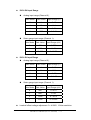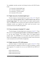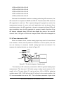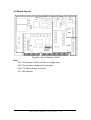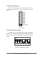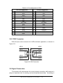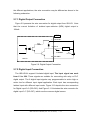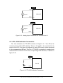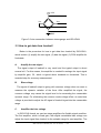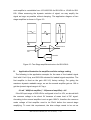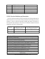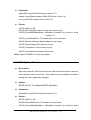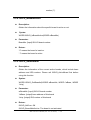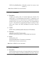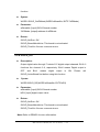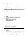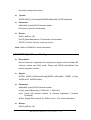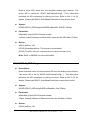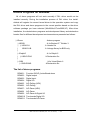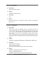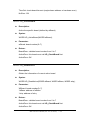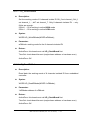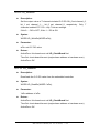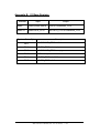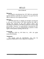
1
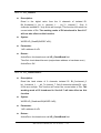
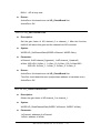
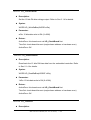
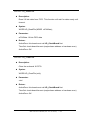
ISO-LD
User’s Manual
Warranty
All products manufactured by ICP DAS are warranted
against defective materials for a period of one year from the
date of delivery to the original purchaser.
Warning
ICP DAS assumes no liability for damages consequent
to the use of this product. ICP DAS reserves the right to
change this manual at any time without notice. The
information furnished by ICP DAS is believed to be accurate
and reliable. However, no responsibility is assumed by ICP
DAS for its use, or for any infringements of patents or other
rights of third parties resulting from its use.
Copyright
Copyright 2003 by ICP DAS Co., LTD. All rights
reserved worldwide.
Trademark
The names used for identification only may be
registered trademarks of their respective companies.
ISO-LD User’s Manual (Ver :2.4 02/12/04) -----1
Contents
1. GENERAL INFORMATION ............................................ 4
1.1 INTRODUCTION ......................................................................... 4
1.2 FEATURES ............................................................................... 4
1.3 SPECIFICATIONS ....................................................................... 4
1.4 GENERAL SPECIFICATIONS ........................................................ 6
1.5 PRODUCT CHECK LIST .............................................................. 6
2. HARDWARE CONFIGURATION ................................... 8
2.1 THE BLOCK DIAGRAMS .............................................................. 8
2.1.1 Eight channels of isolated digital input ...........................................9
2.1.2 Seven channels of isolated O.C. output ...........................................9
2.1.3 Eight channels of TTL/LED indicator .............................................9
2.1.4 Two channels of AD............................................................................10
2.2 BOARD LAYOUT ...................................................................... 12
2.3 IRQ CHANNEL SELECTION ...................................................... 13
2.4 I/O BASE ADDRESS SETTING ................................................... 13
2.5 CONNECTOR PIN ASSIGNMENT ................................................ 14
2.6.1 CN1 Connector ...................................................................................14
2.6.2 CN2 Connector ...................................................................................15
2.6.3 CN3 Connector ...................................................................................16
2.6 SIGNAL CONNECTION .............................................................. 16
2.7.1 Digital Output Connection ...............................................................17
2.7.2 Digital Input Connection ..................................................................17
2.7.3 Analog Input Connection..................................................................18
2.7.4 TTL/LED Indicator Connection ......................................................19
2.8 CALIBRATION .......................................................................... 20
3. FUNCTION OPERATION OF LOADCELL................... 21
3.1 WHAT IS LOADCELL................................................................. 21
3.2 LOADCELL INPUT CONNECTION ................................................ 21
3.3 HOW TO GET DATA FROM LOADCELL ......................................... 22
3.4 WHY NEED 2 CHANNELS .......................................................... 24
4. SOFTWARE INSTALLATION ...................................... 25
5. INSTALLATION DLL DRIVER ..................................... 26
ISO-LD User’s Manual (Ver :2.4 02/12/04) -----2
5.1 TABLE OF ERRORCODE AND ERRORSTRING ............................. 26
5.2 DLL FUNCTION DEFINITION AND DESCRIPTION .......................... 27
5.2.1 ISOLD_GetDllVersion ......................................................................28
5.2.2 ISOLD_ActiveBoard ..........................................................................28
5.2.3 ISOLD_CloseBoard ...........................................................................29
5.2.4 ISOLD_IsBoardActive.......................................................................30
5.2.5 ISOLD_GetBoardInf ..........................................................................30
5.2.6 ISOLD_SetDIMode ............................................................................31
5.2.7 ISOLD_GetDIMode ...........................................................................31
5.2.8 ISOLD_DO...........................................................................................32
5.2.9 ISOLD_ReadbackDO ........................................................................33
5.2.10 ISOLD_DI ..........................................................................................33
5.2.11 ISOLD_GetLatchDI .........................................................................34
5.2.12 ISOLD_ClearLatchDI .....................................................................34
5.2.13 ISOLD_SetChannelConfig .............................................................35
5.2.14 ISOLD_GetChannelConfig ............................................................36
5.2.15 ISOLD_SetDABias ...........................................................................36
5.2.16 ISOLD_GetDABias ..........................................................................37
5.2.17 ISOLD_ADPollingHex ...................................................................37
5.2.18 ISOLD_ADPolling ...........................................................................38
5.2.19 ISOLD_ADsPacerHex ....................................................................39
5.2.20 ISOLD_ADsPacer ............................................................................40
5.2.21 ISOLD_SetLED ................................................................................40
5.2.22 ISOLD_GetLED ...............................................................................41
6. DEMO PROGRAMS FOR WINDOWS ......................... 42
APPENDIX....................................................................... 49
APPENDIX A. RELATED DOS SOFTWARE...................................... 49
A-1 Where is the related software.............................................................49
A-2 LIB Function Description ...........................................................................50
APPENDIX B. IO BASE REGISTER................................................. 63
ISO-LD User’s Manual (Ver :2.4 02/12/04) -----3
1.General Information
1.1 Introduction
The ISO-LD series is an ISA bus-type isolated loadcell DAQ board. The
isolation inputs can be operated with up to 500Vrms of common-mode voltage.
The common application of ISO-LD series board is suitable for static force
measurement and dynamic force analysis. Because there are on board
excitation voltage (DC 12V) and high gain amplifier, users do not have to buy
any extra power supply and signal-conditioning module. In other words, it saves
your money and space. The special features are giving as following:
1.2 Features
ISA BUS interface;
500Vrms photo-isolation protection;
One strain gauge input channel (channel 1) ;
One analog input channel (channel 0) ;
Build-in 1K bytes FIFO;
Provide excitation voltage (DC12V, 50mA) for loadcell instrument;
The input gain of strain gauge can be up to 40,000;
Programmable 12 bit resolution DC offset voltage (0 ~-4.096V) ;
A built-in second order low pass filter ;
Direct connection to strain gauge type loadcell;
8 channels 12~24V isolated digital input;
7 channels isolated open-collector (NPN type) digital output;
Programmable 8 bits LED indicator for analog input signal magnitude.
1.3 Specifications
Analog Inputs
A/D converter with resolution: 12 bits, unipolar
Conversion rate: 20KS/s max.
Input Impedance:10,000MΩ||6pF
Recommend warm-up time: 10 minutes
ISO-LD User’s Manual (Ver :2.4 02/12/04) -----4
ISO-LDH Input Range
Analog input range (Channel 0):
Gain Mode
Gain Value
Input Range (V)
0
1
0~10
1
10
0~1
2
100
0~0.1
3
1000
0~0.01
Strain gauge input range (Channel 1):
Gain Mode Gain Value Input Range (mV)
0
400
0~37.5
1
4,000
0~15
2
40,000
0~12.75
ISO-LDL Input Range
Analog input range (Channel 0):
Gain Mode
Gain Value
Input Range (V)
0
1
0~10
1
2
0~5
2
4
0~2.5
3
8
0~1.25
Strain gauge input range (Channel 1):
Gain Mode Gain Value Input Range (mV)
0
400
0 ~37.5
1
800
0 ~25
2
1,600
0 ~18.75
3
3,200
0~15.625
Loadcell offset voltage adjustment: 0~-4.096V, 12 bits resolution.
ISO-LD User’s Manual (Ver :2.4 02/12/04) -----5
Digital Inputs
8 channels photo-isolated 12~24V digital input.
Digital Outputs
7 channels isolated open-collector (NPN) digital output (100mA);
8 bits TTL/LED for the indication of analog input magnitude.
Optional daughter board
The DN-25 screw terminal board with D-Sub 9-pin and 25-pin cables is
provided for easy wire connection with the controlled device or
equipment.
This daughter board is not the standard component
included in ISO-LD package.
1.4 General Specifications
Bus Type: ISA Bus;
Connector: One 9-pin and one 25-pin D-type female connectors;
Operating temp: 0~50ºC;
Storage temp: -20ºC ~ 70ºC;
Humidity: 0~90% non-condensing;
Dimensions: 183mm×115mm.
1.5 Product Check List
In addition to this manual, the package includes the following items:
ISO_LD multifunction card;
Software CD ROM;
User’s manual.
It is recommended to read the release note firstly. All importance
information will be given in the release note as follows:
Where you can find the software driver, utility and demo programs.
How to install software & utility.
Where is the diagnostic program?
FAQ and answer.
ISO-LD User’s Manual (Ver :2.4 02/12/04) -----6
Attention !
If any of these items is missing or damaged, please contact your
local field agent. Save the shipping materials and carton in case you
want to ship or store the product in the future.
ISO-LD User’s Manual (Ver :2.4 02/12/04) -----7
2.Hardware Configuration
This section will describe the hardware setting of the ISO-LD, which
includes ISO-LDH and ISO-LDL.
2.1 The Block Diagrams
The block diagram of ISO-LD series is shown in below:
Figure2.1: The block diagram of ISO_LD.
The Host PC(X86) can send one control command to the queue through
ISA bus. The embedded controller will automatically read and execute this
command. The results of this command will also store in the data FIFO,
therefore the X86 can read back and analysis the results through ISA bus. The
Host PC(X86) site and the embedded controller is fully isolated. Therefore the
noise from external device will be isolated from X86, this will improve the Host
PC reliability.
In general, the Host PC only needs to send out command and then the
embedded controller will handle the control work in details. The features of
command set system are given as following:
(1) : reduce X86 load
(2) : easy programming
(3) : OEM/ODM special require function is easy to implement
ISO-LD User’s Manual (Ver :2.4 02/12/04) -----8
The embedded controller provides the following functions with ISO-LD series
board:
(1) 8 channels of isolated digital input
(2) 7 channels of isolated O.C. output
(3) 8 channels of TTL/LED indicator
(4) 2 channels of AD converter
2.1.1 Eight channels of isolated digital input
The block diagram of isolated digital input is given in Sec. 2.7.2. These DI
can be used as general purpose input or special purpose input such as
external trigger signal. This version firmware only support general purpose
input. The OEM/ODM user can specify their special requirement; therefore the
embedded controller can implement the detail control and provide a new
command set for Host PC(X86) site application.
2.1.2 Seven channels of isolated O.C. output
The block diagram of isolated digital input is also given in Sec.2.7.1. These
DOs can be used as general purpose output or special purpose output such
as “real time alarm indicator”. This firmware version only supports general
purpose output. The OEM/ODM user can specify their special requirement;
therefore the embedded controller can implement the detail control and provide
a new command set for Host PC(X86) site application.
2.1.3 Eight channels of TTL/LED indicator
The block diagram of isolated digital input is given in Sec.2.7.4. These
TTL/LED indicators are designed to connect to 8 LEDs for indication of analog
input magnitude. For example, the user can set BASE=123 and DELTA=10,
then
LED1 will ON if AD>123
LED2 will ON if AD>123+10
LED3 will ON if AD>123+20
ISO-LD User’s Manual (Ver :2.4 02/12/04) -----9
LED4 will ON if AD>123+30
LED5 will ON if AD>123+40
LED6 will ON if AD>123+50
LED7 will ON if AD>123+60
LED8 will ON if AD>123+70
Because the embedded controller is always performing AD conversion, the
AD value will be compared to BASE and DELTA. Therefore the LEDs show the
AD magnitude in real time. This is special designed for people to monitor the
measurement process. In some real world application such as dynamic force
monitoring system, the AD magnitude is dynamic changed and these LEDs will
also dynamically show the AD magnitude for people to watch. Note that if the
AD channel changed, these LEDs will also display the value of the new AD
channel. Also, if the gain or DC bias is changed, these LEDs will be changed too.
2.1.4 Two channels of AD
When we measure force, another analog signal may need to be monitored
as a function of force, such as position or distance. In such a system, the user
can use channel_1 to measure loadcell analog input and use channel 0 to
measure the relative indicator, as shown in Figure 2.2.
+12V
GND
Channel_0
Mux
G2
ADC
G1
Controller
Channel_1
Bias
DAC 1
Figure2.2: The block diagram of analog input
The channel_0 AD is directly connected to MUX for general analog input
measurement. The channel_1 AD (strain gauge analog input) connect to G1
amplify in first. The gain factor, G1, can be set from 100 to 10000 by adjusting
variable resistor VR2. If VR2 is fixed, the G1 is fixed. In the normal condition, the
G1 is recommended to be set as 400. This is the base parameter of gain value
ISO-LD User’s Manual (Ver :2.4 02/12/04) -----10
in Strain gauge input range.
The 12 bits DAC can provide 0V to -4.096V DC bias offset voltage by
software. This function provides a way to remove the DC level offset and then
the G2 will only amplify the AC signal. Besides, the G2 is PGA (Programmable
gain amplifier). In ISO-LDL, G2 can be configured as 1/2/4/8. In ISO-LDH, G2
can be configured as 1/10/100/1000. The ADC is 12 bits resolution for 0 to 10V
range in unipolar. The processes of analog input measurement for channel_0
and channel_1 are shown in below:
The steps for channel_0 AD conversion is given as following:
(1) select channel_0
(2) set G2 of PGA
(3) performance the AD conversion
The steps for channel_1 AD conversion is given as following:
(1)
(2)
(3)
(4)
(5)
set G1 in proper value (use VR2, not software programmable)
select channel_1
set DAC to remove the DC level of AD channel_1
select G2 to amplify the AC signal
performance the AD conversion
Note that the result of analog input value is always compared to BASE and
DELTA to indicate the analog input level. (refer Sec. 2.1.3)
In summary, A/D Offset and gain adjustment of the ISO_LD board are set
by the following two variable resistors.
VR1: AD offset adjustment for analog input channel_1 & channel_2.
VR2: G1 gain adjustment. Changing this VR value can change
amplifier gain from 100 to 10000.
ISO-LD User’s Manual (Ver :2.4 02/12/04) -----11
2.2 Board Layout
CN3
VR1
VR2
CN1
JP1
Figure2.3 ISO-LD Board LAYOUT
Note:
CN1: The terminal of A/D converter for voltage input
CN2: The terminal of digital input and output
CN3: TTL/LED indicator connector
JP1: IRQ selection
ISO-LD User’s Manual (Ver :2.4 02/12/04) -----12
CN2
2.3 IRQ Channel Selection
Figure 2.4 demonstrates the interrupt selection by the
hardware selection jumper JP1. The factory setting is NO interrupt
setting.
IRQ3
IRQ4
IRQ5
IRQ6
IRQ7
IRQ9
IRQ10
IRQ11
IRQ12
IRQ14
IRQ15
NC (Default)
JP1
Figure2.4 JP1
2.4 I/O Base Address setting
The ISO-LD can be configured as the one of 8 consecutive
locations in I/O address space from BASE to BASE+7 by the DIP
switch, as shown in Figure 2.5 and table 2.1. The default setting is
0x220:
ON
1
2
3
4
5
6
A8
A7
A6
A5
A4
NC
Figure2.5 Base Address DIP Switch
ISO-LD User’s Manual (Ver :2.4 02/12/04) -----13
Table 2.1: Base Address setting
Base Addr
A8
A7
A6
A5
A4
200
210
220
230
250
:
300
:
3F0
On
On
On
On
On
:
Off
:
Off
On
On
On
On
On
:
On
:
Off
On
On
On
On
Off
:
On
:
Off
On
On
Off
Off
On
:
On
:
Off
On
Off
On
Off
Off
:
On
:
Off
2.5 Connector Pin Assignment
The ISO-LD is equipped with two sets of 9-pin and 25-pin D-type female
connectors for wire connection of the I/O signal. The connector’s pin assignment
is specified as follows:
2.6.1 CN1 Connector
CN1 is 9 pin D-sub female connector for analog input/output, shown in
Figure 2.6. The detail pin assignment is presented in Table 2.2.
+ 1 2 V (E x c ita tio n + )
G N D (E x c ita tio n -)
1
2
6
V in 1 +
7
V in 1 -
3
4
5
8
V in 0
9
Figure2.6 Pin assignment CN1
ISO-LD User’s Manual (Ver :2.4 02/12/04) -----14
Table 2.2: Pin assignment of CN1
CN1 pin assignment
1
+12V DC Output
2
Vin1+
3
No Use
4
No Use
5
No Use
6
GND
7
Vin1-
8
Vin0
9
No Use
2.6.2 CN2 Connector
CN2 is 25-pin D-sub female connector for Digital input/output connector, as
shown in Figure 2.7. The detail pin assignment is provided in Table 2.3.
DI0+
DI1+
DI2+
DI.COM
DI4DI6DO.COM
DO0
DO2
DO4
DO6
DI0DI1DI2DI3DI5DI7DO.GND
DO1
DO3
DO5
+12V
GND
Figure2.7 CN2 Connector
ISO-LD User’s Manual (Ver :2.4 02/12/04) -----15
Table 2.3: Pin assignment of CN2
CN1 pin assignment
CN2 pin assignment
1
DI0+
14
DI0-
2
DI1+
15
DI1-
3
DI2+
16
DI2-
4
DI.COM
17
DI3-
5
DI4-
18
DI5-
6
DI6-
19
DI7-
7
DO.COM
20
DO.GND
8
DO0
21
DO1
9
DO2
22
DO3
10
DO4
23
DO5
11
DO6
24
+12V DC
12
+12V DC
25
GND
13
GND
2.6.3 CN3 Connector
CN3 is10 pins male connector for 8 LEDs indicator application, as shown in
Figure 2.8.
LED3
LED5
LED1
LED7
+5V
LED0
LED6
LED2
LED4
Figure2.8 CN3 Connector
2.6 Signal Connection
This section will demonstrate the correct signal connection skill because it
plays an important role for sending and receiving data accurately. According to
ISO-LD User’s Manual (Ver :2.4 02/12/04) -----16
the different applications, the wire connection may be different as shown in the
following subsection.
2.7.1 Digital Output Connection
Figure 2.9 presents the wire connection for digital output from ISO-LD. Note
that the current limitation of isolated open-collector (NPN) digital output is
100mA.
CN2
7
DO.COM
8
DO.0
-
Load
I
I <100mA
+
DC
12V~24V
20 DO.GND
ISO-LD
Figure 2.9: Digital Output Connection
2.7.2 Digital Input Connection
The ISO-LDH/L support 8 isolated digital input. The input signal can work
from 12 to 24V. These signals are suitable for connecting with relay or PLC
digital output. The 8 digital input signals may programmable to active high or
active low for different input signal application. Each input has corresponding
latched input with different input mode. Figure 2.10 depicts the wire connection
for Digital input 0~3 (DI0~DI2). And Figure 2.11 illustrates the wire connector for
digital input 3~7 (DI3~DI7), which use the common digital source.
ISO-LD User’s Manual (Ver :2.4 02/12/04) -----17
CN2
+5V
DI0+
1
DI0-
14
DI0
Figure 2.10: Digital Input Connection (DI0~DI2)
CN2
+5V
DI.COM
4
DI3
17
DI3
Figure 2.11: Digital Input Connection (DI3~DI7)
2.7.3 Analog Input Connection
The wire connection for analog input is demonstrated in Figure 2.12.
Because analog input channel 0 is provided for general application, single-end
method is adopted for analog input wire connection. Due to the channel 1 is
applied for strain gauge signal, the differential signal wire connection is used for
more precise signal measurement by reducing noise influence, as shown in
Figure 2.12.
ISO-LD User’s Manual (Ver :2.4 02/12/04) -----18
CN1
Vin0
8
+
Signal
ISO-LD
GND
6
CN1
Vin1+
2
+
Signal
ISO-LD
Vin1-
7
Figure 2.12: Analog Input Connection for channel 0 and 1
2.7.4 TTL/LED Indicator Connection
The wire connection for TTL/LED is shown in Figure 2.13. The +5V is the
common source of the LED indicator. That is, +5V need to be connected to the
anode of the LED. And then the cathode of each LEDs needs to be connected
to the corresponding LED pin. The Pin of TTL/LED is controller by analog input
measurement to turn ON or OFF the corresponding LED indicators, as shown in
Figure 2.13.
CN3
+5V
ISO-LD
LED0
Figure 2.13:TTL/LED Indicator Connection
ISO-LD User’s Manual (Ver :2.4 02/12/04) -----19
2.8 Calibration
Calibration method is provided in section 2.1.4 by hardware setting of
variable resistor VR1 and VR2. The VR1 provides the function to adjusting the
offset bias voltage for DC analog input level. And VR2 is used to configure the
G1 gain from 100 to 10000. Note that only the “Relative Value” is interesting for
analog input calibration. And it must be performed based on their G1 gain
setting. Therefore, the “Relative Value” calibration is more important than “Real
Value” under the consideration of strain gauge application.
ISO-LD User’s Manual (Ver :2.4 02/12/04) -----20
3. Function Operation of Loadcell
3.1 What is Loadcell
Loadcell is one kind of bridge sensor and stands as a passive resistant
sensor. The resistance value is dependent on the change of the force. Figure
3.1 depicts the wire connection of stress gauge sensor. The excitation source
may be voltage or current source. The V+ and V- is the differential voltage
output, whose value is proportional to the force. Typically the difference between
V+ and V- is about several mV signal level.
Excitation source+
V-
V+
Excitation source-
Figure 3.1 the bridge sensor of stress gauge.
3.2 Loadcell Input Connection
The ISO-LDH/L can be connected to a loadcell which is powered by
excitation voltage. The ISO-LDH/L has the on-board excitation +12V voltage
source for loadcell excitation source. The V+/V- can be used to connect to the
input Vin+/Vin- of analog input channel 1 on ISO-LDH/L. The wire connection
method is demonstrated in Figure 3.2.
ISO-LD User’s Manual (Ver :2.4 02/12/04) -----21
+12V
Vin-
Vin+
GND
Figure 3.2 wire connection between stress gauge and ISO-LDH/L
3.3 How to get data from Loadcell
Below is the procedure for how to get data from loadcell by ISO-LDH/L,
which include (1) amplify the raw signal, (2) bias the signal, (3) PGA amplifier for
final dada.
A.
Amplify the raw signal
The signal output of loadcell is very small and the typical output is about
several mV. For this reason, the amplifier is needed for enlarge the input signal
by amplifier gain, G1, which is typical about hundreds to thousands. This is
essential step for accuracy measurement.
B.
Bias voltage
The signal of loadcell output is going with common voltage when we want to
measure the dynamic variation of the force. After amplified the signal, the
common voltage may cause the signal level to be exceeding the measurable
dynamic range. For eliminating the common mode voltage effect, an extra bias
voltage is provided to adjust the AC signal of loadcell signal into the measurable
range.
C.
Amplifier the bias voltage
In ISO-LDH/L board, we use two stage amplifiers for flexible signal condition.
The first amplifier, which is fixed gain, with digital controllable bias voltage can
adjust the input signal from loadcell to the suitable range for next amplifier. The
ISO-LD User’s Manual (Ver :2.4 02/12/04) -----22
next amplifier is controllable from 1/10/100/1000 for ISO-LDH or 1/2/4/8 for ISOLDL. When measuring the dynamic variation of signal, we may amplify the
signal as large as possible without clamping. The application diagram of two
stage amplifiers is shown in Figure 3.3.
Vin+
Fix Gain
Digital Control
Amp1
Amp2
VinBias
12-bit DA
voltage
Figure 3.3 Two Stage amplifiers structure for ISO-LDH/L
D.
Application illustration for amplifier and bias voltage setting
The following is the application example for the case of the loadcell signal
2mV with 0.1mV Vp-p, and ISO-LDH selected for loadcell signal acquisition. The
first amplifier is fixed as the gain 400 V/V( factory setting). For geting the
maximum dynamic readable range, we set the second amplifier gain as 100 to
get the dynamic signal range in 4V Vp-p.
0.1mV * 400(first amplifier) * 100(second amplifier) = 4V
If the AD input range of ISO-LDH is configured to be 0 to 10V, we should shift
the common voltage to be about 5V because of mean level of DC signal.
According to the second amplifier is set as gain 100V/V, therefore the common
mode voltage of first amplifier need to be 50mV before the second stage
amplifying. To meet this requirement, the bias voltage needs to be set as
ISO-LD User’s Manual (Ver :2.4 02/12/04) -----23
750mV, as description in below.
2mV * 400 - 750mV = 50mV
50mV * 100 =5V
3.4 Why need 2 channels
We often use another analog indicator like position or distance to show the
physical change by the force when measuring the strain gauge. In such a
system, the user can use channel_1 to measure loadcell analog input and use
channel 0 to measure the relative indicator.
ISO-LD User’s Manual (Ver :2.4 02/12/04) -----24
4. Software Installation
The ISO-LD can be used in DOS and Windows 98/Me/NT/2000/XP. For these
Windows operation systems, the recommended installation steps are given
as below:
Step 1: Insert the companion CD into the CD-ROM driver and wait a few
seconds until the installation program starts automatically. If it
cannot be started automatically for some reasons, please doubleclick the file \NAPDOS\AUTO32.EXE in this CD.
Step 2: Click the first item; Toolkits (Software) / Manuals.
Step 3: Click the item ISA Bus DAQ Card.
Step 4: Click ISO-LD (LDL/LDH).
Step 5: Click “install Toolkit for Windows 98 (Or Me, NT, 2000, XP, DOS)”.
Then, the InstallShield will start the driver installation process to copy the
related material to the indicated directory and register the driver on your
computer. The driver target directory is as below for different system.
Windows NT/2000 – WINNT\SYSTEM32\DRIVERS
Windows 98/Me/XP – WINDOWS\SYSTEM32\DRIVERS
ISO-LD User’s Manual (Ver :2.4 02/12/04) -----25
5. Installation DLL Driver
The DLL driver is the collection of function calls of the ISO-LD cards for
Windows 98/Me/NT/2000/XP system. The application structure is presented as
following figure. The user application program developed by designate tools like
VB, Delphi and Borland C++ Builder can call ISOLD.DLL driver in user mode.
And then DLL driver will bypass the function call to Windrvr6.sys to access the
hardware system.
VB / Delphi / BCB
program
user mode
ISOLD.DLL
Windrvr6.sys
(for NT/98/Me/2000/XP)
kernel mode
ISO-LD hardware
5.1 Table of ErrorCode and ErrorString
Error Code
Error ID
Comment
0
ISOLD_NoError
OK
1
ISOLD_ActiveBoardError
This board can not be activated.
2
ISOLD_ ExceedMaxBoardNum
3
ISOLD_BaseOverRange
The board number exceeds the
maximum board number (7).
Base address is over range.
4
ISOLD_BaseOverlap
Base address overlap.
ISO-LD User’s Manual (Ver :2.4 02/12/04) -----26
5
ISOLD_DriverNoOpen
Kernel driver can’t be found.
6
ISOLD_BoardIsNotActive
The board is not activated
8
ISOLD_ParameterError
Parameter is null or out of range
9
ISOLD_IrqNumError
IRQ number is illegal.
10
ISOLD_BoardIsActive
Board is active now.
11
ISOLD_TimeOut
Execute command timeout.
5.2 DLL Function Definition and Description
All of the functions provided for ISO-LD are listed in the following table and the
detail information for every function will be presented in the following sub-section.
However, in order to make the description simplify and clearly, the attribute of
the input and output parameter of the function is indicated as [input] and [output]
respectively, as shown in following table.
Keyword
Set parameter by user before Get the data from this parameter
calling this function?
after calling this function?
[ input ]
Yes
No
[ output ]
No
Yes
Function definition
WORD ISOLD_GetDllVersion();
WORD ISOLD_ActiveBoard(WORD wBoardNo, WORD wBase, WORD wIrq)
WORD ISOLD_CloseBoard(WORD wBoardNo);
WORD ISOLD_IsBoardActive(WORD BoardNo);
WORD ISOLD_GetBoardInf(WORD BoardNo, WORD wBase, WORD wIrq);
WORD ISOLD_SetDIMode(WORD wBoardNo,BYTE bDIMode);
WORD ISOLD_GetDIMode(WORD wBoardNo,BYTE *bDIMode);
WORD ISOLD_DO(WORD wBoardNo,BYTE wDO);
WORD ISOLD_ReadbackDO(WORD wBoardNo,BYTE *bDO);
WORD ISOLD_DI(WORD wBoardNo,BYTE *bDI);
WORD ISOLD_GetLatchDI(WORD wBoardNo,BYTE *bDI);
WORD ISOLD_ClearLatchDI(WORD wBoardNo,BYTE bChannel);
WORD ISOLD_SetChannelConfig(WORD wBoardNo, WORD wType, WORD wCH,
WORD wGain);
ISO-LD User’s Manual (Ver :2.4 02/12/04) -----27
WORD ISOLD_GetChannelConfig(WORD wBoardNo, WORD *wType, WORD
*wCH,WORD *wGain);
WORD ISOLD_SetDABias(WORD wBoardNo, WORD wDA);
WORD ISOLD_GetDABias(WORD wBoardNo, WORD *wDA);
WORD ISOLD_ADPollingHex(WORD wBoardNo, WORD *wData);
WORD ISOLD_ADPolling(WORD wBoardNo,float *fData);
WORD ISOLD_ADsPacerHex(WORD wBoardNo, WORD *wData,WORD wNum,
WORD wSamplingRate);
WORD ISOLD_ADsPacer(WORD wBoardNo, float *fData, WORD wNum, WORD
wSamplingRate);
WORD ISOLD_SetLED(WORD wBoardNo, BYTE bBase, BYTE bDelta);
WORD ISOLD_GetLED(WORD wBoardNo, BYTE *bBase, BYTE *bDelta);
5.2.1 ISOLD_GetDllVersion
Description:
Obtain the version information of ISOLD.DLL driver.
Syntax:
WORD ISOLD_GetDllVersion(viod)
Parameter:
None
Return:
DLL version information. For example: If 101(hex) is return, it means
driver version is 1.01.
5.2.2 ISOLD_ActiveBoard
Description:
Activate the device. It must be called once before using the other
functions of ISO-LD board.
Syntax:
WORD ISOLD_ActiveBoard(WORD wBoardNo, WORD wBase, WORD
wIrq)
ISO-LD User’s Manual (Ver :2.4 02/12/04) -----28
Parameter:
wBoardNo: [input] ISO-LD board number (0~7).
wBase: [input] Base address (200h~3F0h,refer to Sec 2.4).
wIrq: [input] IRQ number (refer to Sec 2.3)
Return:
ISOLD_NoError: OK
ISOLD_DriverNoOpen: Kernel driver can not be found.
ISOLD_ExceedMaxBoardNum: wBoardNo exceeds the maximum board
number (7).
ISOLD_ActiveBoardError: This board can not be activated.
ISOLD_BaseOverRange: Base address is over range.
ISOLD_BaseOverlap: Base address overlap
ISOLD_IrqNumError: IRQ number is illegal..
ISOLD_BoardIsActive: Board is active now.
Note: Refer to DEMO1 for more information.
5.2.3 ISOLD_CloseBoard
Description:
Stop and close the ISO-LD kernel driver and release the device resource
from computer device resource. This method must be called once before
exiting the user's application program.
Syntax:
WORD ISOLD_CloseBoard(WORD wBoardNo)
Parameter:
wBoardNo: [input] ISO-LD board number (0~7).
Return:
ISOLD_NoError: OK
ISOLD_BoardIsNotActive: The board is not activated
ISOLD_ExceedMaxBoardNum: wBoardNo exceeds the maximum board
ISO-LD User’s Manual (Ver :2.4 02/12/04) -----29
number (7).
5.2.4 ISOLD_IsBoardActive
Description:
Obtain the information about the specific board is active or not.
Syntax:
WORD ISOLD_IsBoardActive(WORD wBoardNo)
Parameter:
BoardNo: [input] ISO-LD board number
Return:
“0” means the board is inactive.
“1” means the board is active.
5.2.5 ISOLD_GetBoardInf
Description:
Obtain the information of the current active boards, which include base
address and IRQ number. Please call ISOLD_ActiveBoard first before
using this function.
Syntax:
WORD ISOLD_GetBoardInf(WORD wBoardNo, WORD *wBase, WORD
*wIrq)
Parameter:
wBoardNo: [input] ISO-LD board number
*wBase: [output] base address of this board
*wIrq: [output] IRQ number of this board
Return:
ISOLD_NoError: OK
ISOLD_BoardIsNotActive: The board is not activated
ISO-LD User’s Manual (Ver :2.4 02/12/04) -----30
ISOLD_ExceedMaxBoardNum: wBoardNo exceeds the maximum board
number (7).
Note: Refer to DEMO1 for more information.
5.2.6 ISOLD_SetDIMode
Description:
Configure the working mode of 8 isolated digital input channels. The
setting of Bit 0 ~7 is corresponding to the channel 0~7, respectively, If the
corresponding bit is set to 0, that means the corresponding DI channel is
working on active Low mode. On the other hand, if the corresponding bit
is set to 1, that means the corresponding DI channel is working on active
HIGH mode. Please call ISOLD_ActiveBoard first before using this
function.
Syntax:
WORD ISOLD_SetDIMode(WORD wBoardNo, BYTE bDIMode)
Parameter:
wBoardNo: [input] ISO-LD board number
bDIMode: [input] working mode of 8 isolated digital input channels
Return:
ISOLD_NoError: OK
ISOLD_BoardIsNotActive: This board is not activated
ISOLD_TimeOut: Execute command timeout.
Note: Refer to DEMO3 for more information.
5.2.7 ISOLD_GetDIMode
Description:
Get the working mode information of 8 isolated digital input channels from
ISO_LD board. Please call ISOLD_ActiveBoard first before using this
ISO-LD User’s Manual (Ver :2.4 02/12/04) -----31
function.
Syntax:
WORD ISOLD_GetDIMode(WORD wBoardNo, BYTE *bDIMode)
Parameter:
wBoardNo: [input] ISO-LD board number
*bDIMode: [output] address of wDIMode
Return:
ISOLD_NoError: OK
ISOLD_BoardIsNotActive: This board is not activated
ISOLD_TimeOut: Execute command timeout.
5.2.8 ISOLD_DO
Description:
Output digital value through 7 isolate O.C digital output channels. Bit 0~6
functions the channel 0~6, respectively. Bit=0 means Digital output is
OFF
and
Bit=1
means
digital
output
is
ISOLD_ActiveBoard first before using this function.
Syntax:
WORD ISOLD_DO(WORD wBoardNo, BYTE bDO)
Parameter:
wBoardNo: [input] ISO-LD board number
bDO: [input] digital output value
Return:
ISOLD_NoError: OK
ISOLD_BoardIsNotActive: This board is not activated
ISOLD_TimeOut: Execute command timeout.
Note: Refer to DEMO2 for more information.
ISO-LD User’s Manual (Ver :2.4 02/12/04) -----32
ON.
Please
call
5.2.9 ISOLD_ReadbackDO
Description:
Read back the O.C digital output value from the embedded controller of
ISO-LD board. Please call ISOLD_ActiveBoard first before using this
function.
Syntax:
WORD ISOLD_ReadbackDO(WORD wBoardNo, BYTE *bDO)
Parameter:
wBoardNo: [input] ISO-LD board number
*bDO: [output] address of bDO
Return:
ISOLD_NoError: OK
ISOLD_BoardIsNotActive: This board is not activated
ISOLD_TimeOut: Execute command timeout.
Note: Refer to DEMO2 for more information
5.2.10 ISOLD_DI
Description:
Obtain the 8 isolated digital input values from the ISO-LD board. Bit 0 ~7
correspondingly stands as the channel 0~7, respectively. The DI working
mode introduced in Sec 5.2.6 will take effect on this function. Please call
ISOLD_ActiveBoard first before using this function.
Syntax:
WORD ISOLD_DI(WORD wBoardNo,BYTE *bDI)
Parameter:
wBoardNo: [input] ISO-LD board number
*bDI: [output] address of bDI
ISO-LD User’s Manual (Ver :2.4 02/12/04) -----33
Return:
ISOLD_NoError: OK
ISOLD_BoardIsNotActive: This board is not activated
ISOLD_TimeOut: Execute command timeout.
Note: Refer to DEMO3 for more information.
5.2.11 ISOLD_GetLatchDI
Description:
Obtain the 8 isolated digital input latch states from hardware. Bit 0 ~7
depicts the status of the channel 0~7, respectively. The DI working mode
introduced in Sec 5.2.6 will not take effect on this function. Please call
ISOLD_ActiveBoard first before using this function.
Syntax:
WORD ISOLD_GetLatchDI(WORD wBoardNo,BYTE *bDI)
Parameter:
wBoardNo: [input] ISO-LD board number
*bDI: [output] address of bDI
Return:
ISOLD_NoError: OK
ISOLD_BoardIsNotActive: This board is not activated
ISOLD_TimeOut: Execute command timeout.
Note: Refer to DEMO3 for more information.
5.2.12 ISOLD_ClearLatchDI
Description:
Clear the latch states of 8 isolated digital input channels. Bit 0 ~7 is the
status of channel 0~7, respectively. bit=0 means the latch state is clear.
bit=1 means the latch state is not clear. Please call ISOLD_ActiveBoard
ISO-LD User’s Manual (Ver :2.4 02/12/04) -----34
first before using this function.
Syntax:
WORD ISOLD_ClearLatchDI(WORD wBoardNo, BYTE bChannel)
Parameter:
wBoardNo: [input] ISO-LD board number
bChannel: [input] the latch states.
Return:
SOLD_NoError: OK
ISOLD_BoardIsNotActive: This board is not activated
ISOLD_TimeOut: Execute command timeout.
Note: Refer to DEMO3 for more information.
5.2.13 ISOLD_SetChannelConfig
Description:
Set the channel configuration for analog input signal, which includes AD
channel number and Gain mode. Please call ISOLD_ActiveBoard first
before using this function.
Syntax:
WORD ISOLD_SetChannelConfig(WORD wBoardNo, WORD wType,
WORD wCH, WORD wGain)
Parameter:
wBoardNo: [input] ISO-LD board number
wType: [input] Board type. 0:ISO-LDL, 1: ISO-LDH.
wCH: [input] AD channel number. 0: channel 0(general), 1:channel
1(loadcell)
wGain: [input] Gain mode(0~4), Refer to Sec 1.3 for more information.
Return:
SOLD_NoError: OK
ISO-LD User’s Manual (Ver :2.4 02/12/04) -----35
ISOLD_BoardIsNotActive: This board is not activated
ISOLD_TimeOut: Execute command timeout (maybe hardware error)
ISOLD_ ParameterError: Parameter is null, out of range or invalid.
Note: Refer to DEMO5~DEMO9 for more information
5.2.14 ISOLD_GetChannelConfig
Description:
Obtain the information of analog input configuration for ISO-LD board,
including
AD
channel
number
and
gain
mode.
Please
call
ISOLD_ActiveBoard first before using this function.
Syntax:
WORD ISOLD_SetChannelConfig(WORD wBoardNo, WORD *wType,
WORD *wCH, WORD *wGain)
Parameter:
wBoardNo: [input] ISO-LD board number.
*wType: [output] address of wType
*wCH: [output] address of wCH
*wGain: [output] address of wGain
Return:
SOLD_NoError: OK
ISOLD_BoardIsNotActive: This board is not activated
ISOLD_TimeOut: Execute command timeout (maybe hardware error)
5.2.15 ISOLD_SetDABias
Description:
Set the 12 bits DA voltage output for DC bias adjustment. Refer to Sec
2.1.4 for more information. Please call ISOLD_ActiveBoard first before
using this function
ISO-LD User’s Manual (Ver :2.4 02/12/04) -----36
Syntax:
WORD ISOLD_SetDABias(WORD wBoardNo, WORD wDA)
Parameter:
wBoardNo: [input] ISO-LD board number.
wDA:
[input] 12 bits data (0~4095)
Return:
SOLD_NoError: OK
ISOLD_BoardIsNotActive: This board is not activated
ISOLD_TimeOut: Execute command timeout (maybe hardware error)
Note: Refer to DEMO7 and DEMO8 for more information
5.2.16 ISOLD_GetDABias
Description:
Obtain the information of the 12bits DA bias voltage output setting from
the embedded controller of ISO-LD board. Refer to Sec 2.1.4 for details.
Please call ISOLD_ActiveBoard first before using this function
Syntax:
WORD ISOLD_SetDABias(WORD wBoardNo, WORD *wDA)
Parameter:
wBoardNo: [input] ISO-LD board number.
*wDA: [output] address of wDA
Return:
SOLD_NoError: OK
ISOLD_BoardIsNotActive: This board is not activated
ISOLD_TimeOut: Execute command timeout (maybe hardware error)
5.2.17 ISOLD_ADPollingHex
Description:
ISO-LD User’s Manual (Ver :2.4 02/12/04) -----37
Read a 12-bit HEX value from the specified analog input channel. The
active AD is setting by ISOLD_SetChannelConfig(…).This subroutine
performs the AD conversion by polling one time. Refer to Sec 2.1.4 for
details. Please call ISOLD_ActiveBoard first before using this function
Syntax:
WORD ISOLD_ADPollingHex(WORD wBoardNo, WORD *wData)
Parameter:
wBoardNo: [input] ISO-LD board number
*wData: [output] address of wData which store the AD HEX data (12 bits)
Return:
SOLD_NoError: OK
ISOLD_BoardIsNotActive: This board is not activated
ISOLD_TimeOut: Execute command timeout (maybe hardware error)
Note: Refer to DEMO5 for more information
5.2.18 ISOLD_ADPolling
Description:
Read a decimal value of current active AD from the analog input channel.
The active AD is set by ISOLD_SetChannelConfig(…). This subroutine
performs the AD conversion by polling one time. Refer to Sec 2.1.4 for
details. Please call ISOLD_ActiveBoard first before using this function
Syntax:
WORD ISOLD_ADPolling(WORD wBoardNo, float *fData)
Parameter:
wBoardNo: [input] ISO-LD board number
*fData: [output] address of fData which store the AD data (12 bits).
Return:
SOLD_NoError: OK
ISO-LD User’s Manual (Ver :2.4 02/12/04) -----38
ISOLD_BoardIsNotActive: This board is not activated
ISOLD_TimeOut: Execute command timeout (maybe hardware error)
Note: Refer to DEMO6 for more information
5.2.19 ISOLD_ADsPacerHex
Description:
Read multiple HEX values of current active AD from the analog input
channel. The active AD is set by ISOLD_SetChannelConfig(…). This
subroutine performs the AD conversions by pacer trigger. Refer to Sec
2.1.4 for details. Please call ISOLD_ActiveBoard first before using this
function.
Syntax:
WORD ISOLD_ADsPacerHex(WORD wBoardNo, WORD *wData, WORD
wNum, WORD wSamplingRate)
Parameter:
wBoardNo: [input] ISO-LD board number
*wData: [output] starting address of wData which store the AD HEX data
(12 bits)
wNum: [input] number of AD conversions will be performed
wSamplingRate: [input] AD sampling rate (Hz)
Return:
SOLD_NoError: OK
ISOLD_BoardIsNotActive: This board is not activated
ISOLD_TimeOut: Execute command timeout (maybe hardware error)
ISOLD_ ParameterError: Parameter is null, out of range or invalid.
Note: Refer to DEMO7 for more information
ISO-LD User’s Manual (Ver :2.4 02/12/04) -----39
5.2.20 ISOLD_ADsPacer
Description:
Read multiple decimal values of current active AD from the analog input
channel. The active AD is set by ISOLD_SetChannelConfig(…). This
subroutine performs the AD conversions by pacer trigger. Refer to Sec
2.1.4 for details. Please call ISOLD_ActiveBoard first before using this
function
Syntax:
WORD ISOLD_ADsPacer(WORD wBoardNo, float *fData, WORD wNum,
WORD wSamplingRate)
Parameter:
wBoardNo: [input] ISO-LD board number
*fData: [output] starting address of wData which store the AD data (12
bits)
wNum: [input] number of AD conversions will be performed
wSamplingRate: [input] AD sampling rate (Hz)
Return:
SOLD_NoError: OK
ISOLD_BoardIsNotActive: This board is not activated
ISOLD_TimeOut: Execute command timeout (maybe hardware error)
ISOLD_ ParameterError: Parameter is null, out of range or invalid
Note: Refer to DEMO8 for more information
5.2.21 ISOLD_SetLED
Description:
Set the BASE and DELTA configuration of TTL/LED indicator. Refer to
Sec 2.1.3 for details.
Syntax:
ISO-LD User’s Manual (Ver :2.4 02/12/04) -----40
WORD ISOLD_SetLED(WORD wBoardNo, BYTE bBase, BYTE bDelta)
Parameter:
wBoardNo: [input] ISO-LD board number
bBase: [input] AD base value.
bDelta: [input] AD delta value.bBase+bDelta*7 must small than 255.
Return:
SOLD_NoError: OK
ISOLD_BoardIsNotActive: This board is not activated
ISOLD_TimeOut: Execute command timeout (maybe hardware error)
ISOLD_ ParameterError: Parameter is null, out of range or invalid
5.2.22 ISOLD_GetLED
Description:
Get the AD BASE and DELTA configuration value of TTL/LED indicator
from the embedded controller of ISO-LD board.
Syntax:
WORD ISOLD_GetLED(WORD wBoardNo, BYTE *bBase, BYTE *bDelta)
Parameter:
wBoardNo: [input] ISO-LD board number
*bBase: [output] address of bBase
*bDelta: [output] address of bDelta
Return:
SOLD_NoError: OK
ISOLD_BoardIsNotActive: This board is not activated
ISOLD_TimeOut: Execute command timeout (maybe hardware error)
ISO-LD User’s Manual (Ver :2.4 02/12/04) -----41
6.Demo Programs for Windows
All of demo programs will not work normally if DLL driver would not be
installed correctly. During the installation process of DLL driver, the installshields will register the correct kernel driver to the operation system and copy
the DLL driver and demo programs to the correct position based on the driver
software package you have selected (Win98,Me,NT,win2000,XP). After driver
installation, the related demo programs and development library and declaration
header files for different development environments are presented as follows.
|--\Demo
|--\BCB3
| |--\ISOLD.H
|
\ISOLD.LIB
|
|--\Delphi5
| |--\ISOLD.PAS
|
|--\VB6
|--\ISOLD.BAS
demo program
for Borland C++ Builder 3
Header file
Linkage library for BCB only
for Delphi 5
Declaration file
for Visual Basic 6
Declaration file
The list of demo programs:
DEMO1:
DEMO2:
DEMO3:
DEMO4:
DEMO5:
DEMO6:
DEMO7:
DEMO8
DEMO9:
DEMO10
DEMO11
Function ISOLD_ActiveBoard demo
Digital output
Digital input .
Digital I/O
A/D Polling (HEX)
A/D Polling
A/D Pacer (HEX)
A/D Pacer
A/D Pacer & Digital I/O
Two boards Digital I/O
Two boards A/D Pacer
ISO-LD User’s Manual (Ver :2.4 02/12/04) -----42
The brief introduction of demo programs
DEMO1:
Demo1 is the example for starting ISO-LD board. User needs to configure
the Base Address and IRQ based on the hardware switch setting. After
choosing the correct base address and IRQ setting, user can click the “Active”
button to let the hardware ISO-LD board work and see the hardware
information in the GetBoardInf window. Besides, user also can click “Inactive”
to release the hardware resource from operation system.
Figure 6.1: The form of demo_1 program
DEMO2: Digital Output
This example demonstrates the digital output function under the setting of
Base Address=:220h and IRQ=0. Click “ON” or “OFF” button on the
corresponding Digital Out channel to turn on or off the corresponding digital
output channel. By the way, clicking on ”Read” button can read back the
condition of digital output.
ISO-LD User’s Manual (Ver :2.4 02/12/04) -----43
Figure 6.2: The form of demo_2 program
DEMO2: Digital Input
This example demonstrates the digital input function under the setting of
Base Address=220h and IRQ=0. Click the “Get DI” button to obtain the status of
Digital Input. And clicking “Get Latch DI” button can obtain the digital value after
latched. User can select the digital input channel and click the “clear latch”
button to clear the latch value on the corresponding digital channel. Besides,
input the DI setting value into the text field and click “Set DI Mode” to configure
the Digital Input Active Mode for each digital channel. Furthermore, clicking on
“Get DI Mode” can obtain the current setting for Digital Input Active Mode.
Finally, click on “Exit” to exit the application.
Figure 6.3: The form of demo_3 program
ISO-LD User’s Manual (Ver :2.4 02/12/04) -----44
DEMO4: Digital Input and Output
DEMO4 demonstrates the digital input and output function under the setting
of Base Address=:220h and IRQ=0.
Figure 6.4: The form of demo_4 program
DEMO5: A/D Polling (HEX)
Demo5 illustrates the A/D Polling function of ISO-LD in HEX mode under the
hardware setting of Base Address=220h and IRQ=0.
Figure 6.5: The form of demo_5 program
DEMO6: A/D Polling
Demo6 illustrates the A/D Polling function of ISO-LD in decimal mode under
the hardware setting of Base Address=220h and IRQ=0.
ISO-LD User’s Manual (Ver :2.4 02/12/04) -----45
Figure 6.6: The form of demo_6 program
DEMO7: A/D Pacer (HEX)
Demo7 illustrates the A/D Pacer function of ISO-LD in HEX mode under the
hardware setting of Base Address=220h and IRQ=0.
Figure 6.7: The form of demo_7 program
DEMO8: A/D Pacer
Demo8 illustrates the A/D Pacer function of ISO-LD in decimal mode under
the hardware setting of Base Address=220h and IRQ=0.
ISO-LD User’s Manual (Ver :2.4 02/12/04) -----46
Figure 6.8: The form of demo_8 program
DEMO9: A/D Pacer and Digital I/O
Demo9 provides the demonstration for the A/D Pacer and digital input and
output function of ISO-LD under the hardware setting of Base Address=220h
and IRQ=0.
Figure 6.9: The form of demo_9 program
DEMO10: Two Boards Digital Input and Output
Demo10 provides the demonstration for digital input and output function of
two ISO-LD boards under the hardware setting of Base Address=220h and 230h
and IRQ=0.
ISO-LD User’s Manual (Ver :2.4 02/12/04) -----47
Figure 6.10: The form of demo_10 program
DEMO11: Two Boards A/D Pacer
Demo11 provides the demonstration for A/D Pacer function of two ISO-LD
boards under the hardware setting of Base Address=220h and 230h and IRQ=0.
Figure 6.11: The form of demo_11 program
ISO-LD User’s Manual (Ver :2.4 02/12/04) -----48
Appendix
Appendix A. Related DOS Software
A-1 Where is the related software
The related DOS software in the CD is given as following:
\NAPDOS\ISA\ISOLD\DOS\TC\LIB
→Library for TC2.X
\\NAPDOS\ISA\ISOLD\DOS\TC\DEMO
→Demo program for TC
\NAPDOS\ISA\ISOLD\DOS\TC\Driver
→Driver source program
\NAPDOS\ISA\ISOLD\DOS\MSC\LIB
→Library for MSC 6.X
\NAPDOS\ISA\ISOLD\DOS\MSC\DEMO
→Demo program for MSC
\NAPDOS\ISA\ISOLD\DOS\QB\DEMO
→Demo program for QB
The completely source listing of demo program is given in TC, MSC and
QB format. This program is compiler in LARGE mode and link with LD_L.lib in
both TC and MSC.
ISO-LD User’s Manual (Ver :2.4 02/12/04) -----49
A-2 LIB Function Description
A-2-1 LD_ShortSub2
Description:
Compute C=nA-nB in short format, short=16 bits sign integer. This
function is provided for testing purpose.
Syntax:
short LD_ShortSub(short nA, short nB);
Parameter:
nA: short integer
nB: short integer
Return:
Return a short integer (nA-nB)
A-2-2 LD_FloatSub2
Description:
Compute C=nA-nB in float format, which is 32 bits floating pointer
number. This function is provided for testing purpose.
Syntax:
float LD_ShortSub(float fA, short fB);
Parameter:
fA: float point value
fB: float point value
Return:
Return float point value (nA-nB)
ISO-LD User’s Manual (Ver :2.4 02/12/04) -----50
A-2-3 LD_GetVersion
Description:
Obtain the software version
Syntax:
WORD LD_GetVersion(void);
Parameter:
void
Return:
LIB version information. For example: If 101(hex) is return, it means driver
version is 1.01
A-2-4 LD_CheckBoard
Description:
This function checks the hardware board. If all checks are OK, this
function actives this board. This software can support 8 cards at most in
one PC system. The program must call this function to check each
board firstly, and then call LD_ActiveBoard to select which board is
active. All the other functions are referred to the active board only. If only
one board is used, the unique board will be active after this function is
called.
Syntax:
WORD LD_CheckBoard(WORD wBoard, WORD wBase, WORD wIrq);
Parameter:
wBoard: board number(0~7)
wBase: board base address
wIrq: board IRQ munber(no support in this version software)
Return:
BoardError: validate board number from 0 to 7
IrqError: invalidate IRQ number
CheckError: check board error (maybe base address error)
ISO-LD User’s Manual (Ver :2.4 02/12/04) -----51
TimeOut: check board timeout (maybe base address or hardware error)
NoError: OK
A-2-5 LD_ActiveBoard
Description:
Active the specific board (defined by wBoard)
Syntax:
WORD LD_ActiveBoard(WORD wBoard);
Parameter:
wBoard: board number(0~7)
Return:
BoardError: validate board number from 0 to 7
ActiveError: this board must call LD_CheckBoard first
ActiveError: OK
A-2-6 LD_ReadActive
Description:
Obtain the information of current active board
Syntax:
WORD LD_ReadActive(WORD wBoard, WORD wBase, WORD wIrq);
Parameter:
WBoard: board number(0~7)
*wBase: address of wBase
*wIrq: address of wIrq
Return:
BoardError: validate board number from 0 to 7
ActiveError: this board must call LD_CheckBoard first
ActiveError: OK
ISO-LD User’s Manual (Ver :2.4 02/12/04) -----52
A-2-7 LD_WriteDiMode
Description:
Set the working mode of 8 channels isolate DI. Bit_0 set channel_0,bit_1
set channel_1,…,bit7 set channel_7. Only 8 channels isolated DI → only
8 bits are enough.
If Bit=0 → DI is working in active HIGH mode
If Bit=1 → DI is working in active LOW mode
Syntax:
WORD LD_WriteDiMode(WORD wDiMode);
Parameter:
wDiMode: working mode for the 8 channels isolated DI
Return:
ActiveError: this board must call LD_CheckBoard first
TimeOut: check board timeout (maybe base address or hardware error)
ActiveError: OK
A-2-8 LD_ReadDiMode
Description:
Read back the working mode of 8 channels isolated DI from embedded
controller.
Syntax:
WORD LD_ReadDiMode(WORD *wDiMode);
Parameter:
*wDiMode:address of wDiMode
Return:
ActiveError: this board must call LD_CheckBoard first
TimeOut: check board timeout (maybe base address or hardware error)
ActiveError: OK
ISO-LD User’s Manual (Ver :2.4 02/12/04) -----53
A-2-9 LD_WriteDo
Description:
Set the output value of 7 channels isolated O.C DO. Bit_0 set channel_0,
bit_1 set channel_1,…, bit_6 set channel_6, respectively. Only 7
channels isolated O.C. DO→only 7 bits are enough.
If bit=0 → DO is OFF; If bit=1→ DO is ON
Syntax:
WORD LD_WriteDo(WORD wDo);
Parameter:
wDo: set O.C DO value
Return:
ActiveError: this board must call LD_CheckBoard first
TimeOut: check board timeout (maybe base address or hardware error)
ActiveError: OK
A-2-10 LD_ReadDo
Description:
Read back the O.C DO value from the embedded controller.
Syntax:
WORD LD_ReadDo(WORD *wDo);
Parameter:
*wDo:address of wDo
Return:
ActiveError: this board must call LD_CheckBoard first
TimeOut: check board timeout (maybe base address or hardware error)
ActiveError: OK
ISO-LD User’s Manual (Ver :2.4 02/12/04) -----54
A-2-11 LD_ReadDi
Description:
Read in the digital value from the 8 channels of isolated DI.
Bit_0=channel_0, bit_1= channel_1,…., bit_7= channel_7. Only 8
channels isolated DI→only 8 bits are enough. This function will return the
current state of DIs. The working mode of DI introduced in Sec.A-2-7
will not take effect on this function.
Syntax:
WORD LD_ReadDi(WORD *wDi);
Parameter:
*wDi: address of wDi
Return:
ActiveError: this board must call LD_CheckBoard first
TimeOut: check board timeout (maybe base address or hardware error)
ActiveError: OK
A-2-12 LD_ReadLatchDi
Description:
Read the latch states of 8 channels isolated DI. Bit_0=channel_0,
bit_1=channel_1,…., bit_7= channel_7. Only 8 channels isolated DI→only
8 bits are enough. This function will return the current state of DIs. The
working mode of DI introduced in Sec.A-2-7 will take effect on this
function.
Syntax:
WORD LD_ReadLatchDi(WORD *wDi);
Parameter:
*wDi: address of wDi
Return:
ActiveError: this board must call LD_CheckBoard first
ISO-LD User’s Manual (Ver :2.4 02/12/04) -----55
TimeOut: check board timeout (maybe base address or hardware error)
ActiveError: OK
A-2-13 LD_ClearLatchDi
Description:
Clear the latch states of 8 channels isolated DI. Bit_0=channel_0,
bit_1=channel_1,…., bit_7= channel_7. Only 8 channels isolated DI→only
8 bits are enough. This function will return the current state of DIs. If bit=0
→ clear the latch state
bit=1→ no clear
Syntax:
WORD LD_ClearLatchDi(WORD *wData);
Parameter:
*wData: address of wData
Return:
ActiveError: this board must call LD_CheckBoard first
TimeOut: check board timeout (maybe base address or hardware error)
ActiveError: OK
A-2-14 LD_ReadSystemStatus
Description:
Obtain the system status
Syntax:
WORD LD_ReadSystemStatus(WORD *wStatus);
Parameter:
*wStatus: address of wStatus
Bit0=1→CMD FIFO ready
Bit1=1→DATA FIFO ready
Bit2=1→DATA FIFO empty
ISO-LD User’s Manual (Ver :2.4 02/12/04) -----56
Bit3=1→AD is busy now
Return:
ActiveError: this board must call LD_CheckBoard first
ActiveError: OK
A-2-15 LD_SetChannelGain
Description:
Set the gain factor of AD channel_0 or channel_1. After this function,
theMUX will select this gain and the channel into AD converter.
Syntax:
WORD LD_SetChannelGain(WORD wChannel, WORD Gain);
Parameter:
wChannel: 0=AD channel_0(general), 1=AD channel_1(loadcell)
wGain: ISO-LDH: 0=Gain_1, 1=Gain_10, 2=Gain_100, 3=Gain1000
ISO-LDL: 0=Gain_1, 1=Gain_2, 2=Gain_4, 3=Gain_8
Return:
ActiveError: this board must call LD_CheckBoard first
TimeOut: check board timeout (maybe base address or hardware error)
ActiveError: OK
A-2-16 LD_ReadChannelGain
Description:
Obtain the gain factor of AD channel_0 or channel_1.
Syntax:
WORD LD_ReadChannelGain(WORD *wChannel, WORD *wGain);
Parameter:
*wChannel: addresss of wChannel
*wGain: address of wGain
ISO-LD User’s Manual (Ver :2.4 02/12/04) -----57
Return:
ActiveError: this board must call LD_CheckBoard first
TimeOut: check board timeout (maybe base address or hardware error)
ActiveError: OK
A-2-17 LD_SetPacerTimer
Description:
Set the value of pacer timer.
Syntax:
WORD LD_SetPacerTimer(WORD wCount);
Parameter:
wCount: Pacer Sampling Rate=1000000/(wCount+1)Hz
49→20K, 99→10K, 499→2K, 999→1K, 1999→500 (Hz),…
Return:
ActiveError: this board must call LD_CheckBoard first
TimeOut: check board timeout (maybe base address or hardware error)
ActiveError: OK
A-2-18 LD_ReadPacerTimer
Description:
Read back the value of pacer timer from the embedded controller.
Syntax:
WORD LD_ReadPacerTimer(WORD *wCount);
Parameter:
*wCount: address of wCount
Return:
ActiveError: this board must call LD_CheckBoard first
TimeOut: check board timeout (maybe base address or hardware error)
ISO-LD User’s Manual (Ver :2.4 02/12/04) -----58
ActiveError: OK
A-2-19 LD_SetLedConfiguration
Description:
Set the BASE and DELTA of TTL/LED indicator. Refer to Sec.2.1.3 for
details.
Syntax:
WORD LD_SetLedConfiguration(WORD wBase, WORD wDelta);
Parameter:
wBase: BASE
wDelta: DELTA, BASE+DELTA*7 must small than 255
Return:
ActiveError: this board must call LD_CheckBoard first
TimeOut: check board timeout (maybe base address or hardware error)
ActiveError: OK
A-2-20 LD_ReadLedConfiguration
Description:
Read back the BASE and DELTA of TTL/LED indicator from the
embedded controller. Refer to Sec.2.1.3 for details.
Syntax:
WORD LD_ReadLedConfiguration(WORD *wBase, WORD *wDelta);
Parameter:
*wBase: address of wBase
*wDelta: address of wDelta
Return:
ActiveError: this board must call LD_CheckBoard first
TimeOut: check board timeout (maybe base address or hardware error)
ActiveError: OK
ISO-LD User’s Manual (Ver :2.4 02/12/04) -----59
A-2-21 LD_WriteDaBias
Description:
Set the 12 bits DA bias voltage output. Refer to Sec.2.1.4 for details.
Syntax:
WORD LD_WriteDaBias(WORD wDa);
Parameter:
wDa: 12 bits data write to DA (0~4096)
Return:
ActiveError: this board must call LD_CheckBoard first
TimeOut: check board timeout (maybe base address or hardware error)
ActiveError: OK
A-2-22 LD_ReadDaBias
Description:
Read back the 12 bits DA bias data from the embedded controller. Refer
to Sec.2.1.4 for details.
Syntax:
WORD LD_ReadDaBias(WORD *wDa);
Parameter:
*wDa: 12 bits data write to DA (0~4096)
Return:
ActiveError: this board must call LD_CheckBoard first
TimeOut: check board timeout (maybe base address or hardware error)
ActiveError: OK
A-2-23 LD_ReadAd
Description:
ISO-LD User’s Manual (Ver :2.4 02/12/04) -----60
Read the 12 bits HEX data of current active AD. The active AD is setting
by LD_SetChannelGain(…). This function will return the previously data
of embedded controller instead of read a new one. And the sampling rate
is setting by LD_SetPacerTimer, therefore this function maybe return the
same value if the user call this function twice very quickly. To compute
the real value, refer to Sec.2.1.4 for details.
Syntax:
WORD LD_ReadAd(WORD *wAd);
Parameter:
*wAd: address of wAd
Return:
ActiveError: this board must call LD_CheckBoard first
TimeOut: check board timeout (maybe base address or hardware error)
ActiveError: OK
A-2-24 LD_StartAdsPacer
Description:
Start a number of AD conversions. The embedded controller will perform
AD conversions periodically and write the 12 bits data into FIFO. The
sampling rate is define by LD_SetPacerTimer(…). The user must call
LD_ReadFifo(…) to read back the AD data from FIFO.
Syntax:
WORD LD_StartAdsPacer(WORD wCount);
Parameter:
wCount: total number od AD conversion=wCount*256
Return:
ActiveError: this board must call LD_CheckBoard first
TimeOut: check board timeout (maybe base address or hardware error)
ActiveError: OK
ISO-LD User’s Manual (Ver :2.4 02/12/04) -----61
A-2-25 LD_ReadFifo
Description:
Read 16 bits data from FIFO. This function will wait for data ready until
timeout.
Syntax:
WORD LD_ReadFifo(WORD wFifoData);
Parameter:
wFifoData: 16 bits FIFO data
Return:
ActiveError: this board must call LD_CheckBoard first
TimeOut: check board timeout (maybe base address or hardware error)
ActiveError: OK
A-2-26 LD_ClearFifo
Description:
Clear the on-board 1K FIFO
Syntax:
WORD LD_ClearFifo(void);
Parameter:
void
Return:
ActiveError: this board must call LD_CheckBoard first
TimeOut: check board timeout (maybe base address or hardware error)
ActiveError: OK
ISO-LD User’s Manual (Ver :2.4 02/12/04) -----62
Appendix B. IO Base Register
Address
Input
Output
BASE
Read System Status Write to COMMAND_FIFO
BASE+4
Read DATA_FIFO
Clear DATA_FIFO & COMMAND_FIFO
System Status Byte
Description
Bit 0
1=COMMAND_FIFO not full
Bit 1
1=DATA_FIFO not empty
Bit 2
1=COMMAND_FIFO is empty
Bit 3
1=AD is busy
Bit 4
1=DATA_FIFO is half full
Bit 5
1=DATA_FIFO is full
ISO-LD User’s Manual (Ver :2.4 02/12/04) -----63