1
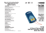
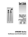
M5156-0612-P16PIP_awb 6/20/12 5:06 PM Page cov-1
®
User’s Guide
Shop online at
omega.com ®
e-mail: [email protected]
For latest product manuals:
omegamanual.info
MADE IN CHINA
P16PIP
Pipe and Duct Inspection
Probe and Reel Set
M5156-0612-P16PIP_awb 6/20/12 5:06 PM Page cov-2
®
OMEGAnet ® On-Line Service
omega.com
Internet e-mail
[email protected]
Servicing North America:
U.S.A.: ISO 9001 Certified
OMEGA Engineering, Inc.,
One Omega Drive, P.O. Box 4047
Stamford, CT 06907-0047
Toll-Free: 1-800-826-6342 Tel: (203) 359-1660
FAX: (203) 359-7700 e-mail: [email protected]
Canada:
976 Bergar
Laval (Quebec), H7L 5A1 Canada
Toll-Free: 1-800-826-6342 TEL: (514) 856-6928
FAX: (514) 856-6886 e-mail: [email protected]
For immediate technical or application assistance:
U.S.A. and Canada:
Sales Service: 1-800-826-6342/1-800-TC-OMEGA®
Customer Service: 1-800-622-2378/1-800-622-BEST ®
Engineering Service: 1-800-872-9436/1-800-USA-WHEN®
Mexico/Latin Ameica:
En Español: 001 (203) 359-7803
FAX: 001 (203) 359-7807
[email protected]
e-mail: [email protected]
Servicing Europe:
Benelux:
Managed by the United Kingdom Office
Toll-Free: 0800 099 3344 TEL: +31 20 347 21 21
FAX: +31 20 643 46 4
e-mail: [email protected]
Czech Republic:
Frystatska 184
733 01 Karviná, Czech Republic
Toll-Free: 0800-1-66342 TEL: +420-59-6311899
FAX: +420-59-6311114 e-mail: [email protected]
France:
Managed by the United Kingdom Office
Toll-Free: 0800 466 342 TEL: +33 (0) 161 37 29 00
FAX: +33 (0) 130 57 54 27
e-mail: [email protected]
Germany/Austria:
Daimlerstrasse 26
D-75392 Deckenpfronn, Germany
Toll-Free: 0800 6397678 TEL: +49 (0) 7056 9398-0
FAX: +49 (0) 7056 9398-29
e-mail: [email protected]
United Kingdom:
ISO 9001 Certified
OMEGA Engineering Ltd.
One Omega Drive
River Bend Technology Centre
Northbank
Irlam, Manchester M44 5BD
United Kingdom
Toll-Free: 0800-488-488
TEL: +44 (0) 161 777-6611
FAX: +44 (0) 161 777-6622
e-mail: [email protected]
It is the policy of OMEGA Engineering, Inc. to comply with all worldwide safety and EMC/EMI regulations that apply. OMEGA
is constantly pursuing certification of its products to the European New Approach Directives. OMEGA will add the CE mark
to every appropriate device upon certification.
The information contained in this document is believed to be correct, but OMEGA accepts no liability for any errors it
contains, and reserves the right to alter specifications without notice.
WARNING: These products are not designed for use in, and should not be used for, human applications.
M5156-0612-P16PIP_awb 6/20/12 5:06 PM Page i
PIPE & DUCT INSPECTION
PROBE & REEL SET
USER’S MANUAL
P16PIP
Please read this manual carefully and thoroughly before using this product.
M5156-0612-P16PIP_awb 6/20/12 5:06 PM Page ii
TABLE OF CONTENTS
Introduction . . . . . . . . . . . . . . . . . . . . . . . . . . . . . . . . . . . . 1
Key Features . . . . . . . . . . . . . . . . . . . . . . . . . . . . . . . . 1 – 2
Safety Instructions . . . . . . . . . . . . . . . . . . . . . . . . . . . . . . . 2
What’s in the Case . . . . . . . . . . . . . . . . . . . . . . . . . . . . . . . 2
Product Overview . . . . . . . . . . . . . . . . . . . . . . . . . . . . . 3 – 4
Setup Instructions . . . . . . . . . . . . . . . . . . . . . . . . . . . . 4 – 5
Attach Borescope . . . . . . . . . . . . . . . . . . . . . . . . 4 – 5
Operating Instructions. . . . . . . . . . . . . . . . . . . . . . . . . . 6 – 8
Attaching an Accessory . . . . . . . . . . . . . . . . . . . . 6 – 8
Operating & Maintenance Tips . . . . . . . . . . . . . . . . . . 9 – 10
Specifications . . . . . . . . . . . . . . . . . . . . . . . . . . . . . . . . . . 11
ii
M5156-0612-P16PIP_awb 6/20/12 5:06 PM Page 1
INTRODUCTION
Thank you for purchasing the Omega Engineering, Inc. P16PIP Pipe & Duct
Inspection Probe & Reel Set. Please read this manual carefully and thoroughly
before using the product.
The P16PIP is a probe and reel set that—when attached to a video borescope
inspection system from General—allows plumbers to visually inspect the
interior of water and sewer pipes carrying running water, and HVAC specialists
to visually inspect the interior of ducts. In both applications, inspections can be
documented with video clips and still photos to provide evidence and the
location of blockages or cracks.
The probe and reel set is compatible with the:
• HHB1600 and HHB1800 Recording Video Borescope Inspection Systems
KEY FEATURES
• Ideal for examining the interior of water pipes, sewer pipes, and HVAC
ducts. Especially tailored for 2, 4 and 6 in. I.D. pipes by included probe
centering accessories
• 72 ft. (22m) long probe with 1.1 in. (28mm) diameter camera head
• Eight super-bright white LEDs give probe 640 x 480 pixel (VGA) resolution;
superior optics yield excellent depth of field of 0.4 in. (10mm) to infinity
• Probe is water-tight to IP68 standard (depth of 33 ft./10m) and flexible
enough to make two or more (depending on conditions inside the pipe)
90° bends in a 1.6 in. (40mm) I.D. pipe
• Stainless steel camera head is immune to bathroom toilet cleaner, pipe
and drain cleaning chemicals, gasoline, brake/transmission fluid and
machine oil
• Steel probe reel is sturdy and dust-tight to IP6X standard, works vertically
or horizontally, and has bracket for H16 (HHB1600) console
1
M5156-0612-P16PIP_awb 6/20/12 5:06 PM Page 2
SAFETY INSTRUCTIONS
CAUTION!
Do not use the P16PIP to inspect ducts
known or suspected to contain live electric wiring
WHAT’S IN THE CASE
The P16PIP Pipe & Duct Inspection Probe & Reel Set comes in a hard plastic
protective case along with this user’s manual and the following accessories:
• One spherical metal ring for centering the probe in 2 in. I.D. pipes
• One brush set for centering the probe in 4 in. I.D. pipes
• One brush set for centering the probe in 6 in. I.D. pipes
• A 5/64-in. Allen wrench for attaching the 2 in. probe centering ring
• A plastic bag containing five spare 5/64-in. Allen screws
2
M5156-0612-P16PIP_awb 6/20/12 5:06 PM Page 3
PRODUCT OVERVIEW
Fig. 1 shows the key components of the P16PIP. Fig. 2 details the anatomy of
the camera-tipped end of the probe. Familiarize yourself with the names and
positions of these components before moving on to the Setup and Operating
Instructions.
Fig. 1. The key components of the P16PIP
Handle
Borescope
console holder
Reel frame
Coiled probe
Camera head
Probe guide/camera
head stopper
Reel stopper
Probe connector
(to borescope console
or handle/controller)
3
M5156-0612-P16PIP_awb 6/20/12 5:06 PM Page 4
Fig. 2. Structures
near the
camera-tipped
end of the probe
Camera head
Accessory mounting ring
Rubber probe cover
Metal coil
spring sleeve
Joint ball
Probe
SETUP INSTRUCTIONS
ATTACH BORESCOPE
The P16PIP is compatible with the following systems and components from
General:
• The HHB1600 and HB1800 Recording Video Borescope Inspection Systems
To attach the probe & reel set to the HHB1600 or to the HHB1800
handle/controller, first remove the red protective cap from the Probe
connector (see bottom of Fig. 1). Then pull back the metal collar of the
4
M5156-0612-P16PIP_awb 6/20/12 5:06 PM Page 5
connector to expose the alignment key with a red dot. Keeping the collar
pulled back, align this dot with the red dot on the connector of your
borescope console or handle/controller and push the two connectors
together. To secure the connection, release the collar and turn it clockwise
until tight. The following figure shows the final attachment step for the
(HHB1600) Console.
At the top of the P16PIP is a metal bracket designed to securely hold the
(HHB1600) console. If you are using the probe with a HHB1800 system, General
suggests not mounting the system’s transmitting handle/controller or receiving
console. Both components can be placed anywhere convenient—as long as it
is dry. Neither component is waterproof
or water-resistant.
5
M5156-0612-P16PIP_awb 6/20/12 5:06 PM Page 6
OPERATING INSTRUCTIONS
Before inspecting a pipe, determine its inner diameter. Then determine whether
that diameter matches the diameter of any of the three included probecentering accessories: 2, 4 or 6 inches. If your pipe is one of these three sizes,
attaching the correct accessory will keep the camera head in the center of the
pipe as you push the probe forward. A centered probe will be easier to push
forward and produce higher-quality videos and photos as well.
If the inner diameter of your pipe is not 2, 4 or 6 in., you can still use the probe
to good effect without the benefit of a probe-centering accessory. You may have
to exert a bit more effort to keep the camera head from getting hung up on the
pipe’s sidewalls as you push the probe forward. That is more likely if you use
the probe to inspect large pipes or rectangular ducts. In such situations, friction
will often cause the camera head to “tuck under” the probe as you push it
forward, producing a rear-facing dynamic view of the pipe’s interior. When you
begin to reel in the probe, however, the metal coil spring sleeve (see Fig. 1) will
free the camera head and point it forward. Videos and photos captured during
this “return” trip can be just as valuable as forward-facing evidence.
ATTACHING AN ACCESSORY
Before attaching any of the three
probe-centering accessories to the
probe, “play out” a few feet of the
probe from the reel. To do so, first
“unlock” the reel by separating
(opening) the Velcro closure called
the Reel stopper (see Fig. 1 and
figure at right).
6
M5156-0612-P16PIP_awb 6/20/12 5:06 PM Page 7
Once the reel is free to move, grab
the probe below the camera head
and begin pulling it horizontally,
rather than vertically, as shown at
right.
Extract just enough probe for the
Joint ball to pass the Probe
guide/camera head stopper (see
Fig. 1). Then—if this is the first use
of the P16PIP or its first use in
months—pull and push the end of
the probe back and forth a few
times (see figure at right) to reduce
any friction binding the reel’s
stationary and moving parts.
Once you have played out a few
feet of probe, lock the reel by
fastening the Velcro closure around
the reel frame, as shown below.
✓
7
M5156-0612-P16PIP_awb 6/20/12 5:06 PM Page 8
You can now attach the 2 in. spherical
ring, the 4 in. brush set or the 6 in.
brush set to the probe tip. To attach
the ring, slide its slightly larger open
end over the camera head (it fits only
one way) until the head protrudes about
1/8 in. past the ring’s other opening. In
this position, the ring’s Allen set screw
will line up with the Accessory mounting ring of the camera head (see Fig. 2).
Secure the ring to the head by using the included Allen wrench to tighten the
screw, as shown at right.
To attach either probe-centering brush set, identify the end with three set
screws. Passing the camera head through the other end first, slide the probe
through the brush set until the camera head protrudes 1/8 in. past the end with
the set screws (see figures below). In this position, the three set screws will line
up with the head’s Accessory mounting ring. Secure the brush set to the head
by hand-tightening the screws.
Screw holes
8
M5156-0612-P16PIP_awb 6/20/12 5:06 PM Page 9
OPERATING & MAINTENANCE TIPS
The reel operates equally well in a horizontal or vertical position.
The bracket for the (HHB1600) borescope console at the top of the P16PIP has
a flexible-obedient stem that allows the console’s screen to be angled to
a comfortable viewing position. DO NOT BEND this stem at an angle greater
than 90° (see figures at right below).
Before attempting to wind the
probe back onto the reel,
remember to “unlock” the reel by
undoing the Reel stopper (see
Fig. 1). The most effective way to
rewind the probe is to push it onto
the reel through the bars of the
Probe guide (see Fig. 1) horizontally
90°
from a distance of about 12 inches.
Continue pushing until the Joint
ball has passed through the Probe
guide. Stop when the camera
head meets the Camera head stopper (see figure at right below).
✓
12 in.
9
M5156-0612-P16PIP_awb 6/20/12 5:06 PM Page 10
Before cleaning the P16PIP, disconnect the (HHB1600) console from the probe,
remove the console from the mounting bracket and cover the probe connector
with the red protective cap, as shown above.
All parts of the probe and reel can be hosed down or cleaned with a cloth and
water or a mild solvent. After cleaning, allow fluid to drain from the unit for at
least five minutes. Then dry the unit carefully with a second cloth before
returning it and any accessories to the plastic case.
Note: All compatible consoles and probe controllers are NOT waterproof.
Be sure to disconnect your borescope and move it out of the way before
washing the P16PIP.
10
M5156-0612-P16PIP_awb 6/20/12 5:06 PM Page 11
SPECIFICATIONS
PROBE & CAMERA
Camera Head Diameter
1.1 in. (28mm)
Probe Diameter
0.23 in. (6mm)
Probe Length
72 ft. (22m)
Probe Material
Fiberglass
Camera Light Source
8 white LEDs
Camera Depth of Field
0.4 in. (10mm) to infinity
Camera Field of View
150.8° (diagonal)
Waterproof Depth (IP68)
50 ft. (10m)
Operating Temperature
14° to 158°F (-10° to 70°C)
Weight
4.9 lb. (2.2kg)
REEL
Frame Diameter
11.8 in. (300mm)
Dust and Water Resistance
To IP65 standard
Operating Temperature
14° to 158°F (-10° to 70°C)
Weight
6.6 lb. (3kg)
11
M5156-0612-P16PIP_awb 6/20/12 5:06 PM Page 12
NOTES:
12
M5156-0612-P16PIP_awb 6/20/12 5:06 PM Page 13
WARRANTY/ DISCLAIMER
OMEGA ENGINEERING, INC. warrants this unit to be free of defects in materials and workmanship for a period
of 13 months from date of purchase. OMEGA’s Warranty adds an additional one (1) month grace period to
the normal one (1) year product warranty to cover handling and shipping time. This ensures that OMEGA’s
customers receive maximum coverage on each product.
If the unit malfunctions, it must be returned to the factory for evaluation. OMEGA’s Customer Service Department will issue an Authorized Return (AR) number immediately upon phone or written request. Upon examination by OMEGA, if the unit is found to be defective, it will be repaired or replaced at no charge. OMEGA’s
WARRANTY does not apply to defects resulting from any action of the purchaser, including but not limited to
mishandling, improper interfacing, operation outside of design limits, improper repair, or unauthorized modification. This WARRANTY is VOID if the unit shows evidence of having been tampered with or shows evidence
of having been damaged as a result of excessive corrosion; or current, heat, moisture or vibration; improper
specification; misapplication; misuse or other operating conditions outside of OMEGA’s control. Components
in which wear is not warranted, include but are not limited to contact points, fuses, and triacs.
OMEGA is pleased to offer suggestions on the use of its various products. However, OMEGA
neither assumes responsibility for any omissions or errors nor assumes liability for any
damages that result from the use of its products in accordance with information provided by
OMEGA, either verbal or written. OMEGA warrants only that the parts manufactured by the
company will be as specified and free of defects. OMEGA MAKES NO OTHER WARRANTIES OR
REPRESENTATIONS OF ANY KIND WHATSOEVER, EXPRESSED OR IMPLIED, EXCEPT THAT OF
TITLE, AND ALL IMPLIED WARRANTIES INCLUDING ANY WARRANTY OF MERCHANTABILITY
AND FITNESS FOR A PARTICULAR PURPOSE ARE HEREBY DISCLAIMED. LIMITATION OF
LIABILITY: The remedies of purchaser set forth herein are exclusive, and the total liability of
OMEGA with respect to this order, whether based on contract, warranty, negligence,
indemnification, strict liability or otherwise, shall not exceed the purchase price of the
component upon which liability is based. In no event shall OMEGA be liable for consequential,
incidental or special damages.
CONDITIONS: Equipment sold by OMEGA is not intended to be used, nor shall it be used: (1) as a “Basic
Component” under 10 CFR 21 (NRC), used in or with any nuclear installation or activity; or (2) in medical
applications or used on humans. Should any Product(s) be used in or with any nuclear installation or
activity, medical application, used on humans, or misused in any way, OMEGA assumes no responsibility as
set forth in our basic WARRANTY/ DISCLAIMER language, and, additionally, purchaser will indemnify
OMEGA and hold OMEGA harmless from any liability or damage whatsoever arising out of the use of the
Product(s) in such a manner.
RETURN REQUESTS / INQUIRIES
Direct all warranty and repair requests/inquiries to the OMEGA Customer Service Department. BEFORE RETURNING ANY PRODUCT(S) TO OMEGA, PURCHASER MUST OBTAIN AN AUTHORIZED RETURN (AR) NUMBER
FROM OMEGA’S CUSTOMER SERVICE DEPARTMENT (IN ORDER TO AVOID PROCESSING DELAYS). The assigned AR number should then be marked on the outside of the return package and on any correspondence.
The purchaser is responsible for shipping charges, freight, insurance and proper packaging to prevent breakage in
transit.
FOR WARRANTY RETURNS, please have the
following information available BEFORE contacting
OMEGA:
1. Purchase Order number under which the product
was PURCHASED,
2. Model and serial number of the product under
warranty, and
3. Repair instructions and/or specific problems
relative to the product.
FOR NON-WARRANTY REPAIRS, consult OMEGA
for current repair charges. Have the following information available BEFORE contacting OMEGA:
1. Purchase Order number to cover the COST
of the repair,
2. Model and serial number of the product, and
3. Repair instructions and/or specific problems
relative to the product.
OMEGA’s policy is to make running changes, not model changes, whenever an improvement is possible. This affords our
customers the latest in technology and engineering.
OMEGA is a registered trademark of OMEGA ENGINEERING, INC.
© Copyright 2012 OMEGA ENGINEERING, INC. All rights reserved. This document may not be copied, photocopied, reproduced,
translated, or reduced to any electronic medium or machine-readable form, in whole or in part, without the prior written consent of
OMEGA ENGINEERING, INC.
M5156-0612-P16PIP_awb 6/20/12 5:06 PM Page 14
Where Do I Find Everything I Need for
Process Measurement and Control?
OMEGA…Of Course!
Shop online at omega.com sm
TEMPERATURE
DATA ACQUISITION
䡺
⻬ Thermocouple, RTD & Thermistor
Probes, Connectors, Panels & Assemblies
䡺
⻬ Wire: Thermocouple, RTD & Thermistor
䡺
⻬ Calibrators & Ice Point References
䡺
⻬ Recorders, Controllers & Process
Monitors
䡺
⻬ Infrared Pyrometers
䡺
⻬ Data Acquisition & Engineering
Software
䡺
⻬ Communications-Based Acquisition
Systems
䡺
⻬ Plug-in Cards for Apple, IBM &
Compatibles
䡺
⻬ Data Logging Systems
䡺
⻬ Recorders, Printers & Plotters
PRESSURE, STRAIN AND FORCE
䡺
⻬ Transducers & Strain Gages
䡺
⻬ Load Cells & Pressure Gages
䡺
⻬ Displacement Transducers
䡺
⻬ Instrumentation & Accessories
FLOW/LEVEL
䡺
⻬ Rotameters, Gas Mass Flowmeters &
Flow Computers
䡺
⻬ Air Velocity Indicators
䡺
⻬ Turbine/Paddlewheel Systems
䡺
⻬ Totalizers & Batch Controllers
pH/CONDUCTIVITY
䡺
⻬ pH Electrodes, Testers & Accessories
䡺
⻬ Benchtop/Laboratory Meters
䡺
⻬ Controllers, Calibrators, Simulators &
Pumps
䡺
⻬ Industrial pH & Conductivity Equipment
HEATERS
䡺
⻬ Heating Cable
䡺
⻬ Cartridge & Strip Heaters
䡺
⻬ Immersion & Band Heaters
䡺
⻬ Flexible Heaters
䡺
⻬ Laboratory Heaters
ENVIRONMENTAL
MONITORING AND CONTROL
䡺
⻬ Metering & Control Instrumentation
䡺
⻬ Refractometers
䡺
⻬ Pumps & Tubing
䡺
⻬ Air, Soil & Water Monitors
䡺
⻬ Industrial Water & Wastewater
Treatment
䡺
⻬ pH, Conductivity & Dissolved Oxygen
Instruments
M5156/0612