1
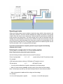
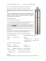
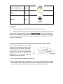
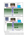
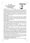
Installation Instructions for Solar Pumps
USER MANUAL FOR SPS, SPC, SPSC
SPQB, SPGJ SERIES SOLAR PUMPS
AND PUMP CONTROLLERS
www.icmsa.co.za
PUMP SPECIFICATIONS
Pump Model
voltage
(V)
Power
(W)
Max Flow
(M3/H)
Max
Head
(M)
Outlet
BSP
(IN)
3SPS1.0/30-D24/80
24
80
1
30
0.75"
3SPS1.3/50-D24/140
24
140
1.3
50
0.75"
3SPS1.8/80-D24/210
24
210
1.8
80
0.75"
3SPS1.8/100-D36/270
36
270
1.8
100
0.75"
3SPS1.8/120-D36/500
36
500
1.8
120
0.75"
3SPS2.3/140-D48/750
48
750
2.3
140
0.75"
3SPS2.3/160-D72/1000
72
1000
2.3
160
0.75"
3SPS2.3/180-D110/1300
110
1300
2.3
180
0.75"
4SPS3/60-D36/500
36
500
3
60
1"
4SPS3.6/80-D48/750
48
750
3.6
80
1"
4SPS4/100-D72/1000
72
1000
4
100
1"
4SPS4.2/120-D110/1300
110
1300
4.2
120
1"
Diameter
& length
(MM)
76*400
76*460
100*480
100*550
3SPC2.6/32-D24/300
24
300
2.6
32
1"
76*620
3SPC2.8/52-D36/500
36
500
2.8
52
1"
76*820
3SPC3.0/85-D48/750
48
750
3
85
1"
76*940
3SPC3.2/106-D72/1000
72
1000
3.2
106
1"
76*1060
4SPC5.0/28-D24/250
24
250
5
28
1.25"
100*540
4SPC5.5/38-D36/400
36
400
5.5
38
1.25"
100*650
4SPC5.5/58-D48/750
48
750
5.5
58
1.25"
100*680
4SPC6.0/72-D72/1000
72
1000
6
72
1.25"
100*740
4SPC10/30-D48/750
48
750
10
30
1.5"
100*540
4SPC10/44-D72/1000
72
1000
10
44
1.5"
100*650
4SPC10/57-D110/1300
110
1300
10
57
1.5"
100*680
Pump Model
voltage
(V)
Power
(W)
Max Flow
(M3/H)
Max
Head
(M)
Outlet
BSP
(IN)
Diameter
& length
(MM)
4SPSC5.0/28-D24/250
24
250
5
28
1.25"
100*540
4SPSC5.5/38-D36/400
36
400
5.5
38
1.25"
100*650
4SPSC5.5/58-D48/750
48
750
5.5
58
1.25"
100*680
4SPSC6.0/72-D72/1000
72
1000
6
72
1.25"
100*740
4SPSC6.5/98-D110/1300
110
1300
6.5
98
1.25"
100*880
4SPSC10/30-D48/750
48
750
10
30
1.5"
100*540
4SPSC10/44-D72/1000
72
1000
10
44
1.5"
100*650
4SPSC10/57-D110/1300
110
1300
10
57
1.5"
100*680
4SPSC15/21-D72/1000
72
1000
15
21
2"
100*540
4SPSC15/28-D110/1300
110
1300
15
28
2"
100*620
4SPSC23/21-D110/1300
110
1300
23
21
3"
125*700
4SPSC28/13-D110/1300
110
1300
28
13
3"
125*710
6SPSC46/7-D110/1300
110
1300
46
7
4"
125*690
Operating principle
Solar photovoltaic panels convert sunlight to electrical energy which is then passed to the
solar pump controller. The solar controller stabilises the voltage and creates a three phase
output to drive the electric motor of the pump. If backup batteries (optional) are available the
pump controller can charge them. The stored energy can be used at a later date when the
sunlight may not be adequate to drive the pump. Sensors are also connected to the controller
and can be used to protect the pump from running dry, as well as to automatically turn the
pump off when a water tank is full. The system can be remote from traditional power sources
and fully automatic, with no on-going electricity charges.
If you have not purchased a complete system from your supplier the following
formulae will be useful:
Selecting the components for the pumping system
Solar PV panel (solar photovoltaic panel) selection
Use the following formula to select the correct solar PV panel(s):
Power of pump (watts)
x 1.3 ~ 1.6
= power rating of solar PV panel(s) in watts
For example:
A 300 watt pump needs a minimum of 390 watts of PV panels to drive it:
300 watt pump
x 1.3
= 390 watt PV panel
• You may need combinations of panels, especially for the larger pumps.
• When you have panels in parallel, add the current of the panels and the wattage.
Note: If connecting in parallel you will need Schottky Diodes in series with each panel.
• When using panels in series add the voltage and the wattage.
For example:
2 x 12 volt 100 watt panels in parallel
become a 12 volt 200 watt system
2 x 12 volt 100 watt panels in series
become a 24 volt 200 watt system
Note: Your pump supplier will be able to help you with panel selection
The controller will already be matched to the pump by your supplier.
Battery selection if you want to pump when there is not enough
sun
If you want to add batteries please note that you will need an additional solar
charge controller (not supplied in the kit) and you will need to double the
number of PV panels. The extra PV panels are required to charge the
batteries while the pump is pumping.
The cheapest option is to:
a) try to fill an elevated header tank or
b) if you have no elevation locate the tank near a utility power supply so you
can pump water from the tank using a mains powered pump.
You must use deep cycle batteries, not car batteries. Deep cycle batteries
are designed to take much lower continual discharges than regular car
batteries. Deep cycle batteries normally have an ’amp hour’ rating shown as
AH, e.g. 100AH. Use the following formulas to calculate battery size required
for backup.
Please note that even with a deep cycle battery, discharging it to a low level
will shorten its life. This is why we use 60% as a discharge level.
Use the following formulae to select the correct battery or batteries:
Current drawn by the pump
= pump power divided by the voltage
300 watts
= 25 amps
divided by 12 volts
100 AH
divided 25 amps x 0.6
of backup with the
discharged to 60%
= 2.4 hours
battery being
In the case of a 24 volt 300 watt pump:
300 watts
divided by 24
= 12.5 amps
2 x 100AH 12volt batteries in series
= 100 AH at 24 volts
100AH
4.8 hours of backup
divided by 12.5 amps x 0.6
•
Batteries in parallel:
add the AH, voltage stays the same.
•
Batteries in series:
add the voltage, AH stays the same.
Question:
I want to have backup for 8 hours with a 300 watt 24 volt pump. How many AH do I need?
Answer:
300 watts divided by 24 volts = 12.5 amps.
8 hours divided 0.6 x 12.5 amps = 166AH (2 x 166 AH 12volt batteries in series)
Parts List
Solar pump
1pc
Controller
1pc
Impeller
1pc
Cable Connector
4pcs
OR
or
Water Level Sensor
4pcs
Rope
1pc
Manual
1pc
Installation
1.
Open the package and check that all the parts have been supplied.
2.
Before you start wiring, ensure that the control box switch is in the off position. The
pump needs to be submersed in water for at least 15 minutes before power is applied to
it. Water is the lubrication for the pump and if it is not ’preconditioned‘ properly the bearings
will not be adequately lubricated. This will result in premature wear and failure of the pump
and will void the warranty.
Connecting a longer cable to the pump (cable must be at least 1.5mm2 section)
Use the parts contained in the cable
connector kit to connect a longer supply wire
to the pump. If you don’t have a heat gun to
shrink the tube, the barrel of your soldering
iron will do, or you can use a butane torch
(but with great care so you don’t melt the
insulation or set it on fire). Bare the
insulation back as shown above.
1. Lay out the components needed to make the join.
2. Put the large diameter piece of heat-shrink over the main cable and then the smaller
diameter pieces over the individual wires. Keep the heat-shrink back away from the joints
as you solder them. Any heat transfer will prematurely shrink the heat-shrink.
3. and 4. Slide the small heat-shrink over
the soldered joints and heat using a
heat gun or alternative heat source to
shrink the sleeve down over the wires.
5. Slide the large diameter heat-shrink
over the completed joint and shrink to
it.
IMPORTANT: Place the pump in water
before you start wiring the controller box.
This will allow the pump to go through the
pre-conditioning required. Do not put the
pump in its final position until you have
tested it, unless it is easy to see and
remove.
Wiring the control box
1. Wire the pump, panels and optional battery to the control box as per the wiring diagram
below. When wiring the pump do not worry about the wiring orientation, just connect the
pump wires to the controller making sure they do not touch each other. You will test the
system later. If you find that the wiring is incorrect the pump will run backwards and you
will only have to swap over two wires to get it running correctly. You have a 50:50 chance
of getting it correct the first time.
If you are intending to use a battery use the bottom wiring diagram. Make sure the polarity
is correct - plus to plus, minus to minus. Charge controllers generally have the following
connections - Battery, Panel and Load either written or in pictorial form. The pump
controller solar PV input is connected to the load terminals of the charge controller. As a
safety margin we recommend that the charge controller be able to supply at least 1.5
times the pump requirements.
Basic formula:
Load (amps) = pump wattage / voltage
= amps.
Amps x 1.5
= charge control load, e.g. a 300 watt 24 volt pump. 300/24 = 15 amps.
15A x 1.5
= 22.5 amps.
The charge controller must be able to supply 22.5 amps to the load at 24 volts.
Caution: When wiring a battery be very careful not to reverse or short the terminals. While
the voltage is low the current capability is in the order of hundreds, if not thousands of amps
and you can do serious damage. We advise you to remove all metal wrist bands or watches
before you start. A short across a metal watch strap will result in it glowing red hot in seconds,
causing very serious burns. Solar PV panels, when connected together, can also produce a
lot of energy so caution must also be exercised here as well. Laying a dark cloth over the
panels to shade them is a good precaution to reduce the power output.
2. It is important that the water sensors are connected properly. The water low (WH) and
water common (WC) are very important because they protect the pump from running dry.
Do not link out WH under any circumstances
(the only exception is for troubleshooting). The
sensors The sensor terminals TC and TH can be
left disconnected if you are not using a header
tank or don’t care if the water flows out on the
ground once the tank is full. The sensor probes
are all the same – they just have different
coloured wiring. For clarity we recommend you
use the probes with white wires as the common
probes (WC and TC) and the other colours for
WH and TH.
Testing the pump
The pump must be under water at all times and should have been pre-conditioned for at least
15 minutes. Do not attempt to test the pump even for a moment without it being submerged
or permanent damage will occur. You will need a large container so the pump does not
pump it dry in seconds.
The WH and WC sensors must be in the water. TH also needs to be out of water or not
connected.
1. The PV panels need to be in full sun. Turn on the control switch. The pump has a ‘soft
start function’ and will start after 6 seconds and then spin up to full speed in the next 6
seconds. If the wiring is correct the pump will restart and the pump will run continuously.
If the pump does not pump much water it is possible the wiring of the pump is incorrect
and it is running backwards. To correct this, switch off the control box and reverse the
wires to terminals 1 and 2. Switch the controller on again and the pump should now be
working correctly after self-diagnostics.
2. Test the sensors one at a time. Pull the sensor connected to WH out of the water. The
pump should stop immediately. Put the sensor back under water and the pump should
start. To test TH and TC start the pump with TH and TC out of the water. Put TH and TC
in water. The pump should stop. Pull the TH sensor out of the water and the pump should
start again after 3 minutes.
Installing the pump
1. Attach a durable rope or stainless steel cable to the top of the pump using the mounting
hole. Make sure the rope or cable is longer than the depth at which you want to install the
pump. This is used to raise and lower the pump. Never use the power cable to do this.
2. Very important! Attach the WH sensor with a tie wrap to the pump cable so it will be at
least 0.5 metres above the pump body when it is installed, the higher the better. The WC
sensor needs to be placed below the WH sensor.
3. Connect the water line and lower the pump into the bore hole, well, stream lake etc. Please
note the pump must be operated vertically so the bearings have no excess side thrust on
them and the water should be clean with no corrosive materials e.g. sand in it. The pump
must be at the correct depth. Do not put the pump any deeper than 20 metres in the water.
Depending on the water source the level can drop when water is drawn off so the sensors
need to be placed appropriately to account for this, otherwise it will be stopping and
starting.
Dos and don’ts
Do keep the pump under water at all times when operating.
Do be careful with wiring.
Do remove the pump if not using it for a long time and wipe the screw and body. Wipe with
vegetable oil.
Do make sure the pump has adequate water around it during pumping. If the sensors are
activated there will be at least a 3 minute delay between pumping sessions.
Do put your solar PV panels in a sunny position facing true north (southern hemisphere) or
true south (northern hemisphere). If the panel angle is fixed then an angle equal to your
latitude will be a good compromise.
Don’t run the pump out of the water, even momentarily. It will void the warranty.
Don’t bypass the WH sensor except to troubleshoot.
Don’t adjust the regulation bolt in the base of the pump. It is factory set. It will void the
warranty.
Don’t use the pump in dirty water. Premature wear will not be covered by warranty.
Troubleshooting using the pump controller indicator lights
Power light: If everything is operating properly this
will be green. If it is not green then the voltage may be
too low (not enough sunlight), the pump is drawing too
much current (head too high) or the controller
temperature is too high (put it in a cool position with
plenty of air circulation).
MPPT light: This is normally green and if the pump is
operating properly it will stay green. If it is not green
then the voltage may be too low (not enough sunlight),
the pump is drawing too much current (head too high),
the controller temperature is too high (put it in a cool
position with plenty of air circulation), too much
current or the controller temperature is too high.
Well level light: If this lamp is off the water level in
the well has dropped below the sensor (WH) and it is
protecting the pump from running dry. Remedy: Lower
the pump deeper into the water so when the water is
drawn off the water level stays well above the
pump.
Tank light: If the light is red the tank is full so the pump will stop. If you have linked this out
it will always be off. If the light is off then the pump will pump provided there is enough
sunlight.
Limited 1 Year Warranty
1. The manufacturer extends only to the original consumer purchaser a limited
warranty against defects in material and workmanship for a period of three years
from the date of purchase. This warranty covers the pump, controller and sensors.
2. The manufacturer or authorized factory representative will repair, or at its option
replace any defective part or parts of the product free of charge. In the event of a
malfunction the purchaser must return the product to an authorized dealer/agent at
their expense. The warranty is limited to the repair or replacement of the product
and the manufacturer or its dealers disclaim all liability for indirect and/or
consequential damages such as any installation charges.
3. The warranty does not apply when the equipment has not been installed as per the
instructions or damage has occurred through abuse, carelessness, improper
installation, accident of mishandling during shipment, connecting to an improper
voltage or it has been serviced by anyone other than an authorized factory
representative.
4. A purchase receipt or invoice for proof of purchase must be presented to claim
warranty.
5. All repairs not covered by warranty or outside the warranty period will be charged at
normal rates.