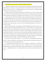
1
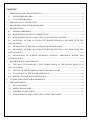
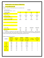
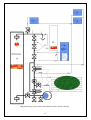
DOMESTIC SOLID FUEL BOILER STROPUVA INSTALLATION AND MAINTENANCE MANUAL CERTIFICATE NO. SPSC-672 CONTENT 1. DIMENSIONS AND CHARACTERISTICS.........................................................................................4 1.1 WOOD-FIRED BOILERS ..............................................................................................................4 1.2 COAL-FIRED BOILERS................................................................................................................5 2. DESCRIPTION OF A STRUCTURE ....................................................................................................6 3. TRANSPORTATION AND WAREHOUSING ....................................................................................7 4. BOILER FITTING .................................................................................................................................7 4.1. FIRE REQUIREMENTS ................................................................................................................8 4.2. REQUIREMENTS FOR THE CHIMNEY FLUE ..........................................................................8 4.3. REQUIREMENTS FOR CONNECTING TO THE HEATING SYSTEM ....................................9 4.4 MOUNTING PICTURE OF SOLID FUEL BOILER STROPUVA S40 NODE WITH THE LOST OF PARTS ....................................................................................................................................10 4.5. DESCRIPTION OF HEATING SYSTEM SCHEME OPERATION ..........................................12 4.6 MOUNTING PICTURE OF SOLID FUEL BOILER STROPUVA S40 NODE WITH THE LOST OF PARTS ....................................................................................................................................13 4.7. DESCRIPTION OF SCHEME OPERATION WITHOUT ADDITIONAL BOILER AND FLOOR HEATING ..................................................................................................................................15 5. BOILER BURNING AND KINDLING ...............................................................................................16 5.1. THE MOST ECONOMICALLY FUEL BURNS DOWN IN THE BOILER WHEN IT IS FULLY LOADED ...................................................................................................................................16 5.2. SETTING OF THE BI-THERMAL DRAUGHT REGULATOR ................................................18 5.3. EVALUATION OF THE BOILER OPERATION .......................................................................20 5.4. BOILER CLEANUP AND MAINTENANCE .............................................................................20 6. ACCIDENT PREVENTION REQUIREMENTS ................................................................................21 7. RISK ASSESSMENT ..........................................................................................................................22 7.1. HEAT HAZARDS ........................................................................................................................22 7.2. PRESSURE HAZARDS ...............................................................................................................23 7.3. POSSIBLE INTOXICATION .......................................................................................................23 7.4. REQUIREMENTS FOR CONNECTING OF ELECTRIC PARTS .............................................23 DEAR CUSTOMER, We are delighted that you have put your trust in us. We present the domestic solid fuel boiler, in the mouth of which the burning time of one load is measured in days. With one load of wood, peat and sawdust briquettes the boiler burns for about 30 hours and with coal, the burning time is about 7 days. Exceptional characteristics of the manufactured products, which prolong the burning time of the solid fuel boiler, are the distribution of air from the top and the solid fraction burning in the candle principle. Before installing and using it, we would ask that you read this Manual carefully and follow the Instruction closely, as this will guarantee better results when using the appliance. Keep this Instruction Manual in a safe place so that you can refer to it easily and thus abide by the guarantee conditions. You should keep the Guarantee Certificate or, where relevant, the technical datasheet, together with the Instruction Manuak for the duration of the useful life of the appliance. It has important technical information about the appliance. Solid fuel heating boilers STROPUVA (hereinafter referred to as “the boiler”) are intended for various premises/rooms where a central heating system is installed with radiators, heat water boiler for domestic purposes or floor coils or heaters, or all together for heating. The system can be both with natural and forced circulation, closed or opened. 1. DIMENSIONS AND CHARACTERISTICS 1.1 WOOD-FIRED BOILERS Table 1.1. Dimensions and characteristics for wood-fired boilers. Solid fuel: firewood logs, timber waste, sawdust briquettes. (Recommended moisture - ≤30%)* MODEL PARAMETRES S7 S10 S20 S40 Power (kW) 7 10 20 40 20-80 50-100 100-250 200-450 Fuel capacity (dm3) 150 200 350 500 Amount of firewood (kg) 15 25 50 80 Length of firewood (cm) 30-35 30-35 35-45 45-55 Water amount in the boiler (l) 26 34 45 58 Water temperature in the boiler (°C) 70 70 70 70 Heated area (m2) Coefficient of useful operation (%) 91,6 Flow of heated water (m3/h) 0,2 0,25 0,5 1,0 250x210 250x210 260x220 280x240 Height (mm) 1250 1900 1900/2100 1900/2100 Diameter (mm) 450 450 560 680 Mass (kg) 100 185 231 315 Dimension of load opening (mm) * - Firewood containing more than 30 % moisture shall not burn at all and if burn – shall not endure the required temperature, the burning shall be unstable. Combustion duration of fuel loading depend on its quality, outside and inside temperature, building quality and other factors. Table 1.2. Information for adjusters. Distance between Chimney floor and diameter MODEL chimney (mm) (mm) Distance Distance between between floor and floor and lower muff Ø upper muff Ø 32 (mm) 32 (mm) Pressure valve (bar) Water pressure no more than (bar) S7 1010 140 27.5 1187.5 1,5 2 S10 1430 160 12.5 1717.5 1,5 2 S20 1550 180 23.5 1936.5 1,5 2 S20 (1.9m) 1410 180 27.5 1727.5 1,5 2 S40 1550 200 38 1913 1,5 2 S40 (1.9 m) 1400 200 40 1710 1.5 2 1.2 COAL-FIRED BOILERS Table 1.3. Dimensions and characteristics for coal-fired boilers. Solid fuel: firewood logs, timber waste, sawdust and peat briquettes, coal. (Recommended moisture - ≤30%)* PARAMETRES MODEL S10 U S20 U S40 U 10 20 40 50-100 100-200 180-400 Fuel capacity (dm ) 200 350 500 Amount of coal (kg) Amount of firewood (kg) 75 25 130 50 220 80 Length of firewood (cm) 30-35 35-45 45-55 Water amount in the boiler (l) 34 45 58 Water temperature in the boiler (°C) 85 85 85 Power (kW) Heated area (m2) 3 Coefficient of useful operation (%) 91,6 Flow of heated water (m3/h) 0,25 0,5 1,0 250x210 260x220 280x240 Height (mm) 1900 1900/2100 1900/2100 Diameter (mm) 450 560 680 Mass (kg) 196 246 333 Dimension of load opening (mm) * - Firewood containing more than 30 % moisture shall not burn at all and if burn – shall not endure the required temperature, the burning shall be unstable. Combustion duration of fuel loading depend on its quality, outside and inside temperature, building quality and other factors. Table 1.4. Information for adjusters. Distance between Chimney floor and diameter MODEL chimney (mm) (mm) Distance Distance between between floor and floor and lower muff Ø upper muff Ø 32 (mm) 32 (mm) Pressure valve (bar) Water pressure no more than (bar) S10 U 1550 160 57.5 1737.5 1.5 2 S20 U 1695 160 57.5 1947.5 1.5 2 S20 U (1.9m) 1530 160 57.5 1747.5 1.5 2 S40 U 1675 180 57.5 1947.5 1.5 2 S40 U (1.9 m) 1520 180 57.5 1747.5 1.5 2 2. DESCRIPTION OF A STRUCTURE The boiler (see figure 2.1.) is a steel cylinder covered by a steel cylinder of a bigger diameter, a structure isinsulated. Bi-thermal draught regulator (2) with wooden stick (3) is at the front side of the boiler (see for details item No. 5.2.). Heated water is between the cylinders. A structure has openings for loading (8) of solid fuel (10), ash removal (11) and smoke extraction flue (5). There are also openings for water supply (14 - 15), thermometer (16) and pressure safety valve (17). Air heating compartment (4) for the improvement of combustion quality and heating transmission is mounted on the upper part of a combustion compartment. The boiler can be configured with grid bars and switching valve (6) for burning with peat or coal. There is a gap between a heating compartment and boiler walls through which smoke pours so that the heat would be better transmitted. A telescope air feeding pipe (7) fits into a compartment at the end of which the air distributor is fixed (9). 6 An opening for air injection and regulating valve (1) is at the upper part of a compartment. Upon request, a concrete bottom with an insulating band is configured with the boiler (18). Lift cable (12) with a ring of the air feeding mechanism is placed at the right side of the boiler in front of the door (a fixing hook (13). The purpose of the air distributor is to distribute correctly the air in the generation zones below and near the air distributor, at the combustion zone near and above the distributor. Air distributor leans upon the side firewood logs which do not get heated up to a high temperature. It is no allowed to move a distributor during the combustion: after moving the air distributor up and down, it turns and sinks deep into the combustion place and then the boiler operation is uneconomic, its parts worn out more. 3. TRANSPORTATION AND WAREHOUSING Boilers are allowed to be transported unfastened only in a horizontal position. If it does not rain, it is allowed to transport with an open transport, in other cases it must be transported with a covered transport. When transporting in a vertical position additional protection measures must be taken so that the boilers won„t fall and scratch. Boilers can be stored in dry premises free of chemical active agent steam. 4. BOILER FITTING The boiler is fitted in the premises corresponding to the state requirements established for the premises of boiler houses. Premises where a boiler will be fitted must be at least 215 m in height and with concrete flooring (at least in that place where the boiler will be erected). Premises must be made watertight and protected from heated residential rooms and would have a vertical ventilation channel and window or opening in the outside wall so that he air from outside would pass into the boiler and ventilation channel. Using a mirror examine the inside of the chimney flue through the chimney flue cleanup opening. The chimney flue must be clean. There must be no fittings nor bird nests and unsealed openings leading to cavity ceilings and adjacent mines. It is verified whether the chimney flue does not have openings or cracks in the outside through which the parasitic air can pass which will cool the chimney flue and reduce its draught. Cracks, openings and a place where the boiler is connected to the chimney flue must be sealed. If there are inner openings in the chimney flue leading to ceilings or adjacent mines/shafts and there is no possibility to repair them, an oval or cylinder insert of stainless steel must be fitted in. (Rectangular inserts are not reliable due to cracks formed in connection places due to temperature changes). The boiler is erected straight on concrete floor; any cracks between the floor and the boiler are sealed with heat resistant silicone or lime-cement solution with sand or other materials. The boiler can be erected on a concrete bottom intended for fitting with an insulation rope. 7 During carrying sometimes parts of the boiler get deformed therefore when it is fitted into the chimney flue and after closing all the doors and also the opening of the chimney flue cleanout opening, check the operation of the upper valve, its nestling against surface of the air intake opening and doors insulation using the flame of a candle or match. 4.1. FIRE REQUIREMENTS The boiler is erected on a non flammable base. Metal connection of the boiler near the chimney must be produced from metal not thinner than 1,5 mm and coated with heat insulation materials. The condition of the chimney flue must be checked once per month (by examining it during the day time through the cleanup opening with a mirror), in the event of necessity – clean it since soot and tars build up in the chimney flue can ignite, throw the sparks, cause fire hazard, overheat or damage the insert. Using branded chimney flues (of stainless steel or ceramic), study the users‟ manual and fulfill the requirements, cleaning periodicity in particular. When the chimney flue is cleaned up, a horizontal flue between the boiler and chimney flue must be cleaned up either. 4.2. REQUIREMENTS FOR THE CHIMNEY FLUE The cross-width of the chimney flue opening can be 10 percent less as it is specified in the main technical requirements but not bigger. The boiler requires an individual chimney flue; any other devices cannot be connected to it. So that the formed condensate in the chimney flue would not get into the boiler, a flue from the boiler to the chimney flue must be horizontal and not longer than 1.5 m and not shorter than 0.20 m, well sealed and insulated with a heat insulation material in the connection places. Flue and chimney flue is periodically cleaned up considering the mentioned above fire requirements. It is recommended: to fit in the chimney the insert of stainless steel; an orderly and correctly fitted insert protects the chimney against the effect of condensate or moister; an insert must not minimize significantly the cross section of the chimney opening; parts of the insert must be tightly interconnected (with stainless steel rivets); ash collector must be mounted below, collector must be mounted 15-20 cm below the flue connection to the chimney flue; then the flue can be easily cleaned up through it; the gap of the chimney between an insert and chimney walls, at least outside the chimney, fill with inflammable insulation materials. At the top a crack must be hermetically plastered and tin coated with a slope (from the opening to the chimney side); the chimney at the cold loft must be sealed with inflammable insulation materials. 8 4.3. REQUIREMENTS FOR CONNECTING TO THE HEATING SYSTEM It is allowed to fit in the boiler by qualified technicians who are aware of all requirements and who give guarantees on their job, and every time consults our boiler operating manual. Our product is not very similar to previous structures. Therefore what fits to other boilers does not fit to it. For instance, boilers where combustion runs below a firebox, it is recommended an intense return of the heated flow. It does not fir to our coiler. If up-to-date elements of heating systems in the connecting diagrams of other boilers are used very diversely and various and complicated connection diagrams are recommended we recommend only several simple, cheap and justified diagrams. During fitting procedure of supplement elements, please read the manufacturer requirements and follow them: 1. According to recommendations of thermal valve manufacturers, set pre-flow valves according to the instructions of the heating system design (if it is not the case, then at 1.5 or 1). 2. Do not exceed heat flow through the floor temperature with floor heating automatic elements (recommendations of manufacturers: 28 – 35ºC). 3. Upon fitting three-stage or four-stage mixing valves and a circular pump so that elements of the boiler and heating would not be shunted mount on a large ring of the house heating system. Preferably on a reversible flow pipe. 4. As it usually happens, do not shunt elements of the boiler and heating in parallel to a hot water heater connected to the boiler (a balance valve is required when connecting a hot water heater in parallel). 5. Maintain the temperature sufficient to a good boiler operation (70 † 85ºC). 6. Follow the recommendations of the chimney flue insert producer. 7. It is not allowed to fit the chimney flue closing valve. To reduce its draught, use our or other producers‟ self-intake air valves. 8. Take care of proper ventilation in a boiler room. 9. Every time when fitting our solid fuel boiler look at the technical certificate (useful additions and recommendations are possible). 9 4.4 MOUNTING PICTURE OF SOLID FUEL BOILER STROPUVA S40 NODE WITH THE LOST OF PARTS No. Plumbing detail Unit (s) 1 * - Pressure safty valve 1 2 Automatic air vent 1 3 Balance valve D15 1 4 Transition D25 – 15 3 5 Trident D25 11 6 Trident D25 – 15 2 7 Clutch D25 1 8 Nipple D25 18 9 Collapsible connector D25 SME 2 10 Bend D25 SME 3 11 Transition D32 – 25 2 12 Spherical valve D25 SME 3 13 Bend D25 2 14 Thermostatic valve DT25 1 15 Subjugation set of circulation pump 7 16 Circulation pump 1 17 Brass disk bolt D25 2 18 19 Release and complement valves D15 Three way valve for flow distribution D25 2 1 Fig. 4.1. Plumbing node. R - to/from radiator (s), F - to/from floor heating, B - to/from boiler, K2 - to/from other solid fuel boiler. Nodes for boilers S7, S10, S20 are collected from parts D20. Node for boiler S40 is collected from parts D25. ATTENTION: 1,5 bar pressure safety valve involves into the opening (17) (fig. 2.1.). Instead trident (5), use a bend D25 SME (10). 10 Fig. 4.2. Heating system scheme with additional boiler and floor heating. 11 4.5. DESCRIPTION OF HEATING SYSTEM SCHEME OPERATION The pump (P) pumps the water out of the heating elements and pushes it through the boiler into the heating elements (see figure 4.2.). Through balance faucet (bk l) the heated water flows into the nearest radiator, which can operate in a self-flowing manner to protect the boiler from overheating (radiator without a thermo valve) in case the power went off. Hereafter the heated water flows through the non solid fuel boiler 2k (if such is available), which turns on as the boiler 1k stops burning or turns off when the boiler 1k is supplying the hot water thanks to internal automatics. If the boiler 2k is available the bolt (3) is turned off, if it is not – the bolt is turned on. Hereafter the heated water flows through the water heater (B) and the bolt (3). If the heater input is of a sufficient diameter, the bolt (3) is turned off – as the water flows only through the heater, more water is heated. After it has heated the domestic water, the thermofication water flows into the ratiator systems and through the thermostatic valve (T2-20-50) if required and gets into the floor heating system. The thermostatic valve sensor opens the valve up if the water is colder than indicated (35°C) and closes it if the water is warmer. Thanks to the pump (P) the water abundantly circulates through the floor heating coil pipes (F) and also flows into the boiler through theflow distribution valve (T-3-20-50), which, due to the sensor, directs a part of the colder flow into the radiatior system as the returning flow is warmer that indicated (40°), maintaining a stable premise warmth even if no thermo valves are available and protecting the floor from overheating. (bk2) and (bk3) are the closure valves (not the faucet with spherical rotating closure) or more improved flow determination valves, through which the pump flow is distributed in such manner that it would be sufficient enough for floor heating and appropriate for the pump. Overall flow amount depends on the circulation pump and might be controled by switching the pump speed positions. If the system do not has floor heating T2, it is not necessary to install the thermostat during the summer. Creating a solid fuel boiler for heating boiler, radiator and floor manifold close and open the T2 from the unscrew the cap or removing the thermostat. A circulation pump with the power of 25 – 60 W is enough for a 10kW boiler, 40 - 80 W for a 20 kW boiler and 50 – 100 W for a 40 kW boiler. (bk1) - a balance faucet of a safety auto flow radiator, through which the flow is determined to make the radiator reversible pipe 40°C cooler than the infusion pipe. (7) - collapsible connectors – by releasing them the node may be reversed to another side of the boiler. 12 4.6 MOUNTING PICTURE OF SOLID FUEL BOILER STROPUVA S40 NODE WITH THE LOST OF PARTS No. Plumbing detail Unit (s) 1 * - Pressure safty valve 1 2 Automatic air vent 1 3 Balance valve D15 1 4 Transition D25 – 15 2 5 Trident D25 7 6 Trident D25 – 15 3 7 Clutch D25 1 8 Nipple D25 11 9 Collapsible connector D25 SME 2 10 Bend D25 SME 3 11 Transition D32 – 25 2 12 Spherical valve D25 SME 3 13 Bend D25 2 15 Subjugation set of circulation pump 7 16 Circulation pump 1 17 Brass disk bolt D25 1 14 18 19 Release and complement valves D15 Three way valve for flow distribution D25 2 1 Fig. 4.3. Plumbing node. R - to/from radiator (s), B - to/from the boiler. Nodes for boilers s7, s10, s20 are collected from parts D20. Node for boiler s40 is collected from parts D25. ATTENTION: 1,5 bar pressure safety valve involves into the opening (17) (fig. 2.1.). Instead trident (5), use a bend D25 SME (10). 13 Fig. 4.4. Heating system scheme without additional boiler and floor heating. 14 4.7. DESCRIPTION OF SCHEME OPERATION WITHOUT ADDITIONAL BOILER AND FLOOR HEATING The pump (P) pumps the water out of the heating elements and pushes it through the boiler into the heating elements (see figure 4.4.). Through balance faucet (bk l) the heated water flows into the nearest radiator, which can operate in a self-flowing manner to protect the boiler from overheating (radiator without a thermo valve) in case the power went off. Hereafter the heated water flows through the non solid fuel boiler 2k (if such is available), which turns on as the boiler 1k stops burning or turns off when the boiler 1k is supplying the hot water thanks to internal automatics. If the boiler 2k is available the bolt (3) is turned off, if it is not – the bolt is turned on. Hereafter the heated water flows through the water heater (B) and the bolt (3). If the heater input is of a sufficient diameter, the bolt (3) is turned off – as the water flows only through the heater, more water is heated. After the heating domestic water, thermofication water flows to the radiator system. Thanks to the pump (P) the water abundantly circulates through the flow distribution valve (T-320-50), which, due to the sensor, directs a part of the colder flow into the radiatior system as the returning flow is warmer that indicated (40°C), colder part of the flow refers to the radiator system, and maintained a stable indoor heat, even in the absence of thermovalves. A circulation pump with the power of 25 – 60 W is enough for a 10kW boiler, 40 - 80 W for a 20 kW boiler and 50 – 100 W for a 40 kW boiler. (bk-1) - a balance faucet of a safety auto flow radiator, through which the flow is determined to make the radiator reversible pipe 40°C cooler than the infusion pipe. (7) – collapsible connectors – by releasing them the node may be reversed to another side of the boiler. 15 5. BOILER BURNING AND KINDLING 5.1. THE MOST ECONOMICALLY FUEL BURNS DOWN IN THE BOILER WHEN IT IS FULLY LOADED Switching valve (6) when burning firewood logs must be lowered (see figure 5.1. A.), when coal is burning – it must be lift up (fig. 5.1. B). When loading fuel, the air distribution (9) must be lifted up; therefore take a ring at the cable end (12) hanging in the right above the firebox doors, pull down and put on a hook (13). Fig. 5.1. Switching valve inside the boiler. Use the air distributor (9) (see figure 5.2. firewood. A.) then Load heating firewood logs horizontally: longer one - in the middle and shorter - at the side. It is useful to fill spaces between firewood logs with sawdust or fine tree waste. Use a pipe air distributor (figure 5.2. B.) for burning small coal, a boiler with small coal operates at 50 – 70% lower mode therefore use small coal during warmer days. When loading peat turf, firstly load large briquettes and then fine peat turfs. Fig. 5.2. A - Air distributor for firewood logs, timber waste, sawdust briquettes. B - tubular air distributor for coal or peat briquettes. After loading with firewood logs, immediately make fire so that the load would not ignite from remaining embers! 16 When loading coal, use grid bars (see fig. 5.3.), open by pulling up the air valve for coal and peat turf to clean up ash and slag. Fig. 5.3. Grid bars for coal and peat turf firing. Load lump coal, larger coal like a computer mouse cut into smaller pieces. Do not load any other fuel; only at the top of coal load about 2 kg of dry chipped firewood logs. By turning a regulating screw (see figure 5.4. A) open an air control valve for 3-5 cm. Kindle the top of the load (fig. 5.4. B), slightly close the door leaving a gap of 1-3 cm. When fuel burns up, close the door and unhook a ring with a lifting cable. Liquid fluid used for firing of fireplaces and ovens can be used for firing of the boiler however it can not be used during combustion. 17 Open a window or a special opening outside the boiler wall during boiler burning so that the boiler would intake the air from outside. When burning coal, do not kindle the boiler. When burning firewood logs during combustion the boiler can be loaded with firewood logs and bulky tree waste: before that lift up the air distributor and open the door. After additional loading, combustion quality and economy get worse for a short time therefore we recommend to do it so that to extend the combustion duration until the next suitable loading and burning. Using wet firewood logs or any other timber fuel or its waste, it is recommended to use the air injection collector (fig. 5.4. C) and to improve combustion by putting layers of other timber fuel with dry firewood logs. When burning coal or peat turf, the injection collector is required. Always the load of any other fuel is fired up though the upper doors (8). ATTENTION! 1. The air injection collector is switched on only when the doors are closed when the fire is made. The sensor of the chimney flue (with a thin capillary 200-300ºC) must be fitted into a flue and water sensor (70ºC) - between the body and sealing material. 2. During boiler operation it is dangerous to open the doors widely – flame can burn the face. Therefore at the beginning do not look inside the boiler and keep yourself away, open the firebox doors only for 2-3 cm and only after 20-30 sec. open the doors and load firewood logs but no more than two layers (20-30cm), close the door and pull down the air distributor. 3. It is not allowed to pass the air through the lower ash cleaning doors. 5.2. SETTING OF THE BI-THERMAL DRAUGHT REGULATOR The operation method of this regulator is based that when the body of the boiler becomes warmed - it expands, the body itself slightly close or close a control valve (1) through a lever (4) and when getting cooler - shrinks and opens. When the boiler is brought into a boiler room and is connected to the pipeline of the heating system, check whether draught regulating parts are not deformed: support bar (3) mount on the boiler, the emboss of its metal part (5) must be in the valve lever (4) pore and the temperature setting screw (2) spike - in the sag of a lever (4). The sag and pore are near each other at the distance of 3.5 mm. Check whether a valve completely closes air ducts, its screw is loose and do not screw it. With a support screw set a valve at 3-5 cm distance from the air injection opening, only then fire up the boiler. 18 Fig. 5.5. Bi-thermal draugth regulator. When metal and water becomes warmer, the boiler cylinder gets longer and lowers down the valve. When temperature indications show not less than 80º C, open the valve with a temperature regulation screw (2); and for higher indications – slightly close until temperature reaches 80° C. Later seeking to set a lower temperature, turn a ring towards smaller figure. A ring cannot be turned behind the biggest figure (if turned more, overheating and water boiling are possible). 19 5.3. EVALUATION OF THE BOILER OPERATION If after the fire up the boiler operates well, and later its capacity and draught decreases, it means that the chimney flue is insufficiently tight: check whether the doors of the chimney flue cleanup are closed or there are any other problems of tightness - remove them. If after the burn up rhythmical noise is heard in the boiler and sometimes smoke erupts, it means that the draught of the chimney flue is too strong – the boiler has no capacity and his operation is uneconomic. In this case the air must be injected into the chimney flue through special openings. Turn a lever in the clockwise direction so that pulsing of a boiler would disappear. If fuel burns well but the temperature indicator slowly raises up and condensate leaks from the chimney flue, it means that the heated water flow is exceeded: switch on a circular pump into the lowest position and reduce a flow by the boiler balance tape or flows in the heating elements till the condensate stops leaking from the chimney flue and the boiler temperature indicator reaches 70 – 80ºC. 5.4. BOILER CLEANUP AND MAINTENANCE When firewood logs are burnt, ashes from the boiler must be removed every month. When burning peat or coal, ash must be cleaned every month before firing. It is natural that the inner walls of the boiler are slightly coated with tar but if the draught of the chimney flue is bad, if air passes through the under part or lower doors, if during combustion the boiler is kindled and the air distributor is moved, if the heated water flow is too intense too much tar could be build-up and the boiler can be clogged. Therefore all the said defects must be eliminated. When the draught is reduced, heat detraction cracks between the air heating compartment (2) and inner walls of the boiler must be checked and cleaned up. They can be cleaned with a flexible brush through the inner smoke opening above the fuel firebox door. It is more convenient to clean through a smoke discharge opening (after dismantling a connection with the chimney flue) or through a special opening in the connection. The boiler shall not clog if the heating system is correctly mounted; chimney flue is in a good order and is used following the recommendations of the manual. Air distributor is lowered, can scoop up old ash therefore their cracks must be sometimes checked and cleaned up. If a crack between the lower plates is reduced or disappear, it must be restored after dismantling of the distributor. A cable of the lifting mechanism must be lubricated so that it won‟t get warn and the distributor would be lifted up more easy. We recommend lubricating the door closing hooks either. Sometimes it must be checked whether the sealing of the doors and a place between the concrete floors and the boiler is in a good condition. Remove the problems of sealing using heat resistance materials mentioned above. So that the doors would be closed tightly, sealing materials should be replaced. 20 6. ACCIDENT PREVENTION REQUIREMENTS The boiler is a zone of increased hazard. If behaving irresponsibly, it is possible to get hurt, poisoned, make a fire, spoil the boiler or heating system. SAFETY REQUIREMENTS AND PROHIBITIONS CONSEQUENCES IF NOT FOLLOWING PROHIBITIONS AND MEASURES Do not boil water in the boiler If water boils away, the boiler will overheat and will crack. If the boiler boiled up due to a reason which is not known to you, keeping the face away from doors, open them and pour water into a firebox. Do not kindle the boiler without water. Do not exceed pressure in a system over 1.5 bars. Do not freeze water in the heating system and boiler. Spoilage of boiler and other heating system parts It is possible to get poisoned besides the boiler does not operate – open a window in a boiler room or inject the air into a boiler room otherwise. Air from outside must get into a boiler room Do not pass the air through a lower door and do not load firewood logs through the under part Condensate shall leak; more firewood logs will be consumed. Water will boil up in the boiler, coal will drop down. Do not store fuel in the boiler (after loading firewood logs must be ignited) Fire wood will burn up from the remaining ember and will fume useless leaving the condensate and tars. Do not move the air distributor during combustion While stabbing the air distributor softened from heat on to the firewood logs, it will become folded and if sinked deeper into fuel - will get worn from heat more rapidly. MOST FREQUENT FITTING MISTAKES CONSEQUENCES/ REMOVAL Intense flow sufficiently cools combustion compartments and smoke crack walls so that moister shall be discharged on them though it is dried while heating but glues ash onto the walls therefore the boiler and chimney flue periodically clog. Set a recommended flow – moister shall accumulate below a combustion fireplace –smoke cracks will be always clean. Due to an intense flow of cool water a lot of condensate is discharged, a poisoned smell of condensate gets into a boiler room and the boiler running is such uneconomical that it lacks its capacity. Mount a balance tap in front of the boiler or mount in a boiler. It is fitted according to the diagrams of other boiler manufacturers where it is provided the return of a big amount of heated water to a reversionary flow as if it removes a negative effect of the condensate Circular pump together with the boiler is fitted in the old system where elements are not regulated 21 COMMON MISTAKES OF USE 7. It is burned when the chimney flue draught is too strong Pulsing is heard in the boiler, sometimes air valve is jumping. The boiler operates very uneconomically, condensate leaks, it lacks capacity. Turn the valve regulating lever up in the chimney flue and fix up so that the draught shall easily open the air injection valve. If you purchased the boiler without a chimney flue connector, it is sufficient to cut a U form section in the ledger and gradually unbent the formed “tongue” till the boiler operation becomes stable. Air distribution lifting cable is not lubricated. Air distributor is lifted heavily, cable gets worn. Must be lubricated with lubricant WD – 40 or grease. Package plastic waste and card-board boxes are burnt in the boiler If packing cartons retard combustion, then to combust plastic construction or packing waste is dangerous since generated gas does not combust evenly, their excess accumulates the explosion of which in the chimney or boiler dismantles chimney flue connectors. Lower than 60ºC boiler temperature is maintained The boiler and chimney flue are clogged due to condensate. RISK ASSESSMENT 7.1. HEAT HAZARDS Upon touch of hot boiler elements, it is possible to get burnt. The surface of the boiler which can be heated up to 40º C temperature and other parts according to technical characteristics are insulated with heat insulation but there are such parts like door handles and doors which are heated more and are hazardous to humans. Such places are marked with an international danger mark. Hot water pipes of the heating system after hydraulic testing must be insulated with heat insulation. Pressure valve escape pipe must be lead up to sewerage or vessel by leaving a 10 cm gap for monitoring and insulated with heat insulation or marked with a heat hazard mark. 22 7.2. PRESSURE HAZARDS Increase of pressure is possible: when electric power fails and circular pump stops, the boiler is not refilled with cold water from a system and temperature reaches the dangerous level then the draught regulator gets actuated by closing a valve at the set temperature mode, not letting air in and extinguishing the boiler. Temperature can reach the critical level of 100° C from inertia but water will not boil in the boiler since thanks to a combustion method a small layer of burning firewood logs upon an automatic closure of the air valve quickly goes down. If the air closing valve is deformed or due to other violations of operation rules (for instance, the door from ash cleaning is open) water in the boiler can start boiling. However the pressure protection valve mounted on the upper pipe of the feeding flow near the boiler easily releases vapor and does not exceed pressure, allows the boiler to get replenished with water from a reversionary water flow pipe from a system and to cool down. Under improper use: for instance though the air is injected through a lower door into the boiler due to the intensive combustion in the boiler its capacity is exceeded several times so the boiler can boil water and if overheated crack up from normal pressure. The boiler can also crack up from too high pressure, if a pressure protection valve of higher pressure will be mounted in an improper place or clogged. As calculations and practice prove the boiler will never explode to the outside but crack up inside therefore there is no hazard for human health or life. 7.3. POSSIBLE INTOXICATION When the chimney flue is clogged or when cleaning from ash, carbon black monoxide can be formed in a boiler room therefore natural exhaust ventilation is required and for its operation the influent ventilation is required too, i.e. the opening or opened small window in the outside wall of a boiler room. If there is no influent ventilation the boiler shall not operate. Therefore do not forget to install the inflowing ventilation in the boiler wall of a boiler room directly from outside. The door of a boiler room must be tightly closed so that when an emergency sanitary unit or kitchen ventilation are switched on the operation of the boiler shall not be disturbed and dust or carbon black monoxide shall not pass from a boiler room into residential rooms. 7.4. REQUIREMENTS FOR CONNECTING OF ELECTRIC PARTS Circular pumps are fitted in the system using electric power. They must be connected by a person who has a qualification of an electrician and permission for such work. Fitting works must be performed according to the prepared design (considering general input capacity). Influence of electric power on human is possible! Electric power connections must be insulated, bodies earthed, installation performed according to the standards valid in the state. 23 JSC "STROPUVA ir KO", Company code: 300149972, Address: Vaduvos str., 2A, LT-02304 Vilnius, phone: +370 5 255 1763, fax. +370 5 232 2525, mob. +370 656 16223, E-mail: [email protected] or [email protected], www.stropuva.lt CONFIGURATION 1. Air supply valve (mounted on the top of the boiler); 2. Wooden stand for a thermal controller (mounted with a packing tape on the front of the boiler near the loading door); 3. Pressure protection valve, 1.5bar; 4. Thermometer; 5. Flue with regulated air supply; 6. Air injection collector (for the boilers adapted to burn coal); 7. Tubular air distributor (for the boilers adapted to burn coal). We recommend acquiring a reserve generator should power supplies fail. ATTENTION: Release the draught regulator from fasteners; pull it over the bar at the side of the boiler, the upper needle of the draught regulator fit into the air injection hole. PRODUCT GUARANTIE TERMS The manufacturer guaranties that the product corresponds to the requirements of technical documentation. The manufacturer provides a two-year guarantee on the boiler. The manufacturer provides a five-year guarantee on the boiler heat exchanger. The manufacturer undertakes during a guarantee period to eliminate defects due to the fault of the manufacturer. The user by purchasing the boiler undertakes to: 1. Fit the boiler and use it according to the recommendations of this Manual. 2. Study & Learn this User Manual! 3. Keep this Guarantee Document and notes safe! The manufacturer does not undertake any obligations for the operation of the boiler and consequences in relation to it and shall not provide guarantee in the following cases: 1. Power does not meet energy demands of the house, 2. The boiler is fitted in non-compliance with recommendations of this Data sheet. 3. The boiler runs in non-compliance with recommendations of this Manual, 4. The product guarantee is not valid without a guarantee document. GUARANTEE CERTIFICATE Heating boiler has a two-year guarantee. Heat exchanger has a five-year guarantee. Boiler Product number The beginning date of the guarantee period Signature of the seller, stamp, date 24 25