1
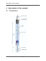
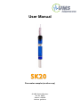
User Manual SK20 Pore water sampler (suction cup) © UMS GmbH München Art. No. SK20 Version 12/2008 Authors: ge/tk/ma SK20 Content 1 SK20 1.1 1.2 1.3 1.4 1.5 2 Safety instructions and warnings Content of delivery Foreword Intended Use Guarantee Description of the sampler 2.1 2.2 2.3 2.4 2.5 3 4.1 4.2 5 5.1 5.2 5.3 4 4 4 5 5 6 Construction The ceramic cup Acrylic glass shaft Suction tube Protection tube 6 7 7 7 7 Installation and operation 3.1 3.2 3.2.1 3.2.2 3.2.3 3.2.4 3.2.5 3.2.6 3.3 3.4 3.4.1 3.4.2 4 4 8 Rinsing Installation Auger Slurrying the cup Jacket tubes Installation angle Drilling Lay the tubes Assembly and start-up Collecting sampled solution Discontinuous method Continuous method 8 8 8 9 9 9 10 10 10 11 11 13 Service and maintenance 13 Empty suction cups before frost Cleaning and storage 13 13 Protecting the measuring site 14 Theft and vandalism Cable and tube protection Frost 14 14 14 6 Troubleshooting 15 7 Appendix 16 7.1 7.2 7.3 7.4 Technical specifications Accessories Glossary Units 16 18 21 22 2/28 SK20 8 Reference list 23 9 Index 25 Your addressee at UMS 28 3/28 SK20 1 SK20 1.1 Safety instructions and warnings Please pay attention to the following possible causes of risk: Caution! Use only implosion-proof sampling bottles. Danger of injury! The ceramic cup is fragile. Excessive load, bending or force can lead to the break. Never touch the ceramic cup. Grease, oil or sweat will disturb the quality. 1.2 Content of delivery The delivery of a SK20 includes: 1.3 SK20 pore water sampler with suction tube (standard tube length 5 m) inside reinforced protection tube Foreword Measuring systems must be reliable and durable and should require a minimum of maintenance to achieve target-oriented results and keep the servicing low. Moreover, the success of any technical system is directly depending on a correct operation. At the beginning of a measuring task or research project the target, all effective values and the surrounding conditions must be defined. This leads to the demands for the scientific and technical project management which describes all quality related processes and decides on the used methods, the technical and measurement tools, the verification of the results and the modelling. The continuously optimized correlation of all segments and it's quality assurance are finally decisive for the success of a project. So please do not hesitate to contact us for further support and information. We wish you good success with your projects. Yours, Georg von Unold 4/28 SK20 1.4 Intended Use Pore water samplers are designed to extract soil water from saturated and non saturated soils. To extract a soil water solution, a negative pressure has to be applied. The cups are made of a special ceramic with constant and defined pore distribution with small chemical activity and adsorption. 1.5 Guarantee UMS gives a guarantee of 12 months against defects in manufacture or materials used. The guarantee does not cover damage through misuse or inexpert servicing or circumstances beyond our control. The guarantee includes substitution or repair and package but excludes shipping expenses. Please contact UMS or our representative before returning equipment. Place of fulfilment is Munich, Gmunder Str. 37! 5/28 Description of the sampler 2 Description of the sampler 2.1 Construction 6/28 Description of the sampler 2.2 The ceramic cup The cup consists of 70% porous Al2O3 and about 30% SiO2 sinter material. The special manufacturing process guarantees homogeneous porosity with good water conductivity and very high firmness. Compared to conventional porous ceramic the cup is much more durable. The bubble point is higher than 2 bar. The cup has been tested by the Technical University Munich, Center of Life and Food Sciences Weihenstephan, department forest nutrition and water balance. The applied test procedure has been proposed to the DIN-NORM committee NAW12/UA5/AK4 for implementation as a DIN standard. Suitability as been approved for: Nitrate Chloride Sulphate Sodium Magnesium DOC Calcium It is not suitable for: Heavy metals and Aluminium (see chapter “Scientific background”) Before first use treat the cup as described in chapter “Rinsing”. 2.3 Acrylic glass shaft With the shaft it is possible to install the sampler in the required depth. The shaft consists of an extremely resistant Acrylic material with highest durability against bending, scratches, breakage. 2.4 Suction tube The suction tube is made of polyethylene, outer diameter is 2.8 mm and the inner diameter 1.6 mm. Normally the suction tube is connected to a sampling bottle with vacuum. 2.5 Protection tube The reinforced protection tube prevents that the suction tube is bended or damaged by rodent bite. 7/28 Installation and operation 3 Installation and operation 3.1 Rinsing Always rinse each ceramic cup or plate with 500 to 2000 ml deionised water, and then condition them with the adequate soil water solution. If there is enough time before the first samples should be analyzed you can do without rinsing and then discard the samples from the first week, or at least 1000 ml. It might be considerable to discard an amount of 500 to 2000 ml of your first won samples. When charged with high amounts of acidity sintered ceramic materials corrode and release Aluminium. Therefore, we strictly oppose to rinse the ceramics with acid solution, although this is recommended in some literature. We do not recommend to rinse the cup with hydrochloric acid as this might destruct the cup. This will breach the warranty! Before installation it is recommendable to immerse ceramic cups in de-ionised water for some time, preferably over night, so the pores will be water saturated. 3.2 3.2.1 Installation Auger The ceramic cup has to have a good capillary contact to the soil matrix. Therefore, the ceramic cup should fit into the drilling as tight as possible. To achieve this, the auger tip should exactly have the same diameter as the cup. The shaft itself should have a space of 1 to 2 mm for easy insertion, low disturbance and possibility to control the fitting of the cup. UMS offers the special gouge auger TB-20 with a tapered tip as an accessory. This auger has a diameter of 20 mm on the first 5 cm of the tip, and 22 mm on the further section. 8/28 Installation and operation 3.2.2 Slurrying the cup It is only recommendable to slurry the ceramic cup in a highly sandy or stony soil. Slurry the cup with a paste made of the soil taken from the bottom of the augered hole. Optionally you may use washed quartz sand (mesh size 1200). Mix a viscous paste with water and fill it into the hole with a properly sized pipe. In horizontal installations blow the paste into the pipe. Note that fine material might be washed out by heavy drainage water. Then, the cup might lose it's capillary contact to the soil. In this case repeat the slurrying. Also note that sandy soils drain quickly (see pF/wc curve for sandy soils). Therefore, soil solution can only be extracted with a suction cup at low soil water tension (pF < 2 or unbound water). Sandy soils drier than -10 kPa only have small volumetric content of water as large pores are already vented. 3.2.3 Jacket tubes Specially in coarse sand or pebbly soils it might be necessary to install jacket tubes as a drilled hole collapses before the suction cup is inserted. If the samplers are installed in jacket tubes ensure that condensed water or leachate is conducted away from the suction cup. In horizontal installation a decline of 3% towards the manhole is suitable. Note that the jacket tubes should not be installed closer than 50 cm away from the suction cup. If the jacket tubes are installed with percussion drilling machine the final 100 cm should not be rammed but manually drilled to prevent compaction of the soil. Beside in compact sand also drilling rockets can be used. 3.2.4 Installation angle The sampler should be installed in a way that the major flow path is not disturbed by the sampler’s shaft. If for example the flow path is vertical the shaft should be installed with an angle of at least 20° away from the vertical line. 9/28 Installation and operation 3.2.5 Drilling Put a mark on the auger to drill to the proper depth. Take away the organic layer with a shovel to avoid that the auger pushes organic material into lower layers. Drill the hole. If required insert the slurry paste into the hole with a pipe. Immediately insert the sampler. In pebbly soils you only have 10 seconds until the slurry paste might drain away. Do not use force when inserting the shaft. Do not use tools or a hammer. The SK20 sampler has a black mark on the top end of the shaft. If the shaft is not installed vertically this mark should point upwards then the opening of the suction tube inside the cup is at the lowest position of the cup. In case put pack the organic layer and tighten the soil to close the gap between the shaft and the augered hole. Push the supplied rubber surface water retaining disk over the shaft to prevent that surface water runs along the shaft. Optionally the top part of the hole can be sealed with swellable Bentonite pellets. 3.2.6 Lay the tubes Tubes should be buried in a depth of at least 10 cm. If the system should work year round the suction tubes have to be installed in a frost free depth. UMS supplied samplers have a reinforced protective tube which protects the suction tube. It is recommendable to insert tubes without a protective tube in proper plastic protection tubes. 3.3 Assembly and start-up Insert each suction tube into a sampling bottle. In a discontinuous system attach your vacuum pump to each sampling bottle, create the required vacuum and then lock the bottle. In an extended vacuum system connect all sampling bottles with vacuum tubes and with your vacuum unit. Start to evacuate the 10/28 Installation and operation system. Please refer to the manual of your vacuum unit for instructions. A vacuum should assemble. If no vacuum is established, check your system for leaks. With the first won solution the system is flushed. Discard the first samples. 3.4 3.4.1 Collecting sampled solution Discontinuous method UMS sampling bottles are either plugged with a clamp or with a fitting as seen the photo. Open the vacuum tube to vent the bottle. Screw off the cap and collect the sample, or replace the bottle with a clean one. Put back the bottle cap and evacuate the bottle with your pump. Now bend the vacuum tube to seal it and remove your pump. Reattach the fitting or the clamp. 11/28 1. Take off the plug from 2. Connect the vacuum the sampling bottle tube from the pump with the connector piece. Evacuate the bottle to the needed vacuum. 3. Bend the blue tube on the sampling bottle to retain the vacuum when you take off the connector piece. 4. Immediately put back the plug on the tube of the bottle. Now you can release the short tube. Installation and operation Procedure of the discontinuous method 12/28 Service and maintenance 3.4.2 Continuous method In a system with continuous vacuum, switch off the vacuum unit. Then vent the system. Now collect all samples from the sampling bottles and reassemble the system. In case check the Tensiometer readings and the sampled amounts and adjust the settings of your vacuum unit. 4 Service and maintenance 4.1 Empty suction cups before frost If suction cups should remain installed during periods with temperatures below freezing point, they must be emptied to prevent frost damage. Please note, that in times free of snow but with air temperatures below 0°C, the area of frost declines from the soil surface into deeper soil horizons. Required tools for emptying: One retaining tube clamp for each suction cup, a syringe (50 ml) and a vacuum pump. How to proceed: With the vacuum pump, completely extract the water left in the suction cup. Attach the syringe to the extraction tube. Press 20 ml of air into the cup to achieve a positive pressure of approx. 100 hPa. Lock the extraction tube with a tube clamp to keep up the overpressure. As soon as water inside the extraction tube is frozen, the suction cup cannot be emptied anymore. The ceramic cup might be damaged by the frozen water. 4.2 Cleaning and storage For cleaning, wipe of the shaft with a moist cloth. The suction cups should be stored in a position where a deformation of the shaft is avoided. Do not touch the ceramic with your fingers. 13/28 Protecting the measuring site 5 Protecting the measuring site 5.1 Theft and vandalism The site should be protected against theft and vandalism as well as against any farming or field work. Therefore, the site should be fenced and signposts could give information about the purpose of the site. 5.2 Cable and tube protection Cables and tubes should be protected against rodents with plastic protection tubes. UMS offers dividable protection tubes as accessory. For long term studies we recommend to dig cables and tubes a few centimetres below soil surface inside protection tubes. 5.3 Frost For all-season operation install suction tubes in a frost-free depth and the sampling bottles in an insulated and buried box. 14/28 Troubleshooting 6 Troubleshooting If no or only a little amount of water is extracted over a longer period of time please check the following: If you have an automatic regulation, for example with the VS vacuum station, and the pump repeatedly switches on the reason could be a leak in the system. Check all tubes and connections for tightness. Sampling cups have a very small sphere of influence. Depending on their hydraulic contact the sampler either extracts water from the primary pores or, specially in heterogeneous soils, the secondary pores (cracks, macro pores). Therefore, results can turn out variously in extremely heterogeneous soils. As water can only be extracted from a moist soil results can be poor during summer or in dry soils. Pathways caused by mouse holes or roots quickly conduct water into lower horizons where the water accumulates [Riess 1993]. Fine particles can clog the ceramic pores over the time. To flush the ceramic while installed will only have a short-lived success as the particles are only moved into the surrounding soil. Clogging should be diminished from the beginning by keeping the flow rate as low and as constant as possible, for example by a tension controlled vacuum. The vacuum should only be as high as required. Test have shown that these measures reduce clogging [Riess 1993]. 15/28 Appendix 7 Appendix 7.1 Technical specifications Technical Specifications SK20 Shaft Acrylic, 20 mm Extraction tube Polyethylene, inside 1.6 mm Protective tube PVC, with reinforced fabric, 11 x 5 mm Cup type K100 Cup size Length 54 mm 0,8, diameter 20 mm - 0.5 Active surface 34 cm2 1 Filling volume 8 ml 1 Cup porosity 45% 2 % Pore size 1 m 0.1 m Hardness (Mohs) 7 MH Flexural strength 60 N/mm2 0,5 Compressive strength 240 N/mm2 10 Coefficient of elongation 5.8 x 10⁻⁶ 3 Chemical Compound Al2O3 70 0,5 % by volume SiO2 29 0,5 % by volume R2O 0,8 0,1 % by volume 16/28 Appendix 17/28 Appendix 7.2 Accessories Description Portable vacuum case without regulation, internal pump for max. vacuum -85 kPa (-0.85 bar) or pressure max. 3.5 bar, rechargeable battery 7 Ah, particle filter, gauges for vacuum and pressure, in watertight storm case 30x25x13 cm, 4.8 kg; supplied incl. recharger 230 VAC Please order additionally: Mains recharger 110 VAC ... 230 VAC, for VacuPorter, incl. set of international plug adapters Hand-operated vacuum floor pump, volume 410 ml per stroke, achievable vacuum 0 … -80 kPa, aluminum body, steel foot, height 57 cm, weight 2 kg, for evacuation of larger volumes VacuPorter VPS-2 Sampling bottle Sampling bottle 500 ml, implosion protected, with screw cap for up to 3 tubes Sampling bottle 1000 ml, implosion protected, with screw cap for up to 3 tubes Sampling bottle 2000 ml, implosion protected, with screw cap for up to 3 tubes Spare cap for sampling bottle GL45, blue Clip for wall mounting of sampling bottles Art. no. VacuPorter vp.110VAC VPS-2 SF-box SF-500 SF-1000 SF-2000 SFK SF-CLIP PVC-box for 6 sampling bottles, L 400 x B 300 x H 350 mm, SF-BOX incl. 6 lead-throughs PG9 Insulated box, dimension outside 600 x 400 x 365 mm, inside SF-ISOBOX 510 x 310 x 300 mm, incl. 14 lead-throughs PG9 for protective tubes SF-Protect Automatic overflow valve for sampling bottles 18/28 Appendix SF-protect VS-pro VS-single Vacuum systems VS-pro 2-channel vacuum unit for two adjustable vacuum circuits 0...-85 kPa, one controllable with optional Tensiometer T4 or T8, display keypad, Aluminum enclosure 26x16x22cm, IP66, incl. tensioLink connector tL-8/USB-Mini and software tensioVIEW VS-twin 2-channel vacuum system, without display/keypad, adjustable vacuum pump 0… -85 kPa, for two constant vacuum circuits, one controllable with optional Tensiometer T4 or T8, Aluminium enclosure 26x16x22cm, IP66, incl. tensioLINK connector tL-8/USB-Mini and software tensioVIEW 1-channel vacuum system, incl. adjustable vacuum pump 0… VS-single -85 kPa, for one constant vacuum circuit, controllable with optional Tensiometer T4 or T8, Aluminium enclosure 26x16x22cm, IP66, tensioLINK interface RS485 for external data logger connection 19/28 Appendix b.TB-20 TBE-100 Special gouge auger, shaped tip for UMS-Tensiometers and b.TB-20 UMS-suction cups, diameter 20 mm, length 1250 mm, with hammering head (without elongation) Gouge auger elongation 100 cm for Tensiometer and suction b.TBE-100 cup augers Cable protection tube, inner diam. 8,7 mm, max. cable diam. 4 mm, dividable Cable protection tube, inner diam. 12,5 mm, max. cable diam. 7 mm, dividable Cable protection tube, inner diam. 24,2 mm, max. cable diam. 14 mm, dividable Cable protection tube, inner diam. 30,0 mm, max. cable diam. 18 mm, dividable 20/28 ks.DN-10 ks.DN-14 ks.DN-23 ks.DN-37 Appendix 7.3 Glossary Suction cup, pore water sampler or lysimeter Different terms are common. In this context it is an instrument consisting of a hydrophilic membrane, shaft and suction tube which is used to extract soil water solution from unsaturated zones. We do not use the term lysimeter for pore water samplers as we define a lysimeter as a monolithic soil column. Lysimeter Container with defined surface, filled with soil and with at least one outlet. Used for quantification of water and substance flows, decay/reaction processes and simulation. Tensiometer Instrument for measuring soil water tension. Vacuum Pressure below atmospheric pressure. 21/28 Appendix 7.4 Units pF hPa kPa=J/kg MPa bar psi %rH 1 -10 -1 -0,001 -0,01 -0,1450 99,9993 2,01 -100 -10 -0,01 -0,1 -1,4504 99,9926 2.53 -330 -33 -0,033 -0,33 -4,9145 99,9756 Tensiometer 2.93 ranges* -851 -85,1 -0,085 -0,85 -12,345 3 -1.000 -100 -0,1 -1 -14,504 99,9261 4 -10.000 -1.000 -1 -10 -145,04 99,2638 -15.136 -1.513 -1.5 -15 -219,52 98,8977 5 -100.000 -10.000 -10 -1 00 -1.450,4 92,8772 Air-dry** 6 -1.000.000 -100.000 -100 -1 000 -14.504 47,7632 Oven-dry 7 -10.000.000 -1.000.000 -1.000 -10 000 -145.038 0,0618 Wet Field capacity Permanent 4.18 wilting point * standard measuring range of Tensiometers ** depends on air humidity Note: 1 kPa corresponds to 9,81 cm water column 22/28 Reference list 8 Reference list Czeratzki, W.; 1971: Saugvorrichtung für kapillar gebundenes Bodenwasser. Landforschung Völkerode 21, 13-14 DVWK; 1990: Gewinnung von Bodenwasserproben mit Hilfe der Saugkerzenmethode. DVWK Merkblätter, Heft 217 DVWK; 1980: Empfehlungen zum Bau und Betrieb von Lysimetern Grossmann, J.; Quentin, K.-E.; Udluft, P.; 1987: Sickerwassergewinnung mittels Saugkerzen – eine Literaturstudie. Z. Pflanzenernährung u. Bodenkunde 150, 281-261 G.HENZE, 1999: Umweltdiagnostik mit Mikrosystemen, Verlag Wiley-VCH, ISBN 3-527-29846-0. RAMSPACHER, P., 1993: Erste Erfahrungen mit tensiometergesteuerten Unterdrucklysimetern zur Erstellung von Sickerwasserbilanzen (Lysimeterstation Wagna), Bericht über die 3. Gumpensteiner Lysimetertagung „Lysimeter und ihre Hilfe zur umweltschonenden Bewirtschaftung landwirtschaftlicher Nutzflächen“, BAL Gumpenstein, 20.-21.4.1993, S. 67-72. HARTGE, HORN, 1992: Die physikalische Untersuchung von Böden, Verlag Enke, ISBN 3 432 82123 9. FEICHTINGER, F., 1992: Erste Erfahrungen beim Einsatz eines modifizierten Feldlysimeters, Bericht über die 2. Gumpensteiner Lysimetertagung „Praktische Ergebnisse aus der Arbeit mit Lysimetern“, BAL Gumpenstein, 28.-29.4.1992, S. 59-62. KLAGHOFER, E., 1994: Antworten auf die 7 Fragen an uns Lysimeterbetreiber, Bericht über die 4. Gumpensteiner Lysimetertagung „Übertragung von Lysimeterergebnissen auf landwirtschaftlich genutzten Flächen und Regionen“, BAL Gumpenstein, 19.-20.4.1994, S. 5-7. ROTH, D., R. GÜNTHER und S. KNOBLAUCH, 1994: Technische Anforderungen an Lysimeteranlagen als Voraussetzung für die Übertragbarkeit von Lysimeterergebnissen auf landwirtschaftliche Nutzflächen, Bericht über die 4. Gumpensteiner Lysimetertagung „Übertragung von Lysimeterergebnissen auf landwirtschaftlich 23/28 Reference list genutzten Flächen 20.4.1994, S. 9-21. und Regionen“, BAL Gumpenstein, 19.- SCHWABACH, H. und H. ROSENKRANZ, 1996: Lysimeteranlage Hirschstetten - Instrumentierung und Datenerfassung, Bericht über die 6. Gumpensteiner Lysimetertagung „Lysimeter im Dienste des Grundwasserschutzes“, BAL Gumpenstein, 16.-17.4.1996, S. 41-45. KRENN, A., 1997: Die universelle Lysimeteranlage Seibersdorf Konzeption, Bericht über die 7. Gumpensteiner Lysimetertagung „Lysimeter und nachhaltige Landnutzung“, BAL Gumpenstein, 7.9.4.1997, S. 33-36. EDER, G., 1999: Stickstoffausträge unter Acker- und Grünland, gemessen mit Schwerkraftlysimetern und Sickerwassersammlern, Bericht über die 8. Gumpensteiner Lysimetertagung „Stoffflüsse und ihre regionale Bedeutung für die Landwirtschaft“, BAL Gumpenstein, 13.-14.4.1999, S. 93-99. KUNTZE, ROESCHMANN, SCHWERDTFEGER, Bodenkunde, Verlag UTB Ulmer, ISBN 3-8001-2563-3. 1988: Starr, J.L.; Meisinger, J.J. ; Parkin, T.B.; 1991: Experience and knowledge gained from vadose zone sampling. In: NASH, R.G.; Leslie A.R. (Eds.): Groundwater Residue Sampling Design. Am. Chem. Soc. Symp. Series 465, 279-289 Udluft, P.; Quentin, K.-E.; Grossmann, J.; 1988: Gewinnung von Sickerwasser mittels Saugkerzen – Verbesserung der Probenahmetechnik und Minimierung der Veränderung der chemischen und physikalischen Eigenschaften des Sickerwassers. Abschlußbericht zum Forschungsvorhaben DU 3/10-1. Institut für Wasserchemie der TU München. 24/28 Index 9 Index A M auger...............................................10 maintenance .....................................4 B N black mark.......................................10 buried box .......................................14 NAW12/UA5/AK4..............................7 O C organic layer ...................................10 capillary contact ................................8 P D de-ionised water................................8 DIN-NORM........................................7 porous Al2O3 .....................................7 protection tube ..................................7 protection tubes ..............................14 F R frost-free..........................................14 Rinsing..............................................8 G S Guarantee .........................................5 shaft ..................................................7 suction tube ......................................7 Suitability ..........................................7 J T jacket tubes.......................................9 Technical specifications..................16 25/28 Index water conductivity .............................7 W 26/28 Index 27/28 Your addressee at UMS Your addressee at UMS Sales: Georg v. Unold Tel:+49-89-126652-15 Email: [email protected] About this manual: Thomas Keller Tel:+49-89-126652-19 Email: [email protected] UMS GmbH D-81379 München Gmunderstr. 37 email: [email protected] Ph.: +49-89-126652-0 Fax: +49-89-126652-20 Strictly observe rules for disposal of equipment containing electronics. Within the EU: disposal through municipal waste prohibited - return electronic parts back to UMS. Rücknahme nach Elektro G WEEE-Reg.-Nr. DE 69093488 28/28