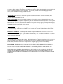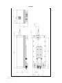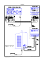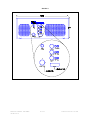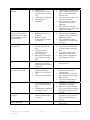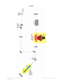
1
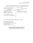
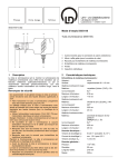
USER’S MANUAL DPSS LASER SERIES 3500-SMPS Covers Models 35xx-yyy DPSS User’s Manual: 3500-SMPS 780-023 Rev. F 1 of 23 Created on 03/27/12 11:07 AM TABLE OF CONTENTS PAGE Laser Safety 3 Warranty Information 4 Product Description / Dimensions 5 Utility Requirements and System Installation 7 System Controls 8 Daily Operation of the Laser System 10 Troubleshooting 14 Appendix I - Common Laser Beam Terms 16 Appendix II - DPSS Laser Theory 17 Appendix III - Controlling the Laser Externally 19 Appendix IV - Storing Your Laser 21 Contacting DPSS Lasers Inc. 22 Final Test Documentation DPSS User’s Manual: 3500-SMPS 780-023 Rev. F Attached 2 of 23 Created on 03/27/12 11:07 AM LASER SAFETY Before operating this equipment, users should refer to ANSI Standard Z136.1 that outlines precautions for safe operation of laser equipment and specifically recommends that: 1. 2. Users should have initial eye examinations prior to operating laser equipment followed by periodic reexaminations. Users should use appropriate eye protection when operating laser equipment. The standard is available from the Laser Institute of America (LIA), telephone number (407) 380-1553. This equipment is powered by a high voltage power supply capable of high current output. There are no user serviceable components in this system. These lasers comply with DREW radiation performance standards, 21CFR subchapter J. BEWARE OF HAZARDOUS LASER RADIATION. AVOID DIRECT EXPOSURE TO THE BEAM. DO NOT STARE AT SCATTERED OR REFLECTED LIGHT. STRICT OBSERVANCE OF THE FOLLOWING WARNING LABELS IS ADVISED. This label is affixed to the laser head cover next to the laser emission indicator. This laser has a maximum output of 4W at 355nm. This label is displayed on the side of the laser head. This label is attached next to the Laser output port shutter. This Serial Number/Model number label is located on the back of the laser head, power supply, and cooling system. DPSS User’s Manual: 3500-SMPS 780-023 Rev. F 3 of 23 This label is affixed to the back of the power supply. Created on 03/27/12 11:07 AM LIMITED WARRANTY All mechanical, electrical and optical parts and assemblies when operated under normal conditions and in accordance with the product instructions are warranted to be free from defects in workmanship and materials for the first full year following delivery of the equipment. The following warranty conditions shall apply to all laser systems, unless amended in writing by DPSS Lasers Inc. ADJUSTMENT – No electrical, mechanical or optical adjustments to the laser system are permitted, unless expressly authorized by DPSS Lasers Inc. PARTS AND LABOR - New or factory-built replacements for defective parts will be supplied for one (1) year from date of delivery of the equipment. Replacement parts are warranted for the remaining portion of the original warranty period. There will be no charge for repair of products under warranty where the repair work is done by DPSS Lasers Inc. However, DPSS Lasers Inc. shall not be responsible for any shipping or transportation charges, which shall be the sole responsibility of the customer. NOT COVERED – Damage due to abuse, improper installation or application, alteration, accident, negligence in use, improper storage, transportation or handling is not covered by this warranty. This warranty shall not apply where the original equipment identifications have been removed, defaced or altered. DAMAGE IN SHIPMENT - Your laser product should be inspected and tested as soon as it is received. The product is packaged for safe delivery. If the product is damaged in any way, you should immediately file a claim with the carrier or, if insured separately, with the insurance company. DPSS Lasers Inc. will not be responsible for damage sustained in shipment. CLAIMS ASSISTANCE - Call DPSS Lasers Inc. Customer Service or your local distributor for assistance. Give our representative the full details of the problem. Helpful information or shipping instructions will be provided. If requested, estimates of the charges for non-warranty or other service work will be supplied before work begins. Products being returned for repair must be shipped in their original shipping cartons to avoid damage. DISCLAIMER - THIS WARRANTY SHALL BE IN LIEU OF ALL OTHER WARRANTIES EXPRESS OR IMPLIED AND SHALL BE IN LIEU OF ALL WARRANTIES OF FITNESS AND MERCHANTABILITY. DPSS Lasers Inc. SHALL NOT BE LIABLE FOR INCIDENTAL OR CONSEQUENTIAL DAMAGES OF ANY NATURE OR KIND WITH RESPECT TO ANY PRODUCTS OR SERVICES SOLD OR RENDERED HEREUNDER AND UNDER NO CIRCUMSTANCES WILL DPSS Lasers Inc.'s LIABILITY EXCEED THE COST OF REPAIR OR REPLACEMENT OF THE DEFECTIVE ITEM OF EQUIPMENT. DPSS Lasers Inc. NEITHER ASSUMES NOR HAS AUTHORIZED ANY OTHER PERSON TO ASSUME FOR IT ANY OTHER LIABILITY. DPSS User’s Manual: 3500-SMPS 780-023 Rev. F 4 of 23 Created on 03/27/12 11:07 AM PRODUCT DESCRIPTION The DPSS Lasers Inc. Series 3500 DPSS Laser The Series 3500 DPSS laser (patent # 6,002,695) is a high repetition rate, Q-switched, Diode pumped Nd: Vanadate system, employing intra-cavity doubling and tripling for efficient ultra-violet generation. With specified average powers of one tenth watt (0.1W) to five watts (5.0W) at 355nm and at repetition rates from 30 kHz to 100 kHz, the DPSS laser is specifically designed to meet the needs of the OEM system designer. Combining the power conversion efficiency of diode pumped solid state technology with proprietary laser cavity design and a sealed housing, the Series 3500 is ideally suited to industrial environments. The laser requires only regular household electrical power, no external water-cooling and operates at or near room temperature. Thermoelectric coolers transfer heat to the cast aluminum base while a closed cycle cooling system transfers the heat to the room air. A proprietary mechanical design, utilizing stress-relieved components, eliminates cavity alignment for the life of the laser. The laser output is vertically polarized and the mode is TEMoo. The Series 3500 DPSS laser has been designed for materials working applications including metals, organics, and inorganics. Specific applications include micromachining/ablating of various metallic and non-metallic materials, polymerization of photopolymers, such as those used in Rapid Prototyping and bio-fluorescence. STANDARD SPECIFICATIONS, SERIES 3500 DPSS LASER: Nd:YVO4, Frequency Tripled, Q-switched Laser OPTICAL (variations based on model number): Wavelength Average power Pulse length Repetition rate (factory set) Mode Beam diameter (1/e²) Beam divergence (full angle) Polarization, linear, vertical Beam pointing stability at constant temp Power stability over eight hours First pulse suppression 354.7 0.1 – 5.0 20 - 60 30 - 100 M2<1.25 1.5 <0.5 100:1 <50 <5 Yes nm W nsec kHz TEMoo mm mrad ELECTRICAL: Input voltage Power consumption, maximum Ambient operating temperature (non-condensing) 90-240 500 10-35 VAC W C PHYSICAL: Laser head dimensions in inches (LWH) Laser head weight Laser power supply dimensions in inches (LWH) Laser power supply weight Cooling system dimensions in inches (LWH) Cooling system weight 20.0 x 7.5 x 6.5 30 lbs. 12.2 x 13.5 x 5.4 11 lbs. 11.3 x 8.8 x 15.3 20 lbs. DPSS User’s Manual: 3500-SMPS 780-023 Rev. F 5 of 23 rad % Created on 03/27/12 11:07 AM FIGURE 1 DPSS User’s Manual: 3500-SMPS 780-023 Rev. F 6 of 23 Created on 03/27/12 11:07 AM UTILITY REQUIREMENTS AND SYSTEM INSTALLATION INCOMING INSPECTION: Immediately upon receipt, the laser should be unpacked and inspected for shipping damage. If none is evident, test for satisfactory operation. REQUIRED TOOLS FOR INSTALLATION: - Large flat screw driver or wrecking bar Use: Opening the shipping crate. - Water, 2 quart (distilled) Use: Laser coolant. - Isopropyl alcohol, 1/2 cup Use: Laser coolant additive. - Safety glasses for all persons present. (OD>5+ @ 355nm) Use: Laser eye safety. - Calibrated laser power meter – Coherent Lasermate / LD10 or equivalent Use: Verifying laser performance. - One fluorescent card or business card. Matte surface. Use: Beam diagnostics and alignment. - 3/16” Allen driver (optional) Use: Attaching the laser to the work surface if needed. UNPACKING: Open the box and check the packing list. Verify that all materials are present. Note: Retain all packing materials. After unpacking, inspect the box and all components of the laser for damage. If any damage is found, contact the carrier for immediate on-site inspection. All claims for damage should be directed to the carrier. Call DPSS Lasers Inc. Customer Service for further instructions. CAUTION: THE USE OF CONTROLS, ADJUSTMENTS, OR PERFORMANCE OF PROCEDURES OTHER THAN THOSE SPECIFICED HEREIN MAY RESULT IN HAZARDOUS RADIATION EXPOSURE. Note: DO NOT remove any covers or panels unless specified! VENTILATION: Provide adequate ventilation so that the ambient temperature of the air is in the range of 20-30C. This is the preferred operating temperature range for the laser. The lasers will operate satisfactorily over a greater range, 1035C, but derated power may be experienced. It is important that air inlets on the back and sides of the laser power supply and cooling unit are not obstructed and that the exited hot air is not allowed to recirculate into the air inlets. MOUNTING: The laser head is designed to be mounted in any attitude. For testing purposes, the laser can simply stand on a table on its feet. For permanent installation, the laser should be mounted to the user's system or optical bench. The dimensions of the mounting feet are shown in the outline drawings in the Product Description chapter (see Figure 1). The mounting feet are designed to provide mechanical isolation between the laser resonator structure and the mounting surface. This feature prevents any lack of flatness of the mounting surface, bending of the surface, or differential thermal expansion from affecting the laser mirror alignment. When all three feet are rigidly attached to the mounting surface, the laser will not move. Do not attempt to mount the laser by the base itself or some manner other than with the feet or other DPSS Lasers Inc. approved mounting device. If screw access from the bottom is not available, intermediate mounting plates can be used. POWER REQUIREMENTS: The laser power supply and cooling system are universal input devices. They will operate at any standard AC line voltage, worldwide (90 – 240 VAC). All models operate at 50Hz or 60Hz input. DPSS User’s Manual: 3500-SMPS 780-023 Rev. F 7 of 23 Created on 03/27/12 11:07 AM SYSTEM CONTROLS Before attempting to operate the laser, familiarize yourself with its various controls. LASER OUTPUT SHUTTER: The mechanical laser output shutter is located on the front bezel of the laser head. Open the output shutter on the laser head by rotating the wheel until the detent appears on top and the wheel clicks into place. POWER SUPPLY CONTROL BUTTONS (REFER TO FIGURE 3): The following is a description of the control buttons found on the power supply: 1. Key Switch: Enables all the control devices within the power supply to turn on. a) ‘O’ OFF position b) ‘1’ ON position 2. Large Green ‘POWER ON’ Light: Indicates whether line voltage is present. a) Not illuminated: No AC line voltage present b) Illuminated: AC line voltage present 3. ‘STANDBY’ Button: Places the laser in a ‘STANDBY’ mode or resets the system when a fault occurs. It is preferable to press this button and return the laser to the ‘STANDBY’ mode before turning off the key switch on a system that is emitting laser output. a) ‘STANDBY’ Amber Light: Laser is in the ‘STANDBY’ mode. The laser diode is off and the Q-Switch is in the ‘DISABLE’ mode. b) ‘FAULT’ Red Light: The laser has experienced a fault. These include: i) Safety interlock open. ii) Cables J2 and J3 interchanged at power supply or head. iii) No water flow. iv) Baseplate temperature over limit. v) Diode current over limit. vi) Diode temperature over limit. vii) Power supply temperature over limit. 4. ‘LASER ON’ Button: When pressed, the ‘WARM UP’ light will illuminate indicating that the warm up countdown sequence has begun. After 60 seconds, the ‘WARM UP’ light will turn off and the ‘READY’ light will illuminate indicating that the laser is ready to produce laser output once the ‘Q-SWITCH’ is enabled. If the ‘STANDBY’ button is pressed while either the ‘READY’ or ‘WARM UP’ lights are illuminated, the system will immediately revert to the ‘STANDBY’ mode and the ‘WARM UP’ countdown sequence will be reset. a) ‘READY’ White Light: Laser is ready to produce laser output. b) ‘WARM UP’ Amber Light: Laser is in the 60 second count down sequence. 5. ‘Q-SWITCH’ Button: This button toggles the Q-switch between ‘ENABLE’ and ‘DISABLE’ mode. It will operate only when ‘READY’ White Light is illuminated. a) ‘ENABLE’ White Light: The Q-switch is enabled, laser emitting pulsed radiation. b) ‘DISABLE’ Amber Light: The Q-switch is disabled, laser emitting CW radiation. CONNECTING THE COOLING SYSTEM (REFER TO FIGURE 2): 1. The laser system is supplied with two water hoses. A flow sensor is attached to one hose at the female end (SUPPLY). Connect this end of the hose to the male port on the laser head. Connect the other end of this hose (SUPPLY) to the port on the cooling system marked with an arrow pointing down. 2. Connect the second hose (RETURN) to the remaining female port at the laser head. Connect the other end to the remaining port on the cooling system marked with an arrow pointing up. 3. Remove plastic filler cap for the water reservoir on the cooling system. 4. Fill the reservoir with 1/2 cup Isopropyl Alcohol and top off with distilled water. Note: Isopropyl/distilled water solution is permitted for use in all “distilled only” locations. DPSS User’s Manual: 3500-SMPS 780-023 Rev. F 8 of 23 Created on 03/27/12 11:07 AM Note: The water level will drop when the unit is first turned on as air in the hoses and cold plate is replaced with water. The reservoir will need to be topped off with distilled water. If the cooling unit displays a low fluid alarm during this time, simply cycle the power OFF and ON again to reset. CONNECTING THE LASER CABLES (REFER TO FIGURE 2): 1. Place the laser head on a table. Close the shutter. 2. Located the electrical umbilical that connects the laser head to the power supply. Secure each connector to its corresponding mate at the laser head indicated by the following labels: Diode, Scanner, RF, J2, J3, and finally connect the two-pin red interlock cable to its mating connector on the flow sensor in the water hose. 3. Repeat the above step with the free end of the umbilical bundle at the power supply end. The red, 4-pin connector will connect to the “Interlock” location at the power supply. 4. With the cooling system switch in the OFF position, connect one end of an AC power cable into the cooling system and then into a suitable AC power outlet. 5. With the key switch in the OFF position (“0”), connect the AC power cable into the rear of the power supply and then into a suitable AC power outlet. TURNING ON THE LASER SYSTEM FOR THE FIRST TIME (Refer to Figure 3): 1. Turn on the Cooling system. Verify that the water in the reservoir is bubbling vigorously and fill the reservoir as necessary. Allow the system to run for two minutes to ensure that all air has been purged from the hoses. Verify that the “manifold temp” on the cooling system display is moving toward the 23.5C set temperature. 2. Check the system for any water leaks. Note: The Cooling system temperature is factory set to 23.5C. No further adjustment of the set temperature is recommended or required. Note: A beam block (beam dump or power meter) should be placed in the beam path at all times. 3. 4. 5. 6. 7. If provided, turn on the master power switch at the rear of the power supply. The large green power indicator light at the front on the power supply should be illuminated. Turn the key switch to the ON position. Make sure the power switch on the cooling system is in the ON position and note that the cooling system turns on and the water in the reservoir begins circulating. Press the STANDBY button at the front of the power supply to clear any initial faults. If the FAULT light remains on, please turn to the troubleshooting section of this manual for instructions. The laser system is now ready for operation. To turn on the laser, press the LASERON button. The STANDBY light will extinguish, the WARMUP light will illuminate and the laser diode will be energized. After 60 seconds, the WARMUP light will extinguish and the READY light will illuminate. This indicates that the system is ready to output pulsed laser radiation. Note: Under normal conditions, some (approximately 5mW) light will be emitted from the output aperture when the laser is on and the q-switch is disabled. 8. To initiate pulsed laser radiation, press the QSWITCH button. The indicator will change from DISABLE to ENABLE and pulsed laser radiation will be emitted from the output aperture at the specified repetition rate. Note: After running the system for 20 minutes with laser output, touch the underside of the laser head with your hand and note the temperature. It should be close to room temperature and the “manifold temperature” on the cooling system display should read very near 23.5C. If the laser base appears to be getting warmer or is significantly hotter than room temperature, it is possible that the cooling system is not circulating. Contact DPSS Lasers Inc. Customer Service. DPSS User’s Manual: 3500-SMPS 780-023 Rev. F 9 of 23 Created on 03/27/12 11:07 AM DAILY OPERATION OF THE LASER SYSTEM WARNING: Install a power meter or beam block in front of the output of the laser before turning on the laser. Place the power meter or beam block approximately one foot from the laser output aperture to avoid contaminating the output window with ablated material. WARNING: If the laser beam strikes any semi-glossy or reflective surfaces, dangerous and potentially blinding reflections or scatter can result. Never work around the laser or enter a room where the laser is operating without wearing laser safety glasses! 1. The laser beam can be tracked by briefly placing a matte finish white card in the beam path. Move the card continuously to prevent burning the card. Do not place the card in the beam any closer than one foot from the output aperture of the laser. 2. When performing a cold start, the first ten minutes of operation may exhibit slight power fluctuations while the laser reaches 90% output. Over the next hour, laser power should rise from 90% to 100% of specified power. After this period, the laser output should be stable and ready to use. 3. The DPSS Lasers Inc. Series 3500 laser system is designed to operate continuously for the lifetime of the laser with very little maintenance. DPSS User’s Manual: 3500-SMPS 780-023 Rev. F 10 of 23 Created on 03/27/12 11:07 AM FIGURE 2 DPSS User’s Manual: 3500-SMPS 780-023 Rev. F 11 of 23 Created on 03/27/12 11:07 AM FIGURE 3 DPSS User’s Manual: 3500-SMPS 780-023 Rev. F 12 of 23 Created on 03/27/12 11:07 AM SHUTDOWN PROCEDURE: 1. Press the ‘Q-SWITCH’ Button. The ‘DISABLE’ light will illuminate and the ‘ENABLE’ light will extinguish. 2. Press the ‘STANDBY’ Button. The amber ‘STANDBY’ light will illuminate and the ‘READY’ light will extinguish. 3. Turn the key switch counter clockwise to the OFF position to turn the power supply off. 4. Turn off the Cooling system. Note: To extinguish the pulsed output beam for short periods of time, the system can be set to the DISABLE mode by pressing the QSWITCH button. The system can later be returned to the pulsed output state by again pressing the QSWITCH button and entering the ENABLE mode. Note: To extinguish the pulsed output beam for long periods of time (several days), the laser can either be switched off, or set to the STANDBY mode by pressing the STANDBY button. To restart the laser, follow the turn-on procedure above. Note: At any time, complete laser extinction can be achieved either by pressing the STANDBY button, switching the key switch to the OFF position, or unplugging the AC line cord. Additionally, any fault detected by the system, will immediately extinguish all laser radiation. REMOTE OPERATION (See Appendix III for more details): The DPSS laser is equipped with a connector that can be used to operate the laser remotely. A connector labeled ‘REMOTE’ is located on the back of the power supply. The individual pin functions of the ‘REMOTE’ connector are as follows: PIN # 1 2 3 4 5 6 7 8 9 IN/OUTPUT Input Input Input Power Power Power Input Power Output FUNCTION Toggles ‘Q-SWITCH’ button Toggles ‘LASER ON’ button Toggles ‘STANDBY’ button Power Ground Reference Power RUN Power Electronic Pulse Sync. USE Momentary Low Momentary Low Momentary Low +5V Supply (150mA) GND Reference -12V Supply (150mA) Active Level High +12V Supply (150mA) External Pulse Sync. New laser systems are shipped with a “JUMPER” connector that should be connected at the ‘REMOTE’ connector on the power supply when the remote function is not in use. The jumper enables PIN-7 of the ‘REMOTE’ connector and allows pulsed laser output under normal operating conditions. If the jumper is removed, pulsed laser output is suspended, regardless of the state of any other control functions. As such, PIN-7 of the REMOTE connector can be used to gate the pulse train duration. Note: The laser must be in the “LASER ON” mode and Q-switch “ENABLE” mode in order to modulate the pulse train duration, using PIN-7. (see appendix III for more information on remote operation.) DPSS User’s Manual: 3500-SMPS 780-023 Rev. F 13 of 23 Created on 03/27/12 11:07 AM TROUBLESHOOTING Note: The information in this section is intended to be used as an aid to the user in assessing problems with the operation of the laser and as a guide to assist experienced users in resolving routine problems. If there is any question about the procedures contained in this section or associated hazards, call DPSS Lasers Inc. Customer Service. Caution: These procedures could result in exposure to hazardous laser radiation or bright light sources. Procedures should be performed only by persons who are familiar with the hazards involved and with the use of appropriate safety equipment. WARNING: Do not remove any covers from the laser unless specified: 1) Unauthorized removal of covers from the laser will void all warranties. 2) There are no user serviceable components within the laser head or power supply. 3) Inexperienced handling of the components in the laser can cause severe damage. TROUBLE SHOOTING GUIDE: PROBLEM Power-On light not on Key switch on but no status LED’s on. POSSIBLE CAUSES Line cord not connected Main power switch at rear of power supply not on Cables not connected between power supply and laser head Cables J2 & J3 interchanged at head or power supply Fault light on at first turn on Interlock open Cooling system not turned on System recently turned on and water (water cooled units only) has not started flowing yet. Flow switch interlock connector (water cooled units only) not plugged in at power supply or laser head Water hoses interchanged at Cooling system (water cooled units only) Cooling system pump malfunction (water cooled units only) Laser head over temperature Power supply over temperature DPSS User’s Manual: 3500-SMPS 780-023 Rev. F 14 of 23 SOLUTION Connect line cord to power supply and suitable AC power source Turn on main power switch at read of power supply. Connect all cables between power supply and laser head Verify that all cables are well seated and there are no bent pins in the connectors Verify that J2 & J3 are correctly connected. Check all user installed interlocks for proper operation. Turn on Cooling system. Wait 30 seconds and press STANDBY button to clear fault Open Cooling system reservoir (water cooled units only) and verify that water is bubbling vigorously. Verify that the flow switch interlock cable (red twisted pair) is connected at power supply and laser head. Reverse water hose connections at Cooling system (water cooled units only) Touch laser baseplate to verify that it is close to room temperature. Touch power supply enclosure and verify that it is close to room temperature Ensure that ambient cooling air is not recirculating through power Created on 03/27/12 11:07 AM Fault light on after laser is operating. Interlock open Cooling system water not flowing (water cooled units only) Laser head over temperature Power supply over temperature No pulsed laser output after 5 minutes (assumes no faults detected and system running with laser READY and qswitch ENABLE) Low output power after one hour warm-up Power oscillation after turnon Power oscillation after several hours of operation Shutter not open REMOTE connector not connected RF BNC cable not connected at power supply or laser head Beam path partially blocked Ambient temperature too high Cooling system not functioning properly Laser misaligned Damaged or contaminated optics internal to the laser head It is normal for the laser output power to oscillate slightly during the first hour of operation Ambient temperature changing dramatically Cables J2 or J3 not seated well Cooling system malfunction Allow laser to warm-up for one hour prior to use. Verify that ambient temperature remains within acceptable operating limits. Verify that cables J2 and J3 are well connected at power supply and laser head. Verify that Cooling system is maintaining set temperature. Check optics in optical path for contamination or damage Turn of laser system and clean laser output window according to cleaning instruction in Service Appendix If necessary, an aperture can be placed one foot away from the laser head to block this green emission Contact DPSS Service Representative Poor beam quality Contaminated or damaged optics external to the laser head Contamination or damage to laser output window Scattered green emission with UV output It is normal for some green light to be emitted with the UV output Strong UV emission when qswitch is DISABLE Electronic malfunction DPSS User’s Manual: 3500-SMPS 780-023 Rev. F 15 of 23 supply or Cooling System. Check all user installed interlocks Open Cooling system reservoir and verify vigorous bubbling action of water Verify that laser baseplate is at or near room temperature Verify that the power supply chassis is at or near room temperature Ensure that there is adequate ventilation for the Cooling system and the power supply Open shutter on laser head Verify that either JUMPER or alternate control is connected to REMOTE connector Verify that RF BNC cable is connected at power supply and laser head Verify that shutter is fully open Verify that ambient temperature is within acceptable operating limits Verify that Cooling system is maintaining set temperature Refer to Service Appendix for laser alignment procedure. Created on 03/27/12 11:07 AM If the problem experienced cannot be resolved by this troubleshooting guide, please contact a DPSS Lasers Inc., Customer Service Representative at either your local distributor or directly through the DPSS Lasers Inc., Customer Service Department. For contact information, please refer to the Contacts page of this manual. DPSS User’s Manual: 3500-SMPS 780-023 Rev. F 16 of 23 Created on 03/27/12 11:07 AM APPENDIX I COMMON LASER TERMS The following is a list of the parameters that characterize the laser beam emitted from a DPSS laser: 1) Wavelength - Electromagnetic energy is transmitted in the form of a sinusoidal wave. The wavelength is the physical distance covered by one cycle of this wave; it is inversely proportional to frequency. In the case of the DPSS laser, the wavelength is expressed in nanometers. 2) Repetition Rate – Defined as the number of optical pulses emitted from the laser per second. 3) Pulse Length – The interval duration of each pulse from the laser. The pulse length is the measured length in time at half of the maximum amplitude of the pulse (FWHM). 4) Average Power – The product of the energy per pulse (joule) and the repetition rate (pulse frequency in hertz); expressed in watts. 5) Spatial Profile - In the case of the DPSS laser, the output beam is close to Gaussian or TEMoo in shape. The beam is circular in cross-section and the amplitude is E(r)= E(0) exp-(r/w)2, where r is the distance from the beam center and w is the radius at which the amplitude is 1/e of its value on the axis; w is called the beam width. Sometimes the ‘Spatial Profile’ of the laser is referred to as the ‘Mode’ of the laser. 6) Beam Diameter - As the beam in the DPSS laser is approximately TEMoo, the beam diameter is defined as the calculated distance between two exactly opposed points on the beam where the energy has dropped to 1/e^2 of its peak center energy. It can also be viewed as the diameter of a circular aperture through which 86% of the total energy of the beam will pass. 7) Divergence – The change in beam diameter with distance of an initially collimated beam. It is expressed as an angle in milliradians (mrad). 8) Polarization – The direction of the electric field vector in the laser beam. The polarization vector is always in the plane at right angles to the direction of the beam. In the case of the DPSS laser, the polarization is vertical. The value given to polarization is expressed as a ratio of the amount of vertically polarized to horizontally polarized light present in the beam. 9) Beam Pointing Stability - The full angle through which the far field beam moves, measured in microradians. DPSS User’s Manual: 3500-SMPS 780-023 Rev. F 17 of 23 Created on 03/27/12 11:07 AM APPENDIX II DPSS LASER THEORY A laser is an optical device that amplifies light by means of stimulated emission of radiation. The ‘output’ of a laser is electromagnetic radiation (light). By placing a ‘gain medium’ between two mirrors to form a ‘light amplifier’ or ‘resonator,’ laser light is generated. The light bounces back and forth between the two mirrors of the resonator extracting energy from the gain medium on each of its passes. In the case of the DPSS (Diode Pumped Solid State) laser, a Vanadate crystal gain is used as the gain medium, and is supplied energy or ‘pumped’ by an 808nm laser diode (Refer to Figure 4). This 808nm light is absorbed by the gain medium and converted to light of approximately 1064nm in wavelength. The generated wavelength is defined by an atomic transition of the Neodymium ions present in the host Vanadate medium. The Vanadate gain medium provides adequate amplification to overcome the losses in the laser resonator (from the mirrors, gain medium and other optical elements) and deliver useful power. The 808nm laser diode emits light in a ‘continuous’ mode. That is, the light is emitted as long as the electrical power to the diode is maintained. The Vanadate and laser resonator convert the continuous wave output of the diode into a more useful output for the end user. The generated 1064nm light from the resonator will be continuous as well and therefore low in peak power. In order to form a more useful output with higher peak powers, an acousto-optical ‘Q-switch’ is placed in the resonator. In this case, ‘Q’ stands for the ‘quality’ of the resonator. The quality of the resonator determines how well the cavity will generate light or more precisely, the threshold level at which the laser will operate for a given gain in the gain medium. In short, the Q-switch is an electronically controlled light valve within the resonator. It stops the operation of the resonator by briefly spoiling its quality with the Q-switch. When the resonator is not lasing, the Vanadate gain medium continues to receive energy from the continuous wave laser diode and a buildup of energy in the Vanadate occurs in the form of an electron state population inversion. Once the Vanadate has absorbed as much of the 808nm energy that it can, the Q-switch is electronically opened and lasing is allowed in the resonator. As a result of the high amount of stored energy in the Vanadate, the resonator at this point generates light very rapidly and at high peak powers. The resulting output is near infrared 1064nm light in the form of a pulse about 40 nanoseconds long (0.000000040 seconds). Once the energy is depleted from the Vanadate, the Q-switch is closed and the gain is allowed to build up in the Vanadate for the next pulse. The rate at which the Q-switch opens and closes determines the ‘repetition’ rate of the laser. For the DPSS laser, this is typically 30 kilohertz (30,000 pulses/second). Although the near infrared 1064nm light is useful for some applications, it is often preferable to convert this light to shorter wavelengths using ‘harmonic conversion.’ In the case of the DPSS laser, crystals are placed within the resonator to combine photons of light to produce different wavelengths. The first process is to convert some of the 1064nm infrared light into 532nm green light using a crystal commonly known as a ‘doubler.’ (Notice that two times 532nm is 1064nm.) This crystal has special properties in terms of its ‘index of refraction’ and is placed within the resonator such that 1064nm light passing through it will resonate the atoms in the crystal lattice at twice the frequency of the passing 1064nm light. These resonating atoms in turn generate a new beam at 532nm. In essence the doubler crystal combines two photons of 1064nm to form one photon of 532nm light. Exiting the crystal are two superimposed beams, one at 1064nm and one at 532nm. These two beams enter a second crystal in the cavity called a ‘tripler’ and through a similar process, a photon of residual 1064nm and a photon of 532nm light are combined to form a new photon of 355nm light. The three beams, - residual 1064nm, residual 532nm and useful output 355nm - exit the tripler crystal superimposed. A prism is used to physically separate the beams and the 355nm beam is directed to the output port of the laser with a pair of mirrors. The 532nm beam is dumped and the 1064nm beam stays within the resonator to continue extracting energy from the Vanadate. Finally, the 355nm output beam may be optically manipulated with lenses and prisms to give the correct beam shape and size for the application. DPSS User’s Manual: 3500-SMPS 780-023 Rev. F 18 of 23 Created on 03/27/12 11:07 AM FIGURE 4 DPSS User’s Manual: 3500-SMPS 780-023 Rev. F 19 of 23 Created on 03/27/12 11:07 AM APPENDIX III CONTROLLING THE LASER EXTERNALLY The connector on the power supply labeled “REMOTE” can be used to externally control the laser through TTL level signals (Refer to Figure 5). Pins one, two and three mimic the buttons of the control panel on the front of the power supply. If you are uncertain of the function of these buttons, refer to the ‘Power Supply Control Buttons’ section of the ‘System Controls’ Chapter. The following is a summary of the functions of the pins on the ‘REMOTE’ connector: Pin-1) ‘Q-SWITCH’ Toggle: This pin is normally ‘HI’ at +5V and can be momentarily brought ‘LO’ (grounded) to toggle between ‘ENABLE’ and ‘DISABLE’. The minimum duration of the trigger waveform that the system can accept is 10s. Pin-2) ‘LASER ON’ Toggle: This pin is normally ‘HI’ at +5V and can be momentarily brought ‘LO’ (grounded) to bring the system from the ‘STANDBY’ mode to the ‘WARM UP’ countdown sequence (‘WARM UP’ Light illuminated). The minimum duration of the trigger waveform that the system can accept is 10s. Pin-3) ‘STANDBY’ Toggle: This pin is normally ‘HI’ at +5V and can be momentarily brought ‘LO’ (grounded) to bring the system back to the ‘STANDBY’ mode (‘STANDBY’ Light illuminated). The minimum duration of the trigger waveform that the system can accept is 10s. Pin-4) +5V, max current 150mA. Pin-5) Ground Reference Pin-6) +12V, max current 150mA. Pin-7) RUN: This pin is active ‘HI.’ The pin is normally ‘LO’ (grounded) and must be brought ‘HI’ to +5V to enable the laser to q-switch. When installed, the JUMPER connects this pin to +5V. The JUMPER can be removed and a user interface connected to modulate the pulse train output. Pin-8) -12V, max current 150mA. Pin-9) PULSE: This pin is a pulse synchronization output. A TTL pulse train appears at this pin to synchronize external equipment with the repetition rate of the Q-switch. The pin is normally ‘LO’ and will go ‘HI’ when a pulse is generated. The laser pulse will be generated after the rising edge of this TTL pulse. Note: Pin-7 can be used to gate the output of the laser. However, a gate shorter than a single period of the factory set repetition rate will not generate a pulse. Also, for very short gate durations, the pulses will be subject to ‘First Pulse Suppression’ – the first pulse from the laser is suppressed and subsequent pulses experience a ramp. DPSS User’s Manual: 3500-SMPS 780-023 Rev. F 20 of 23 Created on 03/27/12 11:07 AM FIGURE 5 REMOTE CONNECTOR WAVEFORM FUNCTIONS (SMPS) NOTES: Pins 1, 2, and 3 are identical in operation as buttons on front of power Laser output shows output for system set up in “CW” mode for stereolithography well as output for First e Suppressed (standard) l d 5V PIN1/Q-SW BUTTON 0V 5V PIN2/LASER ON BUTTON 0V 5V PIN3/STANDBY 0V 5V PIN7 (RU N) 0V 5V PIN9 (OUTPUT FREQ ) 0V 100% LASER OUTPUT PULSES ( ) 0% 100% LASER OUTPUT PULSES (STANDARD)* 0% * Alternate output for system set up with First Pulse DPSS User’s Manual: 3500-SMPS 780-023 Rev. F 21 of 23 Created on 03/27/12 11:07 AM APPENDIX IV STORING YOUR LASER DPSS Lasers Inc. has designed the Series 3500 DPSS laser for maximum reliability and flexibility. However, if you plan to store your laser for an extended period of time, there are a few steps that you can take to assure that your laser will always turn on at peak operating performance. 1. 2. 3. 4. 5. Unplug the system. Disconnect the cables from between the laser head and power supply. Disconnect the hoses and drain the water from the laser head. Wrap the units in their plastic bags and pack them in their original shipping container. Store the system in a cool dry place, preferably free from dirt and contamination. Following the above procedure will insure outstanding performance from your laser, even after long periods of storage. If you have any questions regarding this procedure or the care of your laser during prolonged storage, please call DPSS Lasers Inc. Customer Service. DPSS User’s Manual: 3500-SMPS 780-023 Rev. F 22 of 23 Created on 03/27/12 11:07 AM CONTACTING DPSS Lasers Inc. CORPORATE OFFICES: DPSS Lasers Inc. 2525 Walsh Ave. Santa Clara, CA 95051 TEL: 408.988.4300 FAX: 408.988.4305 WEB: www.DPSS-Lasers.com WORLDWIDE DISTRIBUTORS: WEB: www.DPSS-Lasers.com/distributors.htm CUSTOMER SERVICE: TEL: 408.988.4300 [email protected] DPSS User’s Manual: 3500-SMPS 780-023 Rev. F 23 of 23 Created on 03/27/12 11:07 AM