1
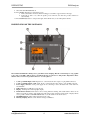
DMX Analyser
DMX512 Tester, Recorder, Repeater
User’s manual
Keep the documents for future reference!
Rev 2 – 18/09/2009.
DEZELECTRIC
DMX Analyser
INTRODUCTION .................................................................................................................................................3
INSTALLATION...................................................................................................................................................3
SOFTWARE UPDATE .........................................................................................................................................3
PRESENTATION OF THE CONTROLLS ........................................................................................................4
INFORMATIONS OF THE DISPALY ...............................................................................................................5
MENU SYSTEM....................................................................................................................................................5
THE MENU SYSTEM ..........................................................................................................................................6
1. MENU – DMX TEST ........................................................................................................................................6
1.1. DMX TEST – PARAMETERS......................................................................................................................6
1.2. DMX TEST – DATA ......................................................................................................................................7
1.3. DMX TEST – FLICKER FINDER ...............................................................................................................8
2. MENU – DMX RECORD .................................................................................................................................8
2.1. DMX RECORD – RECORDING..................................................................................................................8
2.2. DMX RECORD – USB DATA STORAGES ................................................................................................9
3. MENU – DMX SEND ........................................................................................................................................9
3.1. DMX SEND – MANUAL ...............................................................................................................................9
3.2. DMX SEND – FROM USB DATA STORAGE..........................................................................................10
3.3. DMX SEND – INPUT RESEND TO OUTPUT .........................................................................................11
4. MENU – DMX CABLE ...................................................................................................................................11
4.1. DMX CABLE – TEST..................................................................................................................................11
4.2. DMX CABLE – IDENTIFY.........................................................................................................................12
5. MENU –SETUP ...............................................................................................................................................12
5.1. SETUP – LANGUAGE ................................................................................................................................12
5.2. SETUP – DISPLAY......................................................................................................................................13
5.3. SETUP – DATE, TIME................................................................................................................................13
5.4. SETUP – INFORMATIONS........................................................................................................................14
TECHNICAL SPECIFICATIONS ....................................................................................................................15
CONNECTORS AND THEIR LINKING .........................................................................................................15
DIMENSIONS AND WEIGHT..........................................................................................................................15
ACESSORIES ......................................................................................................................................................15
[email protected]
2
www.dezelectric.hu
DMX Analyser
DEZELECTRIC
INTRODUCTION
The DMX Analyser is able to analyze the parameters of DMX signal. It can be analyze analogue and also digital
parameters. Besides we can check DMX cables, and can be possible to record DMX signals to pendrive or to any kind
of USB mass storage device, and can be play back.
For the use of the product it is essential to read through the operating instructions and simultaneously operate the
product. If you have any question, contact the factory or the dealer by e-mail. Here you can report the possible remarks
and recommendations experienced by you. We answer your questions by e-mail or upload the software developed by
you, from where you can download or install the newer version, since the software of the controller can be updated free
of charge. If you would like to find out the freshness of the software of your controller, enter the menu, select the menu
item INFORMATION. Upon logging on the version number of the software of the controller and the date of placing on
the market can be read in the display. Compare the version number with the software version number that can be found
in the website of the manufacturer or the dealer, and if necessary, update the controller software by means of those
described in the SOFTWARE UPDATE section.
INSTALLATION
The product also works with accumulators, so without extern powers supply also possible to use it. Of course the
capacity of accumulators is not endless, so must be loaded before being empty. The loading of accumulators process is
simply can be start of connecting extern power supply.
Switch on the product by pressing POWER (F4) button. On the display you can see the welcome screen and after three
seconds the main menu appears.
If the loading level of accumulator’s critically low and power supply is not connected, then you can read a warning
message on the display. After 5 seconds the product switched off automatically.
If after turning on the caption ’Insert a USB drive containing a valid update file’ is shown in the display, the controller
will be usable only after updating the software. It may occur if the connection is cut off during the software update or
power failure takes place, so the update is interrupted.
Turning off the appliance: in any mode it is possible by pushing POWER (F4) button for 3 seconds. If we use it without
power supply the product switched off automatically in five minutes after last button push.
SOFTWARE UPDATE
The software of DMX Analyzer can be updated by the user to newer versions. The software update can be made with
using of USB mass storage device. Please make this commands step by step to make a successfully update.
1.
2.
3.
4.
5.
6.
7.
8.
You will be need:
a. Except DMX Analyzer a computer which has USB socket
b. USB Mass storage device. It is mainly a pendrive but also able to use Winchester with USB
connection socket. Etc.
c. Update file, it consist of the software for the product. Its name can be: DMX Analyzer v16, for
example. The last two characters in the file name refer to version number. The file can be found on the
homepage of distributor or manufacturer.
Copy the file to pendrive
Switch off DMX Analyzer (if not this case) by pressing POWER (F4) for 3 sec.
Connect power supply to DMX Analyzer (if not this case)
Press F1 and UP buttons and hold them pressed.
Press POWER (F4) button (of course the other two pressed yet: F1 and UP)
The product switched on and the boot loader will start. Let buttons free.
Connect the pendrive to product. On the display you can see the list of files in pendrive.
www.dezelectric.hu
3
[email protected]
DEZELECTRIC
DMX Analyser
9. Select file with UP-DOWN buttons
10. Press START (F4) button to start update process.
a. If the selected file is incorrect, then the loading process will be stopped with error message.
b. If the file is able to use, then the update process will run, and after the product switched of
automatically.
11. Press POWER (F4) button to start product again, and it will be ready to use with updated software.
PRESENTATION OF THE CONTROLLS
The standard of DMX-512 is fixing to use 5 pole XLR sockets and plugs. But all over the Europe is very popular
to use only 3 pole XLR-s. This is why we assembled both type of connectors to this product. Important to know
that the same sex sockets are parallel connected – of course pins 1-3!
1.
2.
3.
4.
5.
6.
7.
8.
5, and 3 pole DMX inputs: DMX input, the two socket means the same output, 1-3 pin parallel connected.
5, and 3 pole DMX outputs: DMX output, the two socket means the same output, 1-3 pin parallel connected.
Power supply connector: extern power supply can be connecting to device. It must be AC or DC with 12V,
and 1200 mA!
USB Connector: for USB mass storage devices.
Display: 128x64 pixel resolution graphic display
F1-F4 function buttons: This buttons can be having different meaning. The actual function name can be
always reed in the footer line of the display. By make long pressing of F3 the actual content of display will be
save to pendrive in file format BMP. With F4 button you can switch on and off the device.
UP-DOWN buttons: Value setting and parameter choosing.
Housing clamping: Must be screw off before change accumulators.
[email protected]
4
www.dezelectric.hu
DMX Analyser
DEZELECTRIC
INFORMATIONS OF THE DISPALY
A. Header
B. Main part
C. Footer
The header and the footer always consist of the same information; it doesn’t depend on which mode is active. The main
part of the display is always changing, and can be see different information in every menu.
1.
Time
The exact time is important to know if we save file to pendrive. The file will be saved with the settled time.
2.
DMX data stream
this icon is the device. If on the left side there is a small x, then it doesn’t come any DMX signal to input, if
there is a small arrow, it means that the is input DMX at the moment. It is also true for right side as output.
3.
Accumulator charging
Accumulator level or charging level icon. If all the three line can be see than the accumulator is charged. If less
then three can be see than it is necessary to charge the accumulator by connecting power supply. If the lines are
appear one after other, and then the accumulator is charging at the moment.
4.
DMX termination
the device can terminate its DMX input by 120ohm resistance, or can be connect the input to output directly by
relays. If there is a 120 written to this icon, then the input is terminated. If there are two connectors with an
array then the in and output are connected.
5.
Actual button function names and warning messages.
Always consist of actual function names for buttons, and appears warning messages.
MENU SYSTEM
You can reach the functions over menu system. After switching on the device we will go to menu. By UP-DOWN
buttons can be select menus, and by pressing F4 can be enter to menu. From submenu you can back by pressing F3
button.
www.dezelectric.hu
5
[email protected]
DEZELECTRIC
DMX Analyser
THE MENU SYSTEM
1.
4.2. Cable identification
DMX TEST
1.1. Parameters
1.2. Data
1.3. Flicker finder
2.
DMX RECORD
2.1. DMX Record
2.2. File delete
3.
DMX SEND
3.1. By manual
3.2. From USB Data storage
3.3. Input resend
4.
CABLE
4.1. Cable test
5.
SETUP
5.1. Display
5.1.1. Backlight
5.1.2. Contrast
5.1.3. Auto timing
5.2. Date, Time
5.2.1. Date,
5.2.2. Time
5.2.3. Format
5.3. Information’s
5.3.1. Version number
5.3.2. Production date
5.3.3. Work time counter
1. MENU – DMX TEST
One of the main functions is testing DMX signal. The device can measure and test analogue and digital parameters of
the incoming DMX signal.
1.1. DMX TEST – PARAMETERS
Display parameters of the incoming DMX signal
REF – REFRESH RATE – refresh rate of dmx packet
BRK – BREAK - break length
MAB – MARK AFTER BREAK - mark after break length
CHR – CHARACTER – distance between data bytes
BTS – BYTES – number of bytes in a packet
In column ACT can be read the actual measured values. In column MIN can be read the less measured values. In
column MAX can be read the highest measured values.
By pressing DELETE (F4) button the MIN and MAX column data can be initialized to actual values.
If there is some failures in measured parameters, then next to the parameter name will be appear a ‘*’.
The failures details can be read after pressing PAGE (F1) button. If there is any difference between measured signal and
the dmx norms, here will be messages to read. If there is more than 4 message then you can page by UP and DOWN
buttons. By pressing DELETE button the error list well be deleted.
[email protected]
6
www.dezelectric.hu
DMX Analyser
DEZELECTRIC
Possible warnings and failure messages:
NO DIGITAL INPUT
There is no signal level changing on the line
NO DMX SIGNAL
There is digital information on the line but can not be analysed as DMX signal
BREAK TOO SHORT
BREAK signal sorter then standard time.
MARK AFTER BREAK TOO SHORT
Mark after break signal sorter then standard time.
FRAMING ERROR
Stop bit is not presented or shorter than standard.
MISSING STOP BIT
The second STOP bit missing
BAUD RATE ERROR
The data transfer speed is out of standard (250Kbit/s), the difference is greater than 5%.
EMPTY PACKET
There is no data byte in the package, it consist only BREAK and MAB information.
TOO MANY DATA BYTES
More than 512 data byte sin the package
BROKEN BYTE
Byte error, missed stop bits before BREAK.
NOISY SIGNAL
Too fast signal polarity changes on the line
1.2. DMX TEST – DATA
Displaying the incoming DMX data.
STARTBYTE: the actual start byte value of received DMX signal.
DMX SIGNAL: Status of the incoming DMX signal.
No: There is no incoming DMX signal
Yes: There is incoming DMX signal
ERROR: There is incoming digital data, but with errors.
FORMAT: the actual data format
www.dezelectric.hu
7
[email protected]
DEZELECTRIC
DMX Analyser
The other part of the display you can read data information. At same time twelve data can be appear with its ordinal
number.
By UP-DOWN you can change channel ordinal number.
By FORM (F2) button you can change data format. Next possibilities can be choosing:
DEC – decimal, scale ten, in range 0-255.
HEX – hexadecimal, scale sixteen, in range 0-FF.
% - percent, in range 0-100.
BAR – barograph, for fast signal value changing.
The failures details can be read after pressing PAGE (F1) button. If there is any difference between measured signal and
the dmx norms, here will be messages to read. If there is more than 4 message then you can page by UP and DOWN
buttons. By pressing DELETE button the error list well be deleted.
1.3. DMX TEST – FLICKER FINDER
Find flickers on data values. You can save the dmx package from incoming signal, so the product save all data value in
actual package. After taken sample the product write all channel number with value which changed.
Until you doesn’t take sample, then the ’ No stored sample ’ message can be read on the display. By pressing SAMPLE
(F4 ) button you can take sample. If there is no incoming signal then sample can not be make.
After taking sample the product will start to compare the actual incoming data with stored sample values. All changed
bytes will be appear on the display.
Act
Fst
Ref
Actual – Actual data
First – First value after changing
Reference – Sample value
On the row header you can read channel values. The channel values appear incremental order.
At same time 5 data can be see on the screen, you can select other pages by pressing UP and DOWN buttons
By pressing SAMPLE (F4) you can take new sample and the data screen will be initialized.
2. MENU – DMX RECORD
The incoming DMX signal can be stored to USB data storage.
Important to know, that all data and parameters of the incoming signal will saved! It means that the device can process
also the fastest DMX rate. If the refresh rate is 44Hz, and 512 byte comes by every package, the DMX Analyser also
can save all data and parameters. If you play the saved stream, you will be the same events on lighting machines as
under recording!
There are different type and quality of pendrive. Some of them – especially old types – works quiet slow, and can save
not the required speed. In this case the device will inform the user that the USB data storage to slow.
2.1. DMX RECORD – RECORDING
UP-DOWN (F4) buttons: select recording row.
[email protected]
8
www.dezelectric.hu
DMX Analyser
DEZELECTRIC
Press ENTER (F4) to go to RECORDING menu.
The device will ask the name of the file.
Select a character by UP-DOWN button.
You can select other cursor position by pressing LEFT (F1) and RIGHT (F2) button
If the name is ready press ENTER (F4) to start recording.
The recording will stop if there is not enough space on the data storage or the user press STOP (F1).
If there is no incoming DMX signal the recording process will not begin to save.
The recordable DMX data and time:
64 Mb
128 Mb
256 Mb
1 Gb
2 Gb
50 min
100 min
3 hour
12 hour
24 hour
2.2. DMX RECORD – USB DATA STORAGES
In this menu you can list of files in USB data storage. Also possible to delete files if it is necessary. May be the user
want to save DMX stream but there is not enough free place on the drive. Then easy to use this deletes function.
3. MENU – DMX SEND
The device can send own DMX signal in this menu.
3.1. DMX SEND – MANUAL
DMX signal can be sending by selected parameters and selected data values.
Send: Auto / Hand
The DMX packets can be send by pressing button, this is hand type. The auto select the signal will be send
continuously.
Timing:
All dmx timing parameter can selected in this menu.
Number of bytes: 1 - 512
The selected number of bytes will be transmitted on the dmx line. Press ENTER (F4) to edit this value. By UP-DOWN
you can change its value and by pressing LEFT-RIGHT you can select the columns.
Data:
The channel values can be edited in this section.
In Hand mode ton DMX packet can be send by pressing SEND (F1). In auto mode the DMX can be start send by
pressing START (F1).
www.dezelectric.hu
9
[email protected]
DEZELECTRIC
DMX Analyser
3.2. DMX SEND – FROM USB DATA STORAGE
DMX data can be sending to output form USB data storage, which was earlier saved to file with this device.
If there is no USB data storage connected, then you can read: No data storage, in this case data can not be send.
.
File
Select ‘File’ by UP-DOWN button
Press SELECT (F4) to go to file selection menu.
Select file with UP-DOWN button.
Press SELECT (F4) button to select file for sending
Timing
The sending DMX packet timing can be selected. At recording not only DMX data saved to file but also the timing
parameters (packet time, break length, mark after break length, character distance). The files can be play with recorded
timing, or also possible to select norms timing, or user defined timings.
Select by UP-DOWN buttons the Timing row.
Press SELECT (F4) to go to timing selection submenu.
Select by UP-DOWN button the timing you wish
Selectable timings:
•
•
•
•
•
•
•
From file
DMX512-A
DMX512/90
DMX512/86
Own1
Own2
Own3
- at recording saved timing data
- BREAK: 176us, MAB: 12us
- BREAK: 88us, MAB: 8us
- BREAK: 88us, MAB: 4us
- user configurable parameters 1
- user configurable parameters 2
- user configurable parameters 3
In Own1, 2, 3 also possible to press DETAIL (F2), and set all parameters after user wish.
By pressing SELECT (F4) you can set selected timing and go back from submenu
Sending
By UP-Down buttons select the Send row.
By pressing SELECT (F4) you can choose two possibilities: auto or hand
Hand:
It will be from DMX stream only one packet after starting it. You must press START (F1) always to send one
package.
Auto:
The packet of DMX stream will send automatically with user selected timing parameters.
[email protected]
10
www.dezelectric.hu
DMX Analyser
DEZELECTRIC
Repeat
By UP-Down buttons select the Repeat row.
By pressing SELECT (F4) you can choose two possibilities: yes or no
No
The DMX data stream will be played only once. If it reaches the end of file then the sending will
stopped. You have to press again to start playing stream again.
Yes
The DMX data stream will be played more times, till user press STOP (F1) button. If it reaches end of
the file, it will automatically play the file again.
Starting DMX Data stream
After select file and set parameters press START (F1) button. The file will start to send to DMX output by the user
selected parameters.
3.3. DMX SEND – INPUT RESEND TO OUTPUT
The incoming DMX signal can be resend to output in this menu. So the device can be used as a DMX power, and also
able to use a wrong but translatable signal to renewing and sending.
MODIFY (F4) – timing selection, and parameter of dmx timing can be edited in this section.
DMX512-A
DMX512/1990
DMX512/1986
Own1
Own2
Own3
In the row of Own1,2,3 you can also push DETAIL (F2) button to open and edit and details of timing data.
START (F1) – starting resend the incoming DMX signal..
On the screen you can see the received and resent package number, and also the number of dropped packages.
Take notice, if on the input signal refresh rate greater then the selected output timings, then sometimes one package will
be dropped, because more packages comes same time as many can resend.
4. MENU – DMX CABLE
The device except analogue and digital signal testing also able test DMX cables. This function can be a huge help to
find wrong cables.
4.1. DMX CABLE – TEST
The device has 5 and 3 pole DMX sockets. But the first three pin are parallel connected. So you can test also 5 and 3
pole DMX cables.
The testing method has two parts. It looks for shorted wires and looked for broken wires. One side of the cable it send
signal to each pin, and on the opposite side the device measure the pins. So the device can diagnose which wire are
broken and which are shorted.
www.dezelectric.hu
11
[email protected]
DEZELECTRIC
DMX Analyser
By pressing PIN 3/5 (F1) you can select the type of DMX cable. It can be 3 or 5 pole.
Connect one end of cable to input and the other end to the output.
The cable test will process automatically. Under connecting method the can be some flicker event, so after connecting
press DELETE (F4) button. This process will delete all failure messages.
On the display you can see which wire is good, and which is wrong. The device will draw a line between shorted pins.
If only opposite pins are shorted, than the cable is good.
On the left side there is a good cable and on the right side the wire 1 and 3 are sorted.
4.2. DMX CABLE – IDENTIFY
The tester can identify if a single connected DMX cable pins are shorted or terminated. This function works with pin 13.
This function is able to identify cables. If you have more a long cable, then one of cable end connect to tester. The other
end of cables selects one and make short circuit. If you can see the event on the screen than you have found the same
cable.
5. MENU –SETUP
5.1. SETUP – LANGUAGE
The device can be write text to display in different languages
[email protected]
12
www.dezelectric.hu
DMX Analyser
DEZELECTRIC
UP-DOWN: select language
SELECT (F4): the selected language will be activated and goes back to menu.
After switching on the device for three seconds the welcome message can be see. Under this time also possible to select
language by F1, F2 and F3 button.
5.2. SETUP – DISPLAY
Some display parameter can be set in this menu.
By UP-DOWN button you can select between contrast, backlight or auto switch of timing.
Contrast
By F1 and F2 you can set the contrast parameter. The contrast can be change depend of environment temperature, this is
why can be need to this function.
Press ENTER (F4) to save this parameter.
Backlight
By F1 and F2 you can select backlight parameter. Backlight is important because the device has accumulator and the
power consumption of the display is quiet high. So you can save energy and use the device longer time from
accumulator if you set the backlight power to low level.
Press ENTER (F4) to save this parameter.
Auto switch off
More energy can be saved with this parameter. Here you can select a time. After last button press the device will
automatically switch off the backlight if this time is over.
By F1 and F2 select a time. There is 5sec step between each parameter. If you select 0 sec, then the backlight will never
lit. If you select ‘---’, then the backlight will not switch off automatically.
5.3. SETUP – DATE, TIME
Here you can set the date and time parameters.
Date
www.dezelectric.hu
13
[email protected]
DEZELECTRIC
DMX Analyser
Press ENTER (F4) to go to datum settings. By PREW (F1) and NEXT (F2) you can select among year, month and day
parameters. By UP-DOWN you can change the actual parameter value.
Press ENTER (F4) to save this parameter.
Time
Press ENTER (F4) to go to time settings. By PREW (F1) and NEXT (F2) you can select among hour, min and sec
parameters. By UP-DOWN you can change the actual parameter value.
Press ENTER (F4) to save this parameter.
Customize
It is possible to customize the date and time format. By pressing
UP-DOWN button you can select among date format, date separator
or time format.
Date format
PREW (F1 and NEXT (F2) for select date format
YEAR. MONTH. DAY.
DAY. MONTH. YEAR. MONTH. NAP. YEAR
Date separator
PREW (F1 and NEXT (F2) for select date separator character.
’.’
’/’
Time format
PREW (F1 and NEXT (F2) for select time format
12h
24h
Press ENTER (F4) to save all this parameters.
5.4. SETUP – INFORMATIONS
The device information can be read in this menu.
[email protected]
14
www.dezelectric.hu
DMX Analyser
DEZELECTRIC
Technical specifications
•
•
•
•
Accumulator capcity:
Incoming DMX signal level:
USB data storage max. size
DMX digital level accuracy
2db, 1,5mAh, 6 hours work time with one charge
-10 / +15V, 20mV-os sensibility
2Gb
200ns
Connectors and their linking
DMX connector:
Two piece of input. One of them with 3 poles, and the other is with 5 poles. The first three pins are parallel connected.
Two piece of output. One of them with 3 poles, and the other is with 5 poles. The first three pins are parallel connected.
Power supply: The controller can be operated from a power supply of AC and DC types; therefore the
linking is not sensitive to polarity. The controller should be operated only from such a power supply, which is
of 12 voltages and can be loaded with at least 1200mA.
USB connector:
For external data saving and loading. Any type of USB data storage can be connected up to 2GB
capacity. File systems: FAT16, or FAT32.
Dimensions and weight
• Width(with alu case): 350 mm; Height: 250 mm; Depth: 130 mm
• Weight: 4,1kg
Acessories
• 1pc 230V/12V, AC/DC or AC/AC power supply (min 1200mA)
• 1 pc ALU case
• 1pc user’s manual
www.dezelectric.hu
15
[email protected]