1
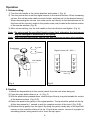
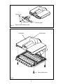
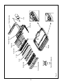
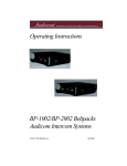
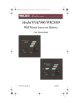
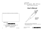
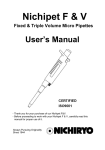
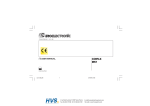
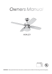
Autoclavable
Nichipet 7000
Multi-channel digital micro pipette
User’s manual
CERTIFIED
ISO9001
9 Thank you for your purchase of our Nichipet 7000.
For safe and proper use of the Nichipet 7000, please be sure to carefully
read this manual. After reading this manual, please keep it in a convenient
place for quick reference.
BE ORIGINATIVE
Always Pursuing Originality
Since 1944
Autoclavable
Nichipet 7000
Multi-channel digital micro pipette
Features
9
9
9
9
9
9
9
9
Complete autoclaving (121°C 20 minutes) is possible with this unit.
Fatigue free operation for long time.
Digital system allows easy one-touch volume setting.
One-touch locking function with single hand.
Covering 0.5 µr to 300 µr range with 4 models each of 8 and 12 channels.
Unit construction design helps to prevent accuracy change due to hand temperature.
Suitable for sampling to a micro plate with 96 well and 9 mm pitch.
Because the handle and casing angle can be adjusted freely (360 degrees), the unit can
be used at a position of your choice.
9 Includes tip eject function. The tips can be removed without touching them by fingers.
9 The simple casing structure enables easy maintenance.
Standard accessories
9 Tip
8 ch ...................... x 16
12 ch ...................... x 24
9 Silicone grease ............... x 1
9 Cleaning wire .................. x 1
9 Wrench ........................... x 1
Please make sure that none of the above accessories are missing before using this unit.
Safety precautions
9 For safe and proper use of the Nichipet 7000, please be sure to carefully read the
“Safety precautions” in this section and “CAUTIONS” on the next page before starting
work with it.
9 The contents of “CAUTIONS” are matters that require the user’s attention, not only for
using the Nichipet 7000 properly, but for preventing the user from accidents and physical
damage.
9 After reading this manual, please keep it in a convenient place for quick reference.
1
Please observe the following cautions to ensure the safe use of this product
CAUTIONS
Be sure to observe the following instructions for using
your Nichipet 7000 properly and safely.
If the user uses the Nichipet 7000 in the wrong way, disregarding the following instructions,
it may result in injury to the user or/and other persons or physical damage to this instrument
or/and other equipment.
1.
2.
3.
4.
5.
6.
7.
8.
9.
10.
11.
12.
13.
Do not use for any other purpose than handling of liquid.
Never modify this instrument, as this may cause an accident.
Do not use for handling of liquids that will be directly injected into the body.
As certain types of liquids are harmful to the body, never discharge any sample liquid
while pointing the instrument at a person
Do not eject tips while this unit is pointed at a person.
Do not eject tips when there is liquid inside.
The sharp protruding tips of the unit are dangerous. Please use care when handling.
Please make sure that the tips are securely attached to the nozzle. Scattering of
liquid will occur if tips fall off the nozzle.
If liquid that is harmful to the body has splashed onto the unit, treat it properly before
using it.
When using liquid that is harmful to the body, never touch a tip that has been used.
Do not use this unit to mix liquid etc. This will cause tips to loosen, fall off, or result
in liquid splashing on the unit.
After autoclaving or drying, do not touch the unit as it is very hot. Touching the unit
could result in bodily harm.
Although this product is designed to resist chemicals, it may be damaged by some
kinds of chemicals such as N-methyl-pyrrolidinone, etc. Please contact the manufacturer
before using special chemicals.
2
Matters that require strict observance
Users are required to strictly observe
the following points in order for
the instrument to keep its excellent precision,
reproducibility and original performance for a long time.
1. Avoid exposing this unit to direct sunlight 2 hours before operation as well as during
operation. Exposure to sunlight may result in loss of accuracy.
2. Avoid touching the tip and nozzle sections as much as possible just before operating.
Warming of these parts may result in loss of accuracy.
3. Please use the forward method when sampling (the operation method used in this manual).
Using a different method may result in loss of accuracy.
4. Press the push button gently. If pressed quickly, liquid will be pulled into the inside of the
unit which may result in loss of accuracy. Liquid inside the unit may also result in
performance loss.
5. Please discard tips after use. Repeated use may result in loss of accuracy. There is also
danger of contamination (✽) caused by mixing of liquids.
✽ Liquid remaining in a tip may be mixed with new liquid suctioned in causing an undesired
result.
6. Do not turn the unit on its side or upside down when there is liquid in the tips. Liquid will
get inside the unit which may result in performance loss.
7. After autoclaving and drying, wait till the unit has cooled down sufficiently before using.
Using while warm may result in loss of accuracy.
8. After autoclaving and drying, assemble the unit after it has cooled down sufficiently.
Assembling while warm may result in damage to screw heads or other forms of product
quality degradation.
9. When turning the push-button, don’t exceed the specified sample volume limit, otherwise
the instrument may be damaged or deteriorate.
10. Do not operate when the liquid amount is less than the set volume. It may cause the liquid
to scatter into the main body and the instrument may deteriorate in the quality.
3
Operation
1. Volume setting
1) Turn the lock handle in the unlock direction and loosen it. (Fig. A)
2) Turn the push button to set the digital counter to the desired volume. When increasing
volume, first set the scale a half revolution further, and then set it to the desired amount.
When decreasing the volume, the scale can be set directly to the desired amount. At
this time set the counter’s scale to the pointer mark (red) located at the bottom section
of the counter window. (Fig. B)
3) After volume setting, turn the lock handle in the lock direction and tighten. (Fig. A).
Note: Do not exceed the specified liquid volume limit, otherwise the instrument
may be damaged or deteriorate in the quality.
Note: After changing the volume, use the unit after first carrying out a trial operation.
Push button
Lock
Digital counter 40∼200 µr
Vo
40 lum
~2 e
00
µl
Unlock
2
0
0
0
4
0
Lock handle
Pointer mark
(Red)
Fig. B
Fig. A
2. Suction
1) Attach the disposable tip to the nozzle (attach from the rack when doing so).
2) Press the push button down to a ~ b. (Fig. C)
3) With the push button pressed down, insert the top of the tip to a point suitable for suction
of the desired volume. (Fig. D-1).
4) Return the push button gently to its original position. The liquid will be pulled into the tip.
At this time pause for 1 second to wait for complete suction of the liquid. (Fig. D-2).
5) Withdraw the tip gently from the liquid. By doing this gently, hardly any of the liquid will
remain on the outside surface of the tip. If liquid does remain, remove it by paper or
something similar, being careful not to touch the tip’s point.
4
Note: Do not carry out suction from the c
position shown in Fig. C. (liquid will be
pulled into the nozzle if done from this
position)
Note: Operate the push button gently.
Releasing quickly will cause liquid to
be pulled into the inside of the unit
causing possible loss of accuracy.
a
b
c
Fig. C
1
2
3
4
5
6
Fig. D
3. Discharge
1) Touch the top of the tip to the inside of the receiving vessel. (Fig. D-3).
2) Gently depress the push button from a to b. Wait abut 1 second, then depress to
the c position. The liquid is now discharged. (Fig. D-4,5).
3) Press the eject button to remove the used tip. (Fig. D-6).
Do not touch the tip during use or after use when liquid that is harmful to the
body is being used.
5
Disassembly and assembly of the airtight unit
If any of the problems included in the “Troubleshooting” section of this manual arise,
use the following procedure to disassemble and inspect this unit.
1. Disassembly
1) Turn the ring in the direction of the arrow and remove the casing from the handle. (Fig. 1)
Note: If the connection screw is loosened, tighten it with the provided wrench. (Fig. 2)
2) Remove the screw that holds the ejector and remove the ejector from the casing. (Fig. 3)
3) Remove the screw that holds the casing. (Fig. 4)
4) Lightly press the nozzle and remove the casing A set as shown in Fig. 4.
5) Remove each part. (Fig. 5)
2. Assembly
1) Attach each part to casing B. (Fig. 5)
2) Assemble and attach the casing A set. (Fig. 4)
3) Assemble and attach the ejector to the assembled casing. (Fig. 3)
4) Assemble and attach the casing set to the handle. (Fig. 1)
Note: When assembling be sure to set the counter to the maximum volume range.
(Parts will not mesh properly)
Note: If the connection screw is loosened, tighten it with the provided wrench. (Fig. 2)
Handle
Handle
Ring
Ring
Casing
Wrench
Connection
washer
Fig. 1
Connection
screw
Fig. 2
6
Ejector set
Flat washer
Ejector plate
Ejector plate holding screw
Fig. 3
Ejector button
Casing Aset
Casing holding screw
Fig. 4
7
8
Fig. 5
Position to gear plungears
Nozzle spring holder
Nozzle spring
Nozzle
X ring
Plunger set
Casing B
X ring holder
Plunger holder set
First spring
Bush
Plunger head spring
Autoclaving
Autoclaving of this complete unit is possible. Follow the procedure below at a temperature of
121° C for 20 minutes.
1) Be sure to loosen the lock handle and set the counter to the maximum volume number
of the volume range.(Fig.A)
2) Loosen a connecting screw in the Fig.2 by 180 degree.
3) Loosen four screws on the casing in the Fig.4 by 180 degree.
4) When placing inside the autoclaving unit, be careful not to damage the nozzle. Also,
place in a position that does not put any weight on the nozzle.
5) After autoclaving, be sure to dry the unit thoroughly.
Drying
Carry out drying immediately after autoclaving. Dry the unit thoroughly in a constant temperature air-drier at 60° C for over 60 minutes.
1) Dry the product in the same condition as when it was autoclaved.
2) Be careful not to damage the nozzle when placing the unit in the dryer. Also make
sure that the unit is placed in a position that does not place any weight on the nozzle.
3) Make sure that the unit turned to the normal temperature after the drying.
Tighten the connecting screw in the Fig.2 and four screws on the casing in the Fig.4.
And make sure that a ring in the Fig.1 is tightened.
Note: After drying, if the unit is assembled while it is still warm, screw head damage
etc., may occur causing damage to the product or loss of product performance.
Be sure to reassemble the unit after it has completely cooled down. Also, using
the product while it is warm may result in loss of accuracy.
Do not touch the unit directly with your hand just after autoclaving and drying,
because the unit is extremely hot during autoclaving and drying. Directly
touching the hot unit may cause an accident.
Code
(Model No.)
Variable range
(µr)
00-NP78V, 12V
0.5 ~ 10
00-NP78S, 12S
00-NP78L, 12L
5 ~ 50
40 ~ 200
00-NP78K,12K
50 ~ 300
Measured volume
(µr)
Accuracy
(%)
Precision
(%)
1 µr
5 µr
±8.0
±4.0
<4.0
<2.0
10 µr
5 µr
±2.0
±3.0
<1.0
<1.5
25 µr
50 µr
±2.0
±1.0
<0.8
<0.5
40 µr
100 µr
±1.4
±1.0
<0.5
<0.4
200 µr
50 µr
±0.9
±1.4
<0.3
<0.7
150 µr
300 µr
±1.0
±0.6
<0.5
<0.2
9
9 Tips (autoclavable)
Code
Volume range
(µr)
BMT-UT
BMT-SE
0.1 ~ 10
5 ~ 200
BMT-K
50 ~ 300
Color
Applicable model
Tip length
Q’ty / bag
Natural 00-NP7-8, 12V
Natural 00-NP7-8,12S / 8, 12L
31.0 mm
51.1 mm
1000
1000
Natural 00-NP7-8,12K
58.9 mm
1000
9 Rack tips (autoclavable)
Code
Volume range
(µr)
Color
BMT-UTR
BMT-SER
0.1 ~ 10
5 ~ 200
Natural
Natural
BMT-KR
50 ~ 300
Natural
Applicable model
Q’ty / box
00-NP7-8,12V
960 (96 x 10 cases)
00-NP7-8, 12S / 8, 12L 960 (96 x 10 cases)
00-NP7-8,12K
10
960 (96 x 10 cases)
RECALIBRATION PROCEDURE
1. Remove the cap by pulling it out with your fingers. (Fig.6)
2. Loosen the lock handle by turning it counter clockwise and stop when the oval opening on
the lock handle faces you. (Fig.7)
3. Rotate the push button until one of two hex head screws can be seen through the oval
opening. (Fig.7)
4. Loosen both hex head screws with a hex head wrench (1.5 mm) by turning them counterclockwise one by one. (Fig.8)
5. Keeping the hex head wrench inserted into one hex head serew, turn the push button to
calibrate the pipette. (Fig.8)
6. The pipetting volume can be adjusted by rotating the push button clockwise to increase and counter-clockwise to decrease. Please refer to the table standard volume
adjustments.
Degree of Rotation
360°
720°
0.5 µr~ 10 µr
0.31 µr
0.63 µr
5 µr~50 µr
1.6 µr
3.2 µr
40 µr~ 200 µr 50 µr~ 300 µr
6.5 µr
9.6 µr
13 µr
19.2 µr
7. Tighten the both hex head screws after adjusting the push button and measure the
accuracy of the pipette.
8. Repeat the above procedures until the pipette is calibrated within the specified accuracy. An accuracy test should be made
at the specified minimum and maximum
volume of each pipette.
Cap
9. Return the cap to its original position.
Fig.6
Push button
A : Increase
B : Decrease
Lock handle
Oval opening
Hex head screw
Hex head
wrench
Fig.8
Fig.7
11
Troubleshooting
Problem
Probable cause
Foreign matter in the
Liquid is not
sucked in.
➡
Remove foreign matter with
provided cleaning wire.
X ring is worn or
damaged.
➡
Replace the “X ring set” with the
new set.
Plunger is damaged or
rusty.
➡
Replace the “X ring set” and
“Plunger set” with the new sets.
➡
Attached tips are loose.
➡
Attach the tips firmly.
➡
Plunger has shifted.
➡
Press the push button a few times.
➡
X ring is damaged.
➡
Replace the “X ring set” with the
new set.
➡
No grease on the
plungers and/or X rings.
➡
Coat the plungers and/or X rings
lightly with the provided grease.
➡ nozzle.
➡
➡
Solution
➡
Liquid leakage
from tip. Nozzle tip attachment
Replace the “nozzle set” with the
➡
➡ new set.
part is damaged. Push button
movement is
poor.
Looseness of
body and casing.
➡
Liquid in the nozzle.
➡
If immediately after suction or if
there just some adherence of liquid,
disassemble and clean the parts.
➡
Ring is loose.
➡
Tighten the ring.
➡
Connection screw is
loose.
➡
Tighten the connection screw
with the provided wrench.
If the problem persists even after the above points have been checked, stop usage of the unit
immediately and consult with the sales outlet where the unit was purchased.
Caution: At this time please confirm that there has been no contamination by chemicals
that are harmful to the human body.
12
9 Replacement parts list (Please specify volume and channel number when ordering).
Replacement part’s name
Contents
Ring
Connection washer
Connection screw
Casing A set
Casing B
Plunger fixing unit set
Plunger head spring Set
☆
Plunger set
☆
X ring suppressor set
Nozzle spring holder set
X ring set
Nozzle set
Nozzle spring set
Casing holding screw
☆
Ejector set
Wrench
☆
☆
x1
x1
x1
Casing A (x 1)
Insert nut (x 5)
Ejector button (x 1)
Ejector shaft A (x 1)
Ejector shaft B (x 1)
Ejector spring (x 1)
x1
Plunger fixing unit (x 1)
First spring (x 2)
Guide shaft (x 2)
Guide tube (x 2)
E ring (x 4)
Bush (x 1)
Stem (x 1)
8ch x 8, 12ch x 12
Plunger (8ch x 8, 12ch x 12)
Plunger head (8ch x 8, 12ch x 12)
X ring suppressor (8ch x 2, 12ch x 3)
Nozzle spring holder (8ch x 2, 12ch x 3)
X ring (8ch x 8, 12ch x 12)
Nozzle (8ch x 8, 12ch x 12)
Nozzle spring (8ch x 8, 12ch x 12)
x4
Ejector plate (x 1)
Flat washer (x 1)
Ejector plate holding screw (x 1)
x1
size
common
common
common
Each volume
Each volume
Each volume
common
Each volume
Each volume
common
Each volume
Each volume
common
common
Each volume
common
Note: Parts marked with a star (☆) influence precision of the product. When replacing these
parts, please replace all of them with new parts.
※ Please contact your local distributor for price information.
※ Specifications of the instruments and optional accessories as well as contents of
accessory sets are subject to change without notice.
※ No part of this manual may be reproduced/reprinted in any form without permission of
the copyright holder. (This is strictly prohibited by the copyright law.)
13
Memo
14
4-10. Iwamoto-cho 2-chome Chiyoda-ku, Tokyo 101-0032, Japan
TEL : 81-3-5820-2664
FAX : 81-3-5820-2410
Homepage URL http://www.nichiryo.co.jp
E-mail
E-01
[email protected]
2004.01 (1000)