1
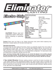
SPECIFICATIONS:
Electro 196 II
CAUTION! Please read and
understand these instructions
before installing or operating
this unit.
Model:
Lamp:
Weight: Size:
Fuse:
Supply Voltage: Working Position:
Duty Cycle:
DMX Channels:
Colors: Warranty: Electro 196 II
L.E.D. (84 Red, 51 Green, and 60 Blue)
2.8lbs./ 1.3kgs.
6.14” (H) x 8.07” (W) x 6.8” (D)
2 Amp
120V
Any Safe position
None 8
Multiple Colors
1 Year
Caution! Never open unit when in use.
Always disconnect main power before
replacing fuse. Remember to always
replace with the exact same type fuse.
Operating Instructions:
The Electro 196 II has been tested at the factory, there is no assembly required. The unit is ready to
be plugged into a power outlet. This unit is a 8 channel DMX intelligent LED par can. It can be run as
a stand-alone unit, DMX controlled unit, or in a Master/Slave configuration. While in Stand Alone or
a Master/Slave configuration, you can run the auto mode, sound active mode, or control the colors
and intensity manually. For stand-alone mode, Master/Slave configuration, and DMX Control see
other side.
1 Year Limited Warranty: Eliminator Lighting warranty is valid from the date of purchase. Our
1 year limited warranty covers manufacturing defects only. Serial number, place of purchase with
dated valid receipt must be submitted at time of service. Eliminator Lighting warranty does not cover
items or parts prone to wear and tear: lamps, fuses, brushes and belts. Eliminator Lighting warranty
is only valid with-in the United States.
©Eliminator® Los Angeles, CA. - www.EliminatorLighting.com
Stand Alone (Manual Mode):
1. Plug the fixture in, dipswitch controls are as follows: Dipswitch 1 is Red, Dipswitch 2 is Green, Dipswitch 3 is Blue, Dipswitch 4 is Yellow, Dipswitch 5 is Navy Blue, Dipswitch 6 is Purple, and Dipswitch 10 will change between Red, Green, and Blue.
2. When dipswitches 1, 2, 3, 4, 5, 6, or 10 are ON, dipswitches 7, 8, and 9 will control the intensity.
Stand Alone (Auto Mode):
1. Plug the fixture in and use dipswitches 7, 8, and 9 to run Auto Mode and control the intensity.
Stand Alone (Sound Active Mode):
1. When all dipswitches are OFF, the fixture will run in Sound Active Mode.
Master-Slave Operation (Auto Mode or Sound Active): This function will allow you to link up to 16
units together and operate without a controller. In Master-Slave operation one unit will act as the controlling unit and the others will react to the controlling units operation. Any unit can act as a Master or
as a Slave.
1. Using standard XLR microphone cables, daisy chain your units together via the XLR connector on
the rear of the units. Remember the Male XLR connector is the input and the Female XLR con nector is the output. For longer cable runs we suggest a terminator at the last fixture.
2. The dipswitch settings for Master/Slave mode is as follows. For Sound Active mode the Master unit must have all dipswitches in the “Off” position, and the slave units, dipswitch 1 “On”.
For Auto Mode the Master unit must have dipswitch 10 “On”, and the slave units, dipswitch 1 “On”.
Universal DMX Control: This unit allows you to use any universal DMX-512 controller to control the
different DMX traits. A DMX controller allows you to create unique programs tailored to your individual needs.
1. The Electro 196 II II uses eight DMX channels.
2. To control your fixture in DMX mode, follow the set-up specifications that are included with your DMX controller.
3. Set your desired DMX address using the dipswitches.
4. Use the controller’s faders to control the various DMX fixture traits.
5. For longer cable runs (more than a 100 feet) use a terminator on the last fixture.
6. For help operating in DMX mode consult the manual included with your DMX controller.
DMX TRAITS:
CHANNEL 1: STROBING & MODES
0 - 1 =
OPEN
2 - 99 =
STROBING SLOW - FAST
100 - 127 = CLOSED
128 - 191 = AUTO MODE SLOW - FAST
192 - 255 = SOUND ACTIVE SLOW - FAST
CHANNEL 2: RED LED’S GROUP 1
0 - 255 = INTENSITY 0% - 100%
CHANNEL 3: RED LED’S GROUP 2
0 - 255 = INTENSITY 0% - 100%
CHANNEL 4: RED LED’S GROUP 3
0 - 255 = INTENSITY 0% - 100%
CHANNEL 5: GREEN LED’S GROUP 1
0 - 255 = INTENSITY 0% - 100%
CHANNEL 6: GREEN LED’S GROUP 2
0 - 255 = INTENSITY 0% - 100%
CHANNEL 7: BLUE LED’S GROUP 1
0 - 255 = INTENSITY 0% - 100%
CHANNEL 8: BLUE LED’S GROUP 2
0 - 255 = INTENSITY 0% - 100%
When Channel 1 is between the values of 100 - 255, all other channels will not work. To use channels 2 - 8, channel 1 either has to be off or strobing (values 2 -99).
©Eliminator® Los Angeles, CA. - www.EliminatorLighting.com