1
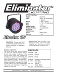
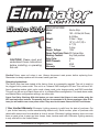
Electro Strip
CAUTION! Please read and
understand these instructions
before installing or operating
this unit.
SPECIFICATIONS:
Model: Electro Strip
LEDs:192 - 64 Red, 64 Green, & 64 Blue
Weight: 3.3lbs./ 1.5kgs.
Size:
19” (L) x 3.8” (W) x
5.1” (H)
Fuse:2 Amp
Supply Voltage: 120V
Power Cord Daisy Chain:33 Fixtures Max.
Working Position:
Any Safe position
Duty Cycle:
None DMX Channels:
4
Colors: RGB
Warranty: 1 Year
Caution! Never open unit when in use. Always disconnect main power before replacing fuse.
Remember to always replace with the exact same type fuse.
Operating Instructions:
The Electro Strip has been tested at the factory, there is no assembly required. The unit is ready to
be plugged into a power outlet. This unit is a 4 channel DMX intelligent LED bar. This unit has 4 different operating modes; static color mode, chase mode, color change mode, and DMX controlled.
This unit can be run as a Stand Alone unit or in a Master/Slave configuration. For stand-alone mode,
and Master/Slave configuration settings, see other side.
Power Cord Daisy Chaining: With this feature you can connect the fixtures to one another using the
IEC input and output sockets. The quantity that can be connected is 33 fixtures maximum. After 33 fixtures you will need to use a new power outlet. They must be the same fixtures. DO NOT mix fixtures.
1 Year Limited Warranty: Eliminator Lighting warranty is valid from the date of purchase. Our
1 year limited warranty covers manufacturing defects only. Serial number, place of purchase with
dated valid receipt must be submitted at time of service. Eliminator Lighting warranty does not cover
items or parts prone to wear and tear: lamps, fuses, brushes and belts. Eliminator Lighting warranty
is only valid with-in the United States.
©Eliminator® Los Angeles, CA. - www.EliminatorLighting.com
SdAd - Universal DMX Control - DMX Address Setting. This unit allows you to use any univer-
sal DMX-512 controller to LED color and the shutter (strobe). A DMX controller allows you to create unique
programs tailored to your individual needs. Follow the set-up specifications that are included with your DMX
controller.
1. When “SYS” is displayed, press the ENTER button so that “SdAd” is displayed, then press ENTER again.
2. The current address should be displayed. Use the UP or DOWN buttons to find your desired address. Press
ENTER to set your desired DMX address. Now connect your DMX Controller.
3. Use the controller’s faders to control the various DMX fixture traits.
4. For longer cable runs (more than a 100 feet) use a terminator on the last fixture.
5. For help operating in DMX mode consult the manual included with your DMX controller.
A000 - in this mode you can choose one of 23 working modes; 7 static colors with flash, 6
color change modes with adjustable change speed, 7 chase sequences with adjustable chase
speed, adjust able RGB mode, color fade mode with adjustable fade speed, and sound active
mode. The next few sections will detail the working modes.
1. Press the MENU button until you are at the beginning of the system menu. You will know you are at the
beginning when “SYS” is displayed. If “SYS” is displayed press either the UP or DOWN button so that “ACt”
is displayed. When “ACt” is displayed press ENTER. “AXXX” will be displayed, “XXX” represents the displayed
mode.
2. Now using the UP and DOWN buttons scroll through the various programs. See the next four sections for
detailed descriptions of the various working modes. To exit from a mode press the MODE button.
A001 - A007 - there are 7 static colors that can be projected. Flash (strobe) can be added to
your desired color.
1. Once you have followed the directions listed under section “A000” you can now select and run different
programs.
2. A001 - A007 are your static color modes. Each number 1-7 represents a different color.
3. Press the UP and DOWN buttons to scroll through the different colors. Once you have found your desired
color just leave the setting as is. If you would like to add strobing to the color press ENTER, “F.000” will be
displayed. Press the UP or DOWN buttons to adjust the strobing speed. Once you have found your desired
speed press the MODE button once to go back to your color mode. To exit the running modes completely
press the MODE button twice.
A008 - A013 - there are 6 color changing programs to choose from. The speed of the color
change is adjustable in all 6 programs. Flash (strobe) can be added to programs A008 - A011.
1. Once you have followed the directions listed under section “A000” you can now select and run different
color changing programs.
2. A008 - A013 are your color changing programs. Each number 8-13 represents a different color changing
program.
3. Press the UP and DOWN buttons to scroll through the different programs. Once you have found your
desired program press ENTER. “P.XXX” will be displayed, this is program speed adjustment. Use the UP or
DOWN buttons to adjust the speed of the color change. Once you have found your desired color change
speed you can leave the unit as is or press MODE so that your selected program number is displayed. This
mode can also be run by sound activity, adjust the sensitivity knob located on the rear to make the unit more
senstive or less sensitive to sound. Turning the knob clockwise makes it the more sensitive, counter-clockwis
makes it less sensitive.
©Eliminator® Los Angeles, CA. - www.EliminatorLighting.com
4. If you would like to add strobing to the color change program, press ENTER after you have set the color
change speed, “F.000” will now be displayed. Press the UP or DOWN buttons to adjust the strobing speed.
Once you have found your desired speed press the MODE button twice to go back to your color change program.
4. To exit the running modes completely, press the MODE button three times.
A014 - A020 - there are 7 color chases to choose from. The speed of the chase is adjustable
in all 7 chases. Flash (strobe) is not available for these chases.
1. Once you have followed the directions listed under section “A000” you can now select and run different
color chase programs.
2. A014 - A020 are your color chase programs. Each number 14-20 represents a different color chase program.
3. Press the UP and DOWN buttons to scroll through the different chases. Once you have found your desired
chase press ENTER. “P.XXX” will be displayed, this is chase speed adjustment. Use the UP or DOWN buttons
to adjust the speed of the color chase. Once you have found your desired color chase speed you can leave
the unit as is or press MENU so that your selected program number is displayed. This mode can also be run
by sound activity, adjust the sensitivity knob located on the rear to make the unit more senstive or less sensitive to sound. Turning the knob clockwise makes it the more sensitive, counter-clockwis makes it less sensitive.
4. To exit the running modes completely press MENU three times.
A021 - in this mode you can control manually control the RGB colors.
1. Once you have followed the directions listed under section “A000” you can now manually adjust the RGB
colors to create your own desirable static color.
2. A021 is your RGB mode. When A021 is displayed press ENTER. “P.XXX” will be displayed, this is the Red
adjustment. Use the UP and DOWN buttons to adjust the intensity of Red. Once you have found your desired
intensity press ENTER.
3. When you press ENTER after adjusting the Red color, “F.XXX” will be displayed. This is the Green intensity adjustment. Use the UP and DOWN buttons to adjust the intensity of Green. Once you have found your
desired intensity press ENTER.
4. When you press ENTER after adjusting the Green color, “C.XXX” will be displayed. This is the Blue intensity
adjustment. Use the UP and DOWN buttons to adjust the intensity of Blue. Once you have found your desired
intensity press ENTER.
3. Continue to adjust the colors until you produce your desired color. Once you have made your desired color
leave the unit as is. To exit the RGB mode completely press the MODE button.
Master-Slave Configuration:
This function will allows you to link units together to run in a Master-Slave mode. In Master-Slave operation
one unit will act as the controlling unit and the others will react to the controlling units built-in programs. Any
unit can act as a Master or as a Slave however, only one unit can be programmed to act as the “Master.”
1. Daisy chain your units via the XLR connector on the rear of the unit. Use standard XLR microphone cables
to link your units together. Remember that the Male XLR connector is the input and the Female XLR connector is the output. The first unit in the chain (master) will use the female XLR connector only. The last unit in the
chain will use the male XLR connector only.
2. Using the Master unit, choose your desired operating mode and connect the “Slave” unit or units.
3. Turn “On” all of the slave units first, then turn “On” the Master unit last. All slave units will automatically
sync to the Master unit.
©Eliminator® Los Angeles, CA. - www.EliminatorLighting.com
DMX TRAITS:
CHANNEL 2: CHANGE/CHASE/FADE SPEED &
CHANNEL 1: COLORS: STATIC/CHANGING/
CHASES/RGB COLOR MIX/CHASE FADE/AUTO RED DIMMER
(PLEASE SEE NOTES BELOW)
RUN
0 - 127 = COLOR CHANGE & CHASE SPEED
0 - 9 = BLACKOUT
SLOW - FAST
10 - 19 = RED
128 - 255 SOUND ACTIVE
20 - 29 = GREEN
30 - 39 = BLUE
40 - 49 = YELLOW
50 - 59 = MAGENTA
60 - 69 = CYAN
70 - 79 = WHITE
80 - 89 = COLOR CHANGE 1
90 - 99 = COLOR CHANGE 2
100 -109 = COLOR CHANGE 3
110 - 119 = COLOR CHANGE 4
120 - 129 = COLOR CHANGE 5
130 - 139 = COLOR CHANGE 6
140 - 149 = COLOR CHASE 1
150 - 159 = COLOR CHASE 2
160 - 169 = COLOR CHASE 3
170 - 179 = COLOR CHASE 4
180 - 189 = COLOR CHASE 5
190 - 199 = COLOR CHASE 6
200 - 209 = COLOR CHASE 7
210 - 219 = RGB COLOR MIX
220 - 229 = CHASE FADE
230 - 255 = SOUND ACTIVE AUTO RUN
0 - 255 = RED DIMMER
0 - 255 = FADE SPEED SLOW - FAST
CHANNEL 3: STROBING & GREEN DIMMER
(PLEASE SEE NOTES BELOW)
0 - 249 =
STROBING SLOW - FAST
250 - 255 = SOUND ACTIVE
0 - 255 = GREEN DIMMER
CHANNEL 4: BLUE DIMMER
0 - 255 = BLUE 0% - 100%
NOTES:
When the Channel 1 values are between 80 - 209, Channel 2 will control the speed and channel will
control strobe.
When Channel 1 values are between 210 - 219 (RGB COLOR MIX) Channel 2 will control Red, Channel 3 will control Green, and Channel 4 will control Blue.
When Channel 1 values are between 220 - 229 (CHASE FADE), Channel 2 will control the Fade
Speed.
When Channel 1 values are between 10 - 79, Channel 3 will control the Stobing.
©Eliminator® Los Angeles, CA. - www.EliminatorLighting.com