1
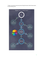
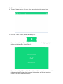
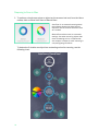
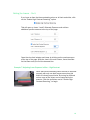
Matter and Form
3D Scanner
User Manual
Table of Contents
Our Roots ................................................................................................................................................. 2
Legal & Safety Stuff ................................................................................................................................. 3
Laser Stuff ........................................................................................................................................... 4
Inside the Box .......................................................................................................................................... 5
Getting Started ............................................................................................................................... 6
Connecting the Scanner .......................................................................................................................... 7
Using the Software .................................................................................................................................. 8
Calibrating the Scanner........................................................................................................................... 9
Preparing to Scan in Windows .......................................................................................................... 12
Preparing to Scan in Mac.................................................................................................................. 16
Rotating, Zooming In and Panning ....................................................................................................... 20
Doing More with the Scanner ......................................................................................................21
Saving and Exporting a Scan ................................................................................................................ 22
Cleaning a Scan ..................................................................................................................................... 23
Cleaning Scans in Windows .............................................................................................................. 23
Cleaning Scans in Mac...................................................................................................................... 27
Auto Clean .................................................................................................................................................... 28
Layers ............................................................................................................................................................ 29
Cropping ........................................................................................................................................................ 30
Brush Cleaning ............................................................................................................................................. 31
Final Steps .................................................................................................................................................... 32
Combining Scans ................................................................................................................................... 33
The Basics of 3D Scanning..........................................................................................................36
How Our 3D Scanner Works ................................................................................................................. 37
The Importance of Calibration .............................................................................................................. 37
What Happens During a Scan ............................................................................................................... 38
Problem Materials and Surfaces .......................................................................................................... 38
Single-Color vs. Multi-Color Scanning ................................................................................................... 39
The Importance of Lighting ................................................................................................................... 39
3D Scanner Terms .......................................................................................................................40
File Format Information ......................................................................................................................... 41
Point Cloud Basics ................................................................................................................................. 42
Octree & Degree .................................................................................................................................... 43
Advanced Scanning .....................................................................................................................45
Introduction ............................................................................................................................................ 46
Mac vs. Windows ................................................................................................................................... 46
Advanced Scanning for Windows ......................................................................................................... 46
Cam Feed Tab.................................................................................................................................... 47
Laser Line Detection Tab .................................................................................................................. 47
Manual Control Tab ........................................................................................................................... 48
Color Detection .................................................................................................................................. 48
Example 1: Picking the best exposure for color ......................................................................................... 50
Example 2: When the choice isn’t clear ..................................................................................................... 51
Laser Detection ................................................................................................................................. 52
Example 3: Picking the Best Laser Exposure ............................................................................................. 53
Example 4: Picking the best laser exposure .............................................................................................. 54
High Contrast Scanning ......................................................................................................................... 55
How Do I Identify High Contrast Objects? ........................................................................................ 55
Example 5: Setting High Contrast Laser Detection Exposure ................................................................... 56
The Best of Two Exposures ............................................................................................................... 57
Scanner Tab ....................................................................................................................................... 58
Bed Resolution ............................................................................................................................................. 58
Head Step Resolution .................................................................................................................................. 59
Advanced Scanning for Mac ................................................................................................................. 60
Preferences........................................................................................................................................ 60
Manual Scan Settings ....................................................................................................................... 60
Camera Exposure .............................................................................................................................. 61
Setting the Lasers ............................................................................................................................. 63
Example 6: Adjusting Laser Exposure in Mac – Low Contrast .................................................................. 63
Setting the Lasers – Con’t ................................................................................................................ 65
Example 7: Adjusting Laser Exposure in Mac – High Contrast ................................................................. 65
Bed Rotation ...................................................................................................................................... 68
Head Step Resolution ....................................................................................................................... 68
Troubleshooting............................................................................................................................69
Introduction ............................................................................................................................................ 70
Bad Lighting ........................................................................................................................................... 71
Calibration .............................................................................................................................................. 73
Inadequate Exposure and/or Missing Points ...................................................................................... 74
Errant Points and/or Background Noise .............................................................................................. 75
Black or Missing Scans ......................................................................................................................... 76
Mesh Appears Wrinkled ........................................................................................................................ 77!
Manual publication date: September 4, 2015
!
1
Our Roots
We are designers and programmers from Toronto who needed a high-res 3D scanner
but couldn’t afford one, so we built our own. Determined to help others enhance their
creative, professional and recreational lives, we launched a record-breaking
Indiegogo campaign backed by designers, architects, hobbyists, gamers, teachers
and creative families.
At the heart of our scanner’s technology is a high-definition camera that produces
accurate, detailed color scans at resolution qualities that match or top what more
expensive scanners can achieve. It works with almost any 3D printer or online
printing service, supports Windows and Mac OS, and allows users to scan solid items
to create basic scans quickly and with little effort. It is also capable of exporting
intricate, high-resolution, 3D representations for use in any number of digital 3D
applications.
Legal & Safety Stuff
These instructions provide important information concerning the proper operation of
the product. Only use this product after carefully reading the operating instructions
included with the product and all warnings and labels on the product packaging,
including the manual and any separately included sheets. Only use this product with
the included accessories and the included power adapter. Do not use this product or
any Matter and Form Inc. online services for purposes that could infringe on the
intellectual property of a third party. Matter and Form Inc. assumes no responsibility
whatsoever with regard to the infringement of intellectual property through use of the
Matter and Form 3D Scanner or Matter and Form Inc. online services. The MFS1V1
3D Scanner comes with a limited one-year warranty, in addition to any warranties
mandated by local laws. Details of the one-year limited warranty can be found at
https://matterandform.net/legal
Matter and Form Inc.
442 Dufferin St., Suite A
Toronto, Ontario
Canada, M6K 2A3
Please note the following important safety instructions:
•
•
•
•
•
Do not operate this product if it is damaged, or if the power cable or USB
cable are damaged or if any of its internal features are exposed.
Only use the cables and power adapters provided with the scanner. If you
require a replacement, please contact Matter and Form Inc. at
[email protected]
Do not operate the product when wet. If it should become wet, do not turn it
on. Disconnect it from its power source and do not operate it until completely
dry.
Do not touch the camera lens, laser lenses or laser housing.
If your product requires maintenance or repair, contact Matter and Form Inc.
at [email protected]. Do not attempt to open or repair the product
on your own, as it may be hazardous and will void your warranty.
FCC Class B Notice
This device complies with Part 15 of the FCC Rules. Operation is subject to the
following two conditions:
1. This device may not cause harmful interference.
2. This device must accept any interference received, including interference that may
cause undesired operation.
Note: This equipment has been tested and found to comply with the limits for a Class
B digital device, pursuant to Part 15 of the FCC Rules. These limits are designed to
provide reasonable protection against harmful interference in a residential
!
3
installation. This equipment generates, uses and can radiate radio frequency energy
and, if not installed and used in accordance with the instructions, may cause harmful
interference to radio communications. However, there is no guarantee that
interference will not occur in a particular installation. If this equipment does cause
harmful interference to radio or television reception, which can be determined by
turning the equipment off and on, the user is encouraged to try to correct the
interference by one or more of the following measures:
• Reorient or relocate the receiving antenna.
• Increase the separation between the equipment and receiver.
• Connect the equipment into an outlet on a circuit different from that to which
the receiver is connected.
• Consult the dealer or an experienced radio/television technician for help.
You may also find helpful the following booklet, prepared by the FCC: “How to Identify
and Resolve Radio-TV Interference Problems.” This booklet is available from the U.S.
Government Printing Office, Washington D.C. 20402.
Modifications: Any modifications made to this device that are not approved by Matter
and Form Inc. may void the authority granted to the user by the FCC to operate this
equipment.
Laser Stuff
“Complies with FDA performance standards for laser products except for deviations
to Laser Notice NO-50, dated June 24
2007. Class 1 laser product classified under IEC60825-1:2007.”
4
Inside the Box
Thank you for purchasing the Matter and Form 3D Scanner.
Included in your box, you'll find:
1. One (1) Matter and Form 3D Scanner
2. One (1) AC Power Adapter
3. Four (4) Interchangeable Power Adapter Plugs (set of 4 international)
4. One (1) USB B Cable
5. One (1) Calibration Box
6. Set-up Manual
7. Electronics Documentation
The scanner also features a removable plug in the center of the turntable bed.
Removing the plug reveals a standard camera threaded socket that users can use to
attach a tripod mount for holding objects in place.
To begin scanning, continue on to the section entitled, “Getting Started” (p. 6).
!
5
Getting Started
6
Connecting the Scanner
Once the scanner and accessories have been unboxed, the first step is to connect
the scanner to your computer by following the connecting instructions in the Set-up
Manual or the following:
1. Plug the USB Type A connector end into the computer;
2. Plug the USB Type B connector end into the scanner;
3. Connect the power cable to the scanner and plug the power cable into a surge
protector;
4. Download the software from www.matterandform.net/download. Important:
Make sure to download the appropriate software for your computer;
5. Follow the setup wizard and complete the install process;
6. Open the scanner by gently depressing the release button on the top of the
scanner and swing it open, revealing the scanner head and the turntable. Turn
the handle 90° until it locks in place as the scanner leg.
7. Power the scanner on. To do so, push the MF logo on the lower front of the
scanner until it lights up;
8. Open the software. The software will search and detect the scanner. Once it does,
you’re ready to start!
Before you perform your first scan, you must calibrate your scanner. Go to
“Calibrating the Scanner” (p. 9) for step-by-step instructions and “The Importance of
Calibration” (p. 37) for more detail on how this process works.
!
7
Using the Software
From the Matter and Form software homepage, users can select to create a new
scan, open recent scans, calibrate the scanner or open the scan viewer.
On Windows:
On Mac:
8
Calibrating the Scanner
Calibrating the scanner may be the single most important step to take in order to get
good results. Calibrating your scanner on a regular basis ensures that you get the
most accurate results from your scan. To calibrate:
1. Make sure your scanner is connected to your computer and powered on.
2. Open the Matter and Form scanner software.
3. There are three options on the left on the start screen. Click "Calibrate" to start
the calibration process.
On Windows:
On Mac:
4. A new screen will open.
Follow the diagram above and place your calibration box in the center of the scanner
bed. Click "Continue Calibration".
!
9
5. The scanner will rotate the calibration box left and right on the turntable, firing its
lasers and collecting a range of data. Please be patient. This process can take
several minutes.
6. Once the first step of calibration is done, follow the instructions for Calibration
Step 2 and move the calibration box forward or back. Click "Continue Calibration"
when the box is in its new position.
7. The scanner will rotate and fire its lasers again. Be patient and avoid moving the
box. Step 2 will take slightly longer than Step 1 as the software compares the
data between Step 1 and Step 2.
10
8. If your calibration is interrupted or fails, an error message should appear. Here
are a few examples of the possible error messages one could see:
If you receive any of the above Calibration Failed messages, try the action
suggested in the message and try to calibrate again.
If a step in calibration takes longer than 30 minutes, stop the calibration and try
again or contact [email protected] for tips and assistance.
9. If it's successful, you'll see the following message:
Congratulations! You are now ready to start scanning!
!
11
Preparing to Scan in Windows
1. Click on “New Scan” to begin.
2. Select Object Color Options - The software will now give you a choice of object
color options: Single-Colored, Multi-Colored or Advanced.
Single-Colored and Multi-Colored are both automatic settings while Advanced
opens manual controls.
Most users will find that the automatic settings of the scanner are more than
adequate for their scanning purposes. For very complex objects or lighting
conditions, or for specialized results, users can select the Advanced button to
access tools to manually adjust scanner settings. More information on Advanced
settings can be found in Advanced Scanning (p. 45).
12
To figure out whether one should pick the Single-Colored or Multi-Colored option,
use the following chart:
!
13
3. Click on your selection.
4. The scan viewer screen will open. Place your object on the scanner bed.
5. Click the “Scan” button, located at the top left.
If you selected “Single-Colored”, the scanner will now tune for lighting, object
shape and object color. Skip to Step 10.
If you selected “Multi-Colored”, the Scan Viewer will show you the camera feed of
the scanner bed. The laser that tunes for lighter colors and the red spectrum
colors of the color wheel will flash on.
14
6. Looking at the camera feed, position the object so that the laser line passes over
the lighter colored area by using the Rotate Right or Rotate Left buttons provided
on screen or moving the object by hand.
7. Click “Confirm Lightest Color”. The software will conduct the tuning process to
determine the best exposure for the light colored area.
8. Repeat Step 6 for the darker or blue spectrum colored area of the object.
9. Click “Confirm Darkest Color”. The software will conduct the tuning process to
determine the best exposure for the dark colored area.
10. Once tuning is complete, scanning will automatically start. Sit back and relax as
the scanner does the rest!
11. If you want to stop the scan for whatever reason, click on the “Finish” button. You
will have the option of saving the scan “as is”, quitting the scan without saving
and resuming the scan.
!
15
Preparing to Scan in Mac
1. To perform a simple scan place an object on the scanner bed and, from the Home
screen, click on either Auto Scan or Manual Scan.
Auto Scan is an automatic setting where
the software detects the ideal camera
exposure and the amount the bed moves
as it rotates.
Manual Scan allows users to customize
settings. Use when scanning objects that
have contrasting colors, or objects that
are complex in shape or when scanning in
complex lighting conditions.
To determine if whether an object has contrasting colors for scanning, use the
following chart:
16
If the object can be Auto Scanned, the scanner will determine optimal exposure.
Skip to Step 9.
If the object has contrasting colors, continue below.
Clicking on Manual Scan also gives Mac users access to Advanced settings. More
information on Advanced settings can be found in Advanced Scanning (p. 45).
2. The Manual Scan window will open.
Rolling a mouse over the four view screens at the top of the page will reveal, from
left to right: Color Exposure, Laser 1 Exposure, Laser 2 Exposure, and Combined
Results. Clicking on the small views will enlarge the view in the main window.
3. Click “Enable High Contrast Scanning” to activate Laser 2 exposure.
!
17
4. Line up your object on the bed so that the contrasting colors on the object are
being hit by the lasers. This example uses a toy penguin.
The lasers will be only capture the
dark side of the penguin.
Better but not enough of the black
parts of the penguin are being hit by
the laser as you can see in the
windows above showing laser 1 and
laser 2.
Ideal placement. One laser is hitting
mostly black and the other laser is
hitting mostly white.
18
5. Once the object is placed ideally, click “Auto Tune”.
6. The Auto Tuning window will open.
7. Once Auto Tuning is finished, click “Start”.
8. The scanner head will move into position.
9. The scanning window will open and scanning will start. Sit back and relax as the
scanner does the rest!
!
19
10. If you wish to stop the scan for whatever reason, click “Pause” near the progress
bar. You will have the option to resume scanning or finish the scan with an option
to save the scan or not.
Rotating, Zooming In and Panning
Users can rotate, zoom in or move the scan on the screen (i.e. pan) to get a better
view. These controls are available anytime and do not affect the scan in progress.
To SPIN your model:
Click and drag anywhere in the view window to rotate your model.
To ZOOM in:
Use the mouse wheel, or scroll, to zoom in and out of your model.
To PAN:
Hold the Control button while clicking and dragging to pan your model on the screen.
To RESET VIEW:
After clicking the view window, press the "c" key on your keyboard.
20
Doing More with the
Scanner
!
21
Saving and Exporting a Scan
Once the scan has completed, users will be prompted to save the finished, rough
scan.
We recommend that users save their rough scans before exporting to a different file
format or cleaning.
For more information on how to clean a scan, see “Cleaning a Scan” (p. 23)
To save as a .MFCX file:
1. Click “Save Now”.
2. Enter file name.
3. Click “Save”.
To export the scan in a different file format:
1. With the scan file open in the Scan Viewer, click “Save/Export” (Windows) or
“Export” (Mac) on the toolbar;
Windows:
22
Mac:
2. Select the file format you wish to export as;
3. Enter the file name for the new export;
4. Click “Save”.
For additional information on the 3D file formats available, go to File Format
Information (p. 41)
Cleaning a Scan
During scanning, the scanner can sometimes pick up and add unintended points to
the scan. The cause of these points can be reflections off the surface of the object
or captured background movement, objects or reflections, amongst other things. In
response, we developed cleaning tools to help remove those unwanted points. It is
critical that you clean prior to meshing.
In Windows software, the scan will also often capture the scanner turntable. The
scan will have to be cleaned of the turntable so it doesn’t become a part of the final
scan file.
In Mac software, the turntable bed is not usually captured in the scan.
Cleaning Scans in Windows
Below is an example of a raw scan of a small, handmade vase. Note the visible
scanner bed and what appear to be dots floating in mid-air.
Example raw scan in Windows:
!
23
To get rid of these unwanted points, the software has a “Clean” function.
1. Click the "Clean" button on the tool bar.
2. Clean tools will appear on the right. There are two major options: Crop on the top
and Auto Clean on the bottom.
3. Cropping removes all points outside an area you specify. Use the sliders (click
and drag or use your arrow buttons) to control how much of the image you want
to crop out. Points will highlight in red when they are in the cut off area. The top
slider removes points from the bottom up.
24
While the bottom slider crops points away from the center.
4. Click "Apply" to apply crop cleaning. The errant points have now been mostly
removed.
!
25
5. Zooming in and rotating the scan reveals that there are still some errant points
remaining near the lip of the vase.
6. Tip: Save your scan at this point by clicking "Export" from the Tool Bar and select
"MFCX – Project File" so you can come back to this version of your scan in case
Auto Clean removes too many good points as well as bad.
7. To get rid of the remaining errant points, set the Radius and Threshold
tolerances and click “Auto Clean”.
The software automatically "cleans" what it determines are outlier points. Radius
refers to the number of points surrounding each evaluated point in a scan.
Threshold refers to the minimum distance, in millimetres, from the surrounding
radius points that a potential outlier point must be for it to be
cleaned/discarded. The lower the numbers, the more points are erased. The
default values (Radius: 3, Threshold: 2.0) were used to clean the above example
scan.
8. Save your cleaned scan or export to a different file format.
26
Cleaning Scans in Mac
Below is an example of a raw scan of a toy taxi cab.
Example scan in Mac:
To get rid of these unwanted points, the software has a “Clean” function.
1. Click the "Clean" button on the tool bar.
2. Clean tools will appear on the right. There are four cleaning categories: Auto
Clean, Layers, Cropping and Brush Cleaning.
!
27
Auto Clean
Clicking on the Auto Clean button reveals three Auto Clean settings: Light,
Medium and Heavy.
Light cleaning – errant points still
remain on the scanner bed and
around the bumper.
Medium cleaning – a few more
points have been cleaned away.
Heavy cleaning – errant points on
the scanner bed are gone but so
are some good points around the
front wheel.
28
Layers
Clicking on Layers will open all the separate layers captured by each laser. Each
layer represents a pass or full rotation. Clicking on the layer will select or
unselect the layer from view. Users have the option of cleaning layers
individually or omitting whole layers from the finished scan.
Layer 1 only
Layer 3 only
Layer 6 only
!
29
Cropping
Clicking on the Cropping button opens crop tools. Users have the option of
cropping from the top down, from the bottom up and from the center out. Values
are in millimeters (mm) and are relative to the zero on the bed.
Example of top down cropping (all points
removed above 38 mm from base)
Example of bottom up cropping (all
points removed below 24.7 mm from
base)
Example of center out cropping (all
points removed in a radius of 31.6 mm
from center)
30
Brush Cleaning
Clicking on Brush Cleaning opens instructions on how to transform your mouse
into a brush or eraser tool that you can use to erase or fill in points.
Using ctrl-mouse, unwanted points are
highlighted.
Points are removed after clicking the
“Delete Points” button.
All points can be removed including good
points. Highlighting a section will remove
all points in the path of the highlighted
section. Rotate the model to make sure
only unwanted points are highlighted.
After clicking the “Delete Points” button.
If you know that wrong points are
selected, click “Clear Selection” to unselect.
!
31
Final Steps
Final options include: Reset, Cancel Changes and Apply Changes.
•
•
•
Reset will undo any changes you’ve made but keep Clean functions
open.
Cancel Changes will cancel your changes and exit you out of cleaning.
Apply Changes will save the changes you made and exit you out of
cleaning.
Save your cleaned scan as an MFCX file and/or export to a different file format.
32
Combining Scans
The software allows you to join two separate scans into one 3D file with the help of
the Combine tool in Windows and Align tool in Mac. This is a helpful tool for
instances where features of an object have been missed because of the scanning
angle. For example, in the previous section with the vase, features on the bottom
and top of the vase were missed. By performing another scan at a different angle
(i.e. with the scanner on its side), those missing details can be captured and
combined with the first scan to fill in the missing detail.
First sample scan:
Second sample scan:
Sample after cleaning:
Note the plasticine used to prop up and secure the vase to the bed on its side in the scan on the left.
The plasticine was then cropped away in the cleaning process so that it would not appear in the final
3D file.
Combining scans is an automatic process that uses mathematical algorithms to
identify key points in two different scans. It lines up those key points so each
individual scan can snap in place over top of another scan.
!
33
1. Open an existing and cleaned MFCX file. This file is your base file and should be
the orientation you want your finished 3D file to be. It is also a good idea to
ensure this is file with the most detail.
2. Click “Combine” in Windows or “Align” in Mac.
Windows:
Mac:
3. A message window will appear prompting you to choose a file to combine with.
4. Click “Choose File” to select the cleaned file you’d like to combine with.
5. Click “Open”. The automatic combining process will begin. Depending on the size
and complexity of your scan files, this may take a few minutes.
34
6. When the combining bar disappears, the combining process is complete. The
two scans are now combined. In our sample, the vase now has a fully captured
bottom and top.
Note the crisscrossing rows of points indicating where the two scans have
overlapped in this zoomed in image.
7. Save and/or export the combined scan with a different file name.
The combining process can be repeated by adding additional scans to already
combined files.
The combining process works by finding key points on both of the models the
software is asked to combine. Occasionally, the algorithm that helps combine or
align two scans gets the alignment wrong. For example, it’s difficult to correctly align
a cube with another cube because all the corners are the same shape.
In Windows, if your scan combine fails, you can re-try the combination by selecting
the checkbox “Apply additional processing. Improves chance of success, but takes
longer.” Before you choose the file you would like to combine with.
This will flag the software to attempt to find the key points with more iterations of
review and may achieve a better result.
Also, re-scanning in order to capture more key points or cropping away areas that
may be confusing the algorithm may also improve your chance of success.
We are working on custom tools to nudge misaligned combined scans together after
a failed combine scan for future versions of the software.
!
35
The Basics of 3D
Scanning
36
How Our 3D Scanner Works
The Matter and Form 3D Scanner is a laser-based scanner. Laser scanners work by
shining a laser at an object, using a camera to capture data that is returned from
the laser hitting the surface of an object and then using software to stitch all that
data together. On the Matter and Form scanner, as the lasers pass over the surface
of an object, data is generated at a rate of approximately 2,000 points per second.
This data is comprised of thousands of individual points that record things like
surface detail, distance from the camera, texture, and color. These thousands of
points, when viewed collectively, form a “point cloud” that is a direct representation
of the scanned object.
The scanner is very good at capturing organic shapes. Curves, surface detail and
outer geometry scan very well. Deep depressions and overlapping features,
however, are difficult for the scanner to capture accurately. For example, it would be
able to scan the outside of a drinking straw but not all the empty space on the inside
of the straw. Like a photo camera, the scanner can only capture what is in its field of
view.
The Importance of Calibration
In order to maximize the scanner’s precision and accuracy, it’s highly recommended
users devote time to calibration whenever the scanner has been moved. Every
scanner will have tiny, unique differences as a result of the manufacturing process,
temperature fluctuations and physical placement, so it is necessary to allow the
software to properly measure and compensate for such differences (i.e., calibration).
Calibrating is especially important after a scanner is moved. All data captured by the
scanner are in relation to the dead center of the turntable. Because the turntable
can shift up to 1 mm, any potential shift can affect what the camera, lasers and
software consider to be the dead center of the turntable when constructing a point
cloud.
Throughout the calibration process the scanner’s camera, lasers and software are
developing reference points in an XYZ coordinate system based on the geometries
and angles of the calibration box and its checkered squares. Upon completion, the
software and firmware will save these reference points when scanning all
subsequent objects until calibration is completed again and new reference points
are saved.
!
37
What Happens During a Scan
The scanner uses two lasers to scan small to medium sized objects placed on its
rotating bed. One rotation provides 360° coverage of an object. For some small
objects, one full rotation (or pass) is enough to scan the whole thing. In order to
capture larger objects, the scanner’s head rises and automatically detects whether
there is more of the object to scan. Like building a virtual layer cake, the scanner
continues additional passes until the full height of the object is captured.
During the scan, the bed will rotate forward, but will also sometimes rotate back.
This is by design and is called Adaptive Scanning. Its purpose is to capture as much
of the object as is physically possible. As new sets of points are captured, the
distance between them and the previously-captured set of points is calculated. If too
much distance has been detected between the last recorded point, the scanner
“backs-up” and re-scans the areas between the two sets of points in an attempt to
fill in that distance with additional data.
Problem Materials and Surfaces
There are some materials that laser scanners have trouble scanning. Because the
scanner works by capturing the data that is made by the laser hitting the surface of
the object, any material that makes it difficult for the camera to record where the
laser is hitting it will not scan well.
•
•
•
Objects with surfaces that are too shiny (i.e. shiny metal, jewels, mirrors,
patent leather etc.) - will reflect or bounce the laser away from the object. If
your scan looks like it has a halo of cotton candy spinning around it, that’s a
sign that the object is too shiny.
Objects that are clear or translucent (i.e. glass, Lucite, clear plastic, flower
petals, etc.) - will let the laser light pass right through the surface of the
object instead of being stopped by the surface. Your scan will look like
there’s nothing solid where the laser light passes through.
Objects that are too dark and absorb too much light (i.e. black velvet, fur) will also absorb the laser light causing an inaccurate scan. The software
won’t be able to determine where the surface of the object is.
So how do you scan objects with the above features? Pre-treat them with matte
paint, anti-reflection sprays or powder (i.e. baby or talcum powder). Users have also
had luck with water soluble colored hairspray which is safe for most non-porous
material and can be washed away with water. This may not be appropriate for all
objects, however. Also, if you want to capture color data, be aware that the
treatment may alter the color as it appears in the final scan.
38
Single-Color vs. Multi-Color Scanning
The difference between the Single- and Multi-Colored scanning options is in the
number of camera exposures used to detect the lasers. Single-Colored scans use
one camera exposure for laser detection, whereas Multi-Colored scans use two
camera exposures. To choose the best option for the object you want to scan,
determine if your object’s colors are contrasting, or if they are close to the same
spectrum. This can be accomplished by looking at the Single-Color or Multi-Color?
chart on p. 39.
Single- and Multi-Color scanning options are intended to make scanning objects
easy. However, as you get more comfortable with scanning, you’ll come to realize
that the choice can be a little less black and white. For example, objects that have
colors on both sides of the wheel, but are very light, can often be successfully
scanned with the Single-Color option. The closer a color gets to white the more it
starts to have in common with other colors which are also close to white, and the
fact that they’re on opposite sides of the wheel matters less. The same holds true
for colors that are very dark (close to black).
For a more detailed analysis of laser detection and high contrast (multi-colored)
objects, go to our section on Advanced Scanning (p. 45).
The Importance of Lighting
Scanning should be done in well-lit conditions. Diffuse, white light is best. The type
of light (fluorescent, LED, halogen, natural light, etc.) doesn’t matter as much, as
long as the lighting is diffused. Be aware that incandescent bulbs can add a
yellowish tone to your final scan.
Lighting situations to avoid include:
• Spotlights or shining light directly on the object – it can cause hot spots in
some areas and shadows in others making your scan appear lighter or darker
than it actually is. Also problematic when combining a scan with a heavy
shadow as colors won’t match.
• Bright direct sunlight – can overpower and wash out the scanning lasers,
leaving fewer points recorded by the scanner. Also causes hot spots.
• Dim lighting – causes missing or inaccurate data. Object will appear darker
than it actually is.
• Variable lighting – lighting that fluctuates between bright and dark during the
scan will affect the color information that is gathered, making the scan look
striped. Can also happen if light is blocked during scanning.
Some people have set up outstanding lighting rigs with light boxes or LED arrays, but
you can still get great scan results using fluorescent overhead lighting or regular
incandescent lighting.
!
39
3D Scanner Terms
40
File Format Information
Besides our MFCX file format, there are several other file formats that all have
unique attributes and can be used for a variety of purposes:
FILE TYPE
MFCX
(project file)
XYZ
(point cloud)
PLY
(point cloud)
OBJ
(meshed)
STL
(meshed)
DESCRIPTION
Matter and Form Inc’s proprietary file format that is the quickest and
easiest format to use while utilizing Matter and Form’s software. Third
party software, however, doesn’t recognize this file format so scans
must be saved in XYZ, PLY, OBJ, or STL format if you want to view and
edit your scans with other software, such as MeshMixer, MeshLab,
Blender, AutoDesk 3D, etc.
The most basic point cloud format, saving your scan as an XYZ file will
simply store all of the points without color on a Cartesian coordinate
system with X, Y, and Z axes. Used for and with third party CAD
modeling programs.
Also called the Stanford Triangle Format, it supports a relatively simple
description of a single object as a list of nominally flat polygons. A
variety of properties can be stored including color and transparency,
surface normals, texture coordinates and data confidence values. The
format permits you to have different properties for the front and back
of a polygon.
An OBJ is another type of 3D model file. It is also used by a number of
3D modeling programs and meshes the point cloud, but is used for 3D
printing less often than STL. Unlike STLs, where every facet of your 3D
model is a triangle, an OBJ can contain both triangles and other
polygons. Due to innate properties associated with our MFCX software,
our scanner’s camera takes 12 photos during each 360° turntable
rotation while simultaneously capturing the point cloud. These photos
are then layered onto the meshed point cloud while exporting/saving to
OBJ format. In 3D computer graphics (CGI), one of the most common
geometry interchange file formats is the OBJ because it captures
texture so well. There are a few 3D printers that can print OBJs and
reproduce the texture and color.
An STL is a widely-used type of 3D model file. It consists of surfaces
made up of triangles. Each triangle has an inner side and an outer side.
The outer side is called the “normal.” In a well-formed STL, all the
normals face outward and the surface is continuous, with no holes.
When a model meets these standards, we refer to this as a “watertight
mesh.” This watertight-ness is typically mandatory for 3D printing.
!
!
41
Point Cloud Basics
A point cloud is a set of data points in a coordinate system. In a three-dimensional
coordinate system, these points represent the external surface of an object and are
usually defined by X, Y, and Z coordinates.
There are five essential terms that are used to describe elements of a given point
cloud: vertices, edges, faces, polygons and surfaces.
Vertices
A vertex is a position. It includes additional information
such as color, normal vector, and texture coordinates.
Edges
A connection (i.e. a line) between two vertices is an
edge.
Faces
A face is a closed set of edges. It can be categorized
as a triangle face (three edges) or a quad face (four
edges).
Polygons
Surfaces
42
If a collection of faces all exist on a single geometric
plane, this one collection of faces is labeled as a
polygon.
Note: Polygons and faces are equivalent in software platforms
that support multi-sided faces. However, most rendering systems
support only 3- or 4-sided faces. So polygons are represented as
multiple faces.
Surfaces connect neighbouring polygons together. Also
called smoothing groups.
Octree & Degree
When you’re saving or exporting your scan as a meshed object (i.e. as an OBJ or STL
file), you are prompted to enter in your desired “Octree” and “Degree” settings.
These are fairly complex subjects, but after experimenting you will get a feel for how
these two settings affect the final meshed object.
Octree Depth: Octrees help the computer organize the points of a 3D object very
efficiently. An oversimplified way of explaining it is to imagine slicing up your point
cloud into eight equal cubes (octants). That is the equivalent to an Octree depth of
1.
To get to a depth of 2, slice up each octant into eight more octants (totaling 64
octants). Slice/divide those 64, and you get 512 octants. At an Octree depth of 9
(89) you will have 134,217,728 individual octants (i.e., 134,217,728 individual little
cubes grouping your points together).
Octree 0 (1 cube)
Octree 1 (8 cubes)
Octree 2 (64 cubes)
The higher the number the Octree Depth parameter is set, the more importance is
put on each point. This will also mean exponentially longer mesh times. The lower
the Octree Depth number, the less importance each individual point has.
!
43
Octrees and the Stanford Bunny
This image depicts an octree setting
of 5, but also includes octree settings
of 1 and 3 for demonstration purposes
(the larger boxes are lower octree
settings)
SOURCE:
https://devtalk.nvidia.com/default/topic/609551/par
allel-programming-education/my-cudaprogramming-lecture-and-teaching-of-poissonparallel-surface-reconstruction-in-a-summer-scho/
Degree: Each Octree cube has a collection of points. To make a mesh, each section
needs to have a curve or line drawn through it using the points as reference. The
polynomial degree tells the computer what type of line to draw through those points.
Degree
Setting
1
2
3
4
5
Type of curve that the meshing software produces by using individual
points within each Octree as references
Each Octree has a straight line of best fit
Each Octree has a quadratic curve of best fit
Each Octree has a cubic curve of best fit
Each Octree has a quartic curve of best fit
Each Octree has a quintic curve of best fit
The higher the number the degree parameter is set at, the more importance each
point has and the more detail will be described. This will also increase meshing
times at an exponential level. The lower the number, the less importance each point
will have on the overall detail. For example, if you have a really clean and detailed
scan, you can mesh at Octree Depth 9 and Degree 5 and get a great level of detail.
For a scan of a smoother object with less surface details, you can mesh at 7 Octree,
3 Degree and get a smoothed-out version.
44
Advanced Scanning
!
!
!
45
Introduction
Advanced scanning grew out of the research and development we conducted when
we were building the scanner software. We needed a way to control the fundamental
aspects of the scanner and visualize the results, so we could understand what
worked and what didn’t.
The main screen scanning options - “Single-Colored” and “Multi-Colored” - both
codify and encapsulate the knowledge we gained through using the advanced
features. These have improved with each release, and now they’ve reached a point
where their results are often as good as those you’d get in Advanced. But to
understand what they’re doing and why, the best way to explain is to take you
through Advanced scanning, so you can have a similar journey to the one we’ve had
– learning what are the fundamental aspects of the scanner and how they affect the
end result.
Understanding these things and using the Advanced features is surprisingly easy,
especially when you give them a try in the software.
Mac vs. Windows
The concepts presented in this document apply to both Mac and Windows software.
However, the two software packages look and function slightly differently. We are
actively working on a UX unification plan for our software. You can expect this by
winter 2015.
Thanks for your patience while we get the software packages unified.
For Mac users, go to Advanced Scanning for Mac (p. Error! Bookmark not
defined.). For Windows users, continue on below.
Advanced Scanning for Windows
To get into the Advanced Scanning area in the Windows software, click on the “New
Scan” button in the home screen, and then click the “Advanced” button at the
bottom of the next screen.
Let’s take a tour of the screens in Advanced Scanning.
46
Cam Feed Tab
!
The Cam Feed tab shows what the camera is seeing. At the bottom there is a
checkbox “Throttle Camera Feed (Use during scanning on a slow computer)”. When
this is checked, only one in four images from the camera actually get displayed; the
others are discarded in order to lower CPU usage. It doesn’t affect the scan.
However, if you have a very slow computer, keeping this checked to reduce the
strain on the CPU is a good idea.
Laser Line Detection Tab
!
The Laser Line Detection tab is used to visualize where the lasers are being
detected. This is the most important aspect of advanced scanning. This screen
shows a visual representation of the laser lines, and you can adjust the exposure of
the camera until you get the best visualization possible. When your laser line is
“clean”, meaning that it doesn’t have a lot of noise (appears as fuzzy static rather
than a straight solid or nearly solid line), you’ve found the exposure that will give you
the best scan results for the object.
!
47
Manual Control Tab
Manual Control tab w/ Color Detection tab
selected
Manual Control tab w/ Laser Detection tab
selected
The Manual Control tab is where you pick the camera exposure for capturing the
color of the object, and for capturing the laser lines.
A note about exposure: Each of the exposure sliders (in the Color Detection tab and
in the Laser Detection tab) are labelled -9 on the left and 0 on the right with -9 being
the brightest exposure and 0 as the darkest. The camera shutter is open for a longer
period of time at setting -9, letting in more light. Conversely, 0 is dark because the
camera shutter is only open for short period of time, so less light gets in. Simply put,
the longer the exposure, the brighter the image.
As you use the scanner you will notice that sometimes the lasers fire quickly, and
sometimes they fire slowly. This is directly related to the exposure. Darker objects
require a brighter exposure (i.e. the shutter has to be open longer) while lighter
colored objects require a darker exposure (i.e. the shutter has to be open for a
shorter period of time). Therefore, a darker-colored object will take longer to scan
than a lighter-colored object.
Color Detection
!
48
The goal of Color Capture Exposure is to find the exposure where the object’s colors
appear realistically. You want an exposure that shows the Colors on the object in a
bright but not overexposed manner.
Move the slider left or right to see the result in the Cam Feed.
On the next two pages, examples will be given on what to look for when manually
adjusting color settings.
!
49
Example 1: Picking the best exposure for color
Here are three examples of color capture adjustments. As you can see in the images
below, the second one is the best choice. It’s bright, but not so bright that it’s
turning white.
The color capture on a scan with this
exposure will result in a fairly dark
object. White looks grey.
This is a good choice for color.
This is overexposed.
50
Example 2: When the choice isn’t clear
Sometimes you might find that the difference between two exposures doesn’t give
you a strong impression about which is the better choice for color. There isn’t
necessarily a wrong choice in this instance, either one will probably be OK. We
recommend that a good way to help decide is to look at the white area of the
scanner that holds the scanner bed (seen at the bottom of the Cam Feed screen). In
which of the exposures does it appear clearest? Choose that one.
The scanner bed
casing is overly bright
and slightly blurred.
The scanner bed
casing is well-defined
and clear. This is
probably your better
choice.
!
51
Laser Detection
The exposure of the camera has major ramifications on the quality of the final scan.
The basic rule is that the dark-colored areas of the object will need a bright camera
exposure and the light-colored areas of the object will need a dark camera exposure
in order to best detect laser lines firing at the surface of the object.
The Laser Detection tab has two sliders, and one checkbox. The top slider (called
Laser Detection Exposure) is used to set the primary laser exposure. This is the
exposure the camera will be set to when the lasers are fired, the goal being to allow
the laser to be detected in the software as accurately and completely as possible.
You want as long a laser line as possible, without gaps. An important thing to note is
clicking on the Laser Detection tab actually starts the laser detection process (the
lasers will begin firing) and the software will start detecting the lasers. Laser
Detection stops when you close the advanced settings screen or when you click off
the Laser Detection tab.
The Laser Line Detection tab (p. 52) shows a visualization of the detected laser line.
To meet the goal of “as accurately and completely as possible”, watch this screen
while adjusting the Laser Detection Exposure slider. On the next pages, we have
examples that show the progression from a dark exposure to a bright exposure.
52
Example 3: Picking the Best Laser Exposure
The best exposure in this set of images is the middle one. You have a nice solid line,
with no gaps, and no dotted line effect.
In this image the two laser lines
have gaps in the middle. This is an
area where the software is not able
to pick out the laser in the image.
Here the gaps are closed. This is a
good set of laser lines.
Here, the laser line on the left is
starting to disintegrate. It looks
more like a dotted line than a solid
line.
!
53
Example 4: Picking the best laser exposure
As we experiment with different laser exposures for this wooden
block, pictured to the left, the wrong choices are apparent.
Exposures 0, -1 and -5 all give broken lines with lots of gaps.
Removing them leaves -2, -3 and -4, and they’re all comparable. So
how do you choose the “best” of two or three exposures when they
are more or less the same? The best choice in a case like this is to
choose the highest value exposure, which in this case is -2. As a
rule, when more than one exposure gives good results, choose the
highest value one, as it will often let the scan go faster, and also
reduces data found on the scan bed.
Exposure: 0
54
Exposure: -1
Exposure: -2
Exposure: -3
Exposure: -4
Exposure: -5
High Contrast Scanning
High Contrast Scanning is a method that we developed in order to capture the best
data possible when scanning objects that had more than one color present. During
development, we discovered that black and white objects or objects with contrasting
colors were difficult to scan. Exposure tuning for one color would mean that areas
on the opposite end of the spectrum would scan poorly or not at all. Rather than
require users to only scan objects that were a single color, we developed a contrast
scanning process that allows for improved color detection.
In our automatic settings, this setting is available by clicking on the Multi-Colored
option on the Object Color screen. In Advanced settings, it can be activated by
clicking the “Enable High Contrast Scanning” in the Manual Control > Laser
Detection tab.
How Do I Identify High Contrast Objects?
Three rules for determining if you need high contrast
scanning
1. Is your object black and white? If yes, use high contrast.
If no, go to rule 2.
2. On the color wheel to the left, notice there is a black line
splitting one set of colors from the other. If the colors of
your object fall on both sides of the line, use high
contrast. If they don’t, don’t use high contrast.
3. Pastel colors, light grey and medium grey should be
treated as being on the orange side. Dark grey and black
should be treated as being on the blue side. Once you’ve
placed your colors on the wheel, use rule 2 to decide the
appropriate scan option.
!
!
55
Example 5: Setting High Contrast Laser Detection Exposure
Some models cannot be scanned with only one laser exposure. A great example is
these little blocks of clay. The bottom one is white, the middle is blue, the top grey.
Let’s take a look at the laser lines found at some different exposures.
High contrast colors: grey and white
both contrast with blue.
Here you can see the laser lines when a
darker exposure is selected. The white
and grey blocks show nice lines, but the
blue isn’t there.
Here you can see the laser lines when a
lighter exposure is selected. The white
and grey blocks don’t show up, but the
blue block has a nice laser line.
56
The Best of Two Exposures
To solve the problem in example 5, we must use High Contrast Scanning. It provides
the means to combine the best laser detection from two exposures, so you can
capture more of the object. To use it:
1. Under the Manual Control tab, click on
the Laser Detection tab to start the
laser detection process.
2. Adjust the top Laser Detection Exposure
slider to capture clean laser lines on the
light areas of the object. When you’re
satisfied that you’ve got the best lines
possible, proceed to step 3.
3. Check the Enable High Contrast
Scanning checkbox, which enables the
bottom Laser Detection Exposure Two
slider.
4. Adjust the Laser Detection Exposure
Two slider for a lower exposure (usually
you’ll be in the -9 to -5 range) until the
dark areas of the model fill in with a
clean laser line. Remember that the
lower value exposures are brighter,
which means they take longer, so you’ll
need to wait a moment on each to see
the results in the visualization in Laser
Line Detection.
!
High Contrast Clay Blocks with
Good Exposure (clean, solid line)
57
Scanner Tab
This tab contains a checkbox labelled “Enable Movement Override”. When checked,
two sliders are enabled, “Bed Resolution” and “Head Step Resolution”. These
sliders allow you to specify the degree of bed rotation and the number of millimeters
the head will move during the manual scan process, overriding the automatic
settings built into the software.
Bed Resolution
The larger the degree of bed rotation, the faster your scan will go, and the less detail
you will capture. Conversely, the smaller the degree of bed rotation, the more detail
will be captured and the slower the scan will go.
If you want to do a very quick scan, set this at 5 degrees or more. The lasers are
fired and points captured at each rotational degree, so the larger the degree, the
fewer times the capture process happens. It takes about one second to capture and
calculate three dimensional points each time the lasers are fired, so the time per
“pass” (pass: the 360° rotation of the object) is easy to calculate.
Bed Rotation
# of Captures
Regular Scan Time
High Contrast Scan Time
0.5°
1°
5°
720
360
72
12 minutes
6 minutes
2 minutes
24 minutes
12 minutes
4 minutes
The regular scan process uses “Adaptive Scanning”, which means that each new set
of points is reviewed to determine how far the model has rotated since the previous
set of points. If there is a large distance between the two sets of points, the bed will
58
rotate back and capture data between the two sets of points. This helps ensure that
as much of the model is captured as is physically possible.
Changing the bed rotation degree size overrides Adaptive Scanning. Rotation will be
fixed at whatever degree you have set it for.
Head Step Resolution
You may notice that during scanning, there is a lot of overlap between the points captured
from one pass and the points captured on the next pass. You can use the Head Step
Resolution setting to adjust the distance the head is moved between passes to minimize
this overlap. This will also to decrease scan completion time.
Note that the smaller the object, the larger the distance you can move the head, provided
you’ve placed the object in the center of the bed. Larger objects that take up more space on
the bed will need a smaller head movement to avoid missing areas between passes.
!
59
Advanced Scanning for Mac
Preferences
In the “Scan” menu, click on Preferences to access crash reporting, check for
updates and enable exporting under the General Tab.
Under Viewer, point size and background color options can be changed.
Manual Scan Settings
Clicking on “Manual Scan” from the home page reveals manual settings screen.
60
There are four small screens visible above the main screen. Rolling a mouse over
the screens reveals what the screens are. From left to right they are: Camera
Exposure, Laser 1 Exposure, Laser 2 Exposure and Combined Results.
On the right side of the screen is a scrollable pane that contains all the manual
controls for the scanner.
Camera Exposure
Camera exposure options include Color Exposure, White Balance, Laser Exposure
(Laser 1, Laser 2, High Contrast Laser 1 Alternate and High Contrast Laser 2
Alternate).
Color Exposure
-
-
Move the slider to capture the best exposure for color quality.
• You want it bright enough to see the colors clearly but not too
bright and over-exposed. See Example 1: Picking the best
exposure for color (p. 50) for more detail.
By default, the scanner captures color and texture information.
Unchecking the Capture color box disables the exposure slider and
removes it and the Color Exposure screen from view.
White Balance
-
!
Taking a moment to adjust the white balance will help the color
captured by the camera to appear as accurate as possible. If your
object doesn’t contain any white, use the calibration box.
Adjust the slider until the image on the Color Exposure screen
matches the true color of the object.
Fluorescent lights cast a blue (cool) hue while incandescent and
tungsten bulbs cast a yellow (warm) hue so, depending on the lighting
conditions, white balance will need to be adjusted.
On the following page are some examples of the same object at
different white balance settings.
61
White balance setting is too cool
giving the image a blue hue.
White balance is set at a good
setting for the room. The white of
the calibration box looks neutral
and close to what it actually looks
like.
White balance setting is too warm
giving the object a slight yellow
hue.
Laser Exposure
-
62
As previously described in Laser Detection (p. 52), laser exposure
refers to settings that affect the quality of the laser line detected. The
goal is to have straight, clean laser lines.
Setting the Lasers
As you move the slider for Laser 1, you’ll notice that Laser 2 Exposure is
tied to Laser 1. Clicking on the padlock icon unlocks Laser 2 Exposure for
fine-tuning.
Example 6: Adjusting Laser Exposure in Mac – Low Contrast
Taking the time to manually adjust laser exposure
can greatly improve the quality of scans. This
example takes a low contrast object (object’s colors
come from one side of the color wheel, see How Do I
Identify High Contrast Objects, page 55, for more
detail) through the process of setting laser settings.
In the Combined Results view, we
can see that the laser lines are dull,
fuzzy and Laser 2 is barely visible.
The exposure is likely too low.
!
63
Moving the Laser 1 Exposure slider
far in the other direction results in
brighter but fuzzier lines with a lot of
gaps.
With Laser 2 locked, the slider is
moved to find the best exposure.
The lines are stronger but not fuzzy
and gaps have been minimized
(note: the space on the line on the
right is a gap between the rhino’s
belly and foot)
To see if Laser 2 Exposure could
improve, it was unlocked and
adjusted by one step. Laser 2 is now
as bright and clean as Laser 1. The
rhino is ready to scan.
64
Setting the Lasers – Con’t
If you have an item that has contrasting colors or is black and white, click
on the “Enable High Contrast Scanning” option.
This will open up Laser 1 and 2 Alternate Exposure and add two
additional preview screens to the top of the page.
Open the view that isolates each laser by clicking on the preview screen
at the top of the page. With the view in the main viewer, move the slider
for that laser until you find the cleanest line.
Example 7: Adjusting Laser Exposure in Mac – High Contrast
Items that have contrasting colors cannot be scanned
properly with only one laser exposure such as this
stack of colored paper blocks. By tuning for different
colors, more of the object can be captured by the
scanner. Click the checkbox next to “Enable High
Contrast Scanning”, to begin.
!
65
This might be what one might see in
the Combined Results screen when
in Manual Scan. The yellow and pink
blocks are showing up but the green
block is not.
Adjusting the main Lasers 1 and 2
gives clearer results. Laser 2 is
unlocked to get the best results.
Alternate Laser 1 and 2 have now
been adjusted so that the green
paper block can be scanned by the
scanner.
Here’s a screenshot of the Laser
Exposure settings to get a sense of
the range of values necessary to
achieve the results above.
Settings window
66
A Note About Exposures
If a user uses both Mac and Windows software, he or she will notice that exposure
values are expressed in different ways on the two different platforms. The table
below offers a translation of the differences.
The exposures run in the range of 2 to 2500, where 2500 is the brighter and 2 is
the darker exposure.
!
Windows
Mac
-9
-8
-7
-6
-5
-4
-3
-2
-1
0
2500
1000
300
150
50
10
8
6
4
2
67
Bed Rotation
Scrolling down past Laser Exposures reveals Bed Rotation options. The default
setting has adaptive scanning enabled. Adaptive Scanning is an automatic process
whereby each new set of points is reviewed to determine: 1) how far the model has
rotated since the previous set of points and, 2) the number of points captured. Using
a mathematical model, if there is a large distance between the two sets of points
and a drop in the points collected, the bed will rotate back and capture data
between the two sets of points. This helps ensure that as much of the model is
captured as is physically possible. Changing the minimum and maximum distance in
degrees changes the average area of comparison as the bed rotates.
Selecting “Rotate at a fixed angle” overrides Adaptive Scanning. Rotation will be
fixed at whatever degree it is set at.
This setting may be useful if a user wants to speed scanning up (increase bed
rotation degree size), particularly if scanning an object with smooth surfaces and not
a lot of detail.
Using the slider, degrees can be increased or decreased by whole numbers. Users
can also enter in degrees manually to two decimal points as long as the number
divides evenly into 360°.
Head Step Resolution
The Mac software does not support an override for the distance between each head
step resolution.
68
Troubleshooting
!
69
Introduction
We will say this upfront… bad scans can happen. Anyone who has spent time
scanning objects with a 3D scanner knows the frustration of setting up a scan,
waiting for it to finish and then coming back when it’s done only to find that there
are giant holes of missing data or the object has fallen over mid scan. These
setbacks can be overcome, however, if we keep in mind a few key principles.
To demonstrate how quick and easy it is to get exceptional results with the scanner,
we thought we’d showcase a few indisputably bad scans, discuss the root causes,
and highlight the best practices we employed to subsequently produce better scans
of the same object.
Topics covered are Lighting, Calibration, Missing Points, Errant Points, Strange
scans, Missing scans, and Wrinkled Meshes.
70
Bad Lighting
Proper lighting plays a key role in producing quality scans. Insufficient or improper
lighting directly affects the data that the scanner picks up from the object. To
illustrate this point, we scanned a Red Delicious apple under different lighting
conditions.
For detailed information on proper lighting, see The Importance of Lighting (p. 39).
Scan Result
Lighting Condition
Too Bright
12” from a window on a bright,
sunny day
Note the gaps in the surface of the scan.
The sunlight is overpowering the
brightness of the lasers.
Too Dark
Dim overhead lighting
Note how dark the apple appears to be.
The bottom of the apple appears black.
Bad Lighting Final Outcome
Meshed OBJ File Format
(from too bright scan, above)
By keeping in mind the optimal lighting condition discussed in The Importance of
Lighting (p. 39), we can produce much better scans of the exact same object, as
seen on the next page.
!
71
Proper Lighting
Point Cloud PLY File Format
Proper Lighting Final Outcome
Meshed OBJ File Format
72
Calibration
Ensuring your scanner is properly calibrated has a tremendous impact on your
scan’s geometric accuracy. Failure to calibrate directly impairs the accuracy of the
scanned object’s point cloud as it is being constructed, distorting the final scan. The
solution is to calibrate and re-calibrate as needed.
Even a small movement in the scanner’s placement can affect its calibration and,
consequently, its precision. Another good practice is to calibrate each time before
starting to scan a very small object.
No Calibration
Point Cloud PLY File Format
Proper Calibration
Point Cloud PLY File Format
!
No Calibration Final Outcome
Meshed OBJ File Format
Proper Calibration Final Outcome
Meshed OBJ File Format
73
Inadequate Exposure and/or Missing Points
Objects that have stark, contrasting colors necessitate different camera exposures
and might prove difficult during automatic “tuning.” Tuning is the process by which
the software determines the best camera exposure for capturing the color of the
object and the best exposure for capturing where the laser is hitting the object.
Repositioning the object on the turntable so the camera can tune to a different side
of the object might resolve this problem. A second option is to utilize the “High
Contrast Scanning” function under the Advanced Scanning menu.
Some objects that have intertwined high constrasting colors can’t be scanned with
one exposure. Dual exposure will yield impressively better results. Spending a few
extra minutes manually setting the exposures for objects with stark color contrasts
will likely lead to complete point clouds and watertight meshes. See High Contrast
Scanning (p. 55) for more details.
In the following example, an attempt to scan an apple with a very light spot near the
stem proved very difficult using automatic tuning.
Bad Exposure
Point Cloud PLY File Format
Bad Exposure Final Outcome
Meshed OBJ File Format
Note the area of the apple where the color was
light wasn’t captured at all.
Note where the missing data led to the apple
looking like a bite was taken from it.
Proper Exposure
Point Cloud PLY File Format
Proper Exposure Final Outcome
Meshed OBJ File Format
Note the light spot on the apple has been
captured.
Final mesh has better color and more accurate
surface detail overall.
74
Errant Points and/or Background Noise
The scanner was designed with busy workplaces in mind: people walking by
workspaces while scanning is underway, conversations happening over desks where
scanners are working. A defining component and feature of our scanner is its
“cleaning” functions that enable users to erase unwanted points. (See Cleaning a
Scan (p. 23) for more detail on how to clean.)
It’s hard not to over emphasize the importance of cleaning your scans, especially
given the fact it can be accomplished in a matter of seconds. These improved
meshes, in turn, produce impressive 3D prints. Consequences of not cleaning
before meshing can be seen below:
A Lot of Background Noise and
No Cleaning
Point Cloud PLY File Format
A Lot of Background Noise and No Cleaning
Final Outcome
Meshed OBJ File Format
Note what looks like orbiting debris
surrounding the apple.
Meshing without cleaning has left a foreign
body included in the final result.
Proper and regular cleaning produces better meshes as shown below.
Proper Cleaning
Point Cloud PLY File Format
!
Proper Cleaning Final Outcome
Meshed OBJ File Format
75
Black or Missing Scans
On occasion, users have started to scan an object only to have the object turn into a
solid black mass and/or a single black dot.
A vase converted into a black
mass during scanning.
A vase converted into a single
black dot during scanning
These problems are typically a result of the user’s computer not having enough
memory or capacity to process the scan and mesh correctly, or because there is an
issue with the graphics card driver.
For a memory issue, users can reduce the number of points displayed by following
these instructions:
1. Close the software;
2. Go to c:\Program Files\Matter and Form\Scanner\EchoScan.exe (CONFIG file)
and double-click the Config file;
3. Once the Config file is open, you will have access to the program settings. Note:
Changing settings other than instructed may cause your scanner software to
stop working properly. Please be careful when opening this file;
4. Locate “<appSettings>”;
76
5. Find the line “<add key=”DisplayPointLimit” value=”3500000” />”. The number
is the number points the software will display. The default is 3.5 million points.
6. Change “3500000” to a lower number (i.e. “1500000”. The range of usable
display information is from a low of 1 million points (1000000) to a high of 5
million points (5000000).
7. Save the changes to the file, close the Config file and relaunch the MF software.
8. Open your point cloud files, mesh and combine using the new settings.
For a graphics card issue, we recommend users ensure they have the latest drivers
installed on their respective computers. Find the manufacturer of the graphics card
and search for the brand name and “graphics card driver” on Google to find the
manufacturer’s website. Download the driver update directly from their site.
Mesh Appears Wrinkled
After completing a scan and attempting to mesh the point cloud, the vertical strands
of points that comprise all point clouds could be visible on the mesh. Or, after
meshing, the object might appear wrinkled.
This can happen when the octree depth is set too high relative to the quality of scan
that was captured. In other words, a low quality scan typically doesn’t result in a
great mesh, regardless of how high the octree depth is set. As a consequence, it
may be better to set the octree depth and/or degree settings lower to yield a mesh
with less ripples.
!
Wrinkled Mesh
Octree Depth: 9
Degree: 4
Smooth Mesh
Octree Depth: 7
Degree: 3
Note the orange peel-like surface.
While lacking crisp edges, this mesh is
smoother.
77
Copyright © 2015 Matter and Form Inc. Matter and Form and the MF logo are
trademarks of Matter and Form Inc. All rights reserved. No part of this publication
may be reproduced in any form without the written permission of Matter and Form
Inc.
78