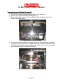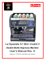
1
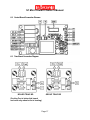
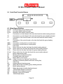
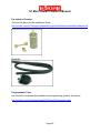
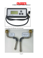
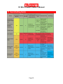
La Spaziale S1 Mini Vivaldi II Double Boiler Espresso Machine User’s Manual Rev. E Updated on 11/15/2012 to clarify Boiler button operation S1 Mini Vivaldi II Owner’s Manual Table of Contents 1 2 3 4 Feature Overview ..................................................................................................... 1 Reference Photos .................................................................................................... 2 Document Scope – Caveats and Clarifications ........................................................ 3 Basic Machine Operation ......................................................................................... 3 4.1 15 Amp or 20 Amp Operation (READ ME FIRST) ............................................ 3 4.2 Initial Installation Before Connecting Power ...................................................... 4 4.3 Filling the Water Tank ....................................................................................... 5 4.4 Turning On and Heating the Machine ............................................................... 6 4.5 Espresso Brewing ............................................................................................. 7 4.6 Volumetric Dose Programming ......................................................................... 7 4.7 Hot Water Delivery ............................................................................................ 8 4.8 Steam Delivery.................................................................................................. 8 4.9 Boiler Operational Modes ................................................................................. 9 4.10 Espresso Group Water Temperature Regulation ......................................... 11 4.10.1 Standard Temperature Adjustment .......................................................... 11 4.10.2 Offset Temperature Adjustment ............................................................... 11 4.10.3 Extreme Temperature Set Function ......................................................... 13 5 Alarm Handling....................................................................................................... 14 5.1 No Water in Tank ............................................................................................ 14 5.2 Coffee Group Water Dosing System Failure ................................................... 14 5.3 Coffee Group Temperature Detection System Failure .................................... 14 5.4 Steam Boiler Temperature Detection System Failure ..................................... 15 5.5 Damaged Group Heating Element Triac ......................................................... 15 5.6 Damaged Boiler Heating Element Triac .......................................................... 15 5.7 Boiler Automatic Refill System Failure ............................................................ 15 6 Connection Diagrams............................................................................................. 16 6.1 Electrical Connection Diagram ........................................................................ 16 6.2 Control Board Connection Diagram ................................................................ 17 6.3 Triac Board Connection Diagram .................................................................... 17 6.4 Control Panel Connection Diagram ................................................................. 18 6.5 Wiring Diagram Definitions.............................................................................. 18 7 Mini VII Water Flow Diagram.................................................................................. 19 8 Adjustments and Maintenance ............................................................................... 19 8.1 Group Pressure Adjustment ............................................................................ 19 8.2 External Mini VII Surface Cleaning ................................................................. 20 8.3 Routine Group Cleaning ................................................................................. 20 9 Optional Accessories ............................................................................................. 21 10 Other LaSpaziale Mini VII Resources .................................................................... 25 11 Quick Setting Guide ............................................................................................... 26 S1 Mini Vivaldi II Owner’s Manual 1 Feature Overview Dual Boiler Steam Boiler 1.2 liter Comes with NEW .9 mm 4-Hole Steam Tip Steam Boiler Element 1250 Watts Group Boiler .45 liter Group Boiler Element 800 Watts Programmable Offset Differential Swivel Stainless Steel Steam Arm Two 53 mm Portafilters: One Single and One Double Manual Fill 3 liter Water Tank Vibratory Pump (Extremely Quiet) Volumetric Dosing Volumetric Dosing Adjustable Through Touch Pad One Degree Group Temperature Adjustability Indicated by LED Display Group Temperature Adjustable Through Touch Pad Electronic Boiler Refill Built-in Safety Thermostat Built-in Safety Cut Out on Vibe Pump Semiautomatic Hot Water Delivery Lever Steam Valve same as La Spaziale S5 Commercial Machines. Fault Diagnosis Alarms Dual Manometer OPTIONAL Pre Infusion Chamber OPTIONAL 7 Day Programmable Timer OPTIONAL No Burn Steam Arm OPTIONAL longer La Spaziale steam arm OPTIONAL Drain Kit Color Black or Red 110 volt Functions in either 15 amp or 20 amp ETL Sanitation Listed (Conforms to ANSI/NSF STD 4) c ETL us Listed (Conforms to UL STD 197 Certified to CAN/CSA STD C22.2 NO. 109 Page 1 S1 Mini Vivaldi II Owner’s Manual 2 Reference Photos These numbered photos will be referenced throughout the document; i.e. (13) Page 2 S1 Mini Vivaldi II Owner’s Manual FIGURE 1 – Indicator Lights and Control Buttons Label Function Label Function Label Function Label Function 1 Drip Tray 9 Control Panel 17 94C Lamp 25 2 Steam Arm 10 18 95C Lamp 26 3 Rubber Feet 11 Group Portafilter Handle Double Cup Button Boiler Button 19 96C Lamp 27 On/Off Button 4 Water Tank 12 Drip Tray Grate 20 97C Lamp 28 5 Side Panels 13 Boiler Lamp 21 6 Steam Lever 14 91C Lamp 22 7 Cup Warming Tray 15 92C Lamp 23 8 Splash Panel 16 93C Lamp 24 Empty Water Tank On/Standby Lamp Hot Water Button Single Cup Button 29 30 Hot Water Outlet Steam Pressure Gauge Group Pressure Gauge 3 Document Scope – Caveats and Clarifications This manual includes material that both duplicates and enhances the official LaSpaziale S1 Mini Vivaldi Instruction Manual in key areas. However, it does not duplicate the detailed and very important information covering machine certifications or ratings nor does it repeat all the warning and safety information contained on the “lawyer” pages. That information, as contained in LaSpaziale Instruction Manual Part # LSC 014-UK Rev.00 or later, is considered included in this document by reference. The official LaSpaziale S1 Mini Manual covers the Mini Vivaldi I and the Mini Vivaldi II plus one option not currently offered or required in the consumer market. That option, as well as material intended specifically for the Mini Vivaldi I, has been omitted from this document. This document solely covers the S1 Mini Vivaldi II plus options available and supported by Chris Coffee Service and/or other vendors supplied by Chris Coffee Service through its exclusive distribution agreements with La Spaziale S.p.A. 4 Basic Machine Operation (BOLD = lamps, Reverse = buttons, numbers in parentheses reference to above table) 4.1 15 Amp or 20 Amp Operation (READ ME FIRST) Please read this section first, especially if you purchased the 20A version of the LaSpaziale VII Mini but do not currently have an available 20A outlet. The LaSpaziale Mini VII can be purchased in 15A and 20A versions. In actuality, they are both identical machines. There is an internal switch that selects the operating mode and they have different power cords installed. The power cord is the easiest way to tell which version you have. The 15A Mini VII has a standard 3-prong AC plug with two parallel blades and a round ground pin. The 20A Mini VII has a 3-prong plug with two Page 3 S1 Mini Vivaldi II Owner’s Manual perpendicular blades and a round ground pin. The 20A version therefore requires a 20A circuit which has a special 20A outlet which accepts the 20A plug. Most modern kitchens have 20A circuits. However, they often do not use 20A outlets because multiple outlets may be on the same 20A circuit. If you have a 20A circuit with a 20A outlet this most likely means that outlet has its own dedicated 20A circuit and is safe to use with the Mini VII. A 20A circuit with normal 15A outlets probably means that multiple kitchen outlets are on the one 20A circuit. Often this means the refrigerator outlet. 20A Mini VII owners should contact their electrician if unsure how to proceed. The internal switch which places the Mini VII in 15A mode does so by never allowing the group boiler and the steam boiler to operate at the same time. When the thermostats for both boilers try to turn on at the same time, the group boiler always has precedence, and then the steam boiler operates in sequential fashion. A number of 15A Mini VII owners note that they see little operational effect when running in this mode. The 20A Mini VII allows both boilers to operate simultaneously. HOWEVER, it is possible to place the 20A Mini VII into 15A mode by removing the top cover from the machine and flipping the internal mode switch. This is often referred to as “Economy Mode”. Economy mode is a great option for those that really want the 20A machine but that do not currently have a 20A circuit. In addition to flipping the mode switch from 20A to 15A operation, this will require swapping out your standard 15A outlet with a 20A outlet. These are readily available from most hardware stores. For a more temporary solution there is an alternative such as this adapter cable available from Chris Coffee Service: http://www.chriscoffee.com/products/home/espressoaccs/20t015adaptorplug. It is also available elsewhere or you can make your own with a quick trip to your local hardware store. 4.2 Initial Installation Before Connecting Power After removing the Mini VII from its packing carton and setting it on the counter, check for additional installation instructions that may be included. You should also have all the accessories shown in the photo below plus a rubber backflush disk (not shown). Page 4 S1 Mini Vivaldi II Owner’s Manual Tip the Mini VII on its side. Twist all four rubber feet (3) hand tight as they may vibrate loose during shipping. While performing that task, use a screwdriver to ensure that the four screws on the bottom (two on each side between the rubber feet) which fasten the two side panels (5) to the chassis bottom are tight. These steps will help ensure the quietest possible operation of your Mini VII. Important Tip: Your Mini VII dealer may request that you check that your water hardness is below a certain level to ensure long life and trouble free operation. Hardness test strips may be included for this purpose. If your water fails this test, contact your Mini VII dealer and discuss the available options. This test should be done before using your machine. Water over 3 grains of hardness needs to be softened or else consider using bottle water. Hard water will require frequent descaling which is not a trivial procedure on this machine. Over time use of very hard water could result in the need to replace the steam boiler heater element. Since the VII Mini has a sealed boiler, replacement of the entire boiler is required. This is not an inexpensive repair. Be forewarned. Use soft water. 4.3 Filling the Water Tank 1) Remove the drip tray (1) 2) Remove the water tank (4) and fill with soft water to ensure against mineral buildup in your boilers 3) Replace the water tank (4) and the drip tray (1) 4) Insert the plug into the 110V AC socket, the On/STBY light (22) starts flashing. (Stand-by mode). 5) Press the ON / OFF (27) and Hot Water (23) buttons simultaneously. During this stage, the control lights EMPTY and On/STBY (22) blink while the pump runs Page 5 S1 Mini Vivaldi II Owner’s Manual 6) Once you see water coming from the group (10), release both buttons. The unit is now in Standby mode with the On/STBY light blinking. You have now primed the pump and filled both boilers with water. Important Tip: The above procedure is only required on the initial use of the machine or any time when starting up with empty boilers such as after storage, boiler clean out, shipment, etc. or any time the boilers have previously been drained. Otherwise, once this procedure is performed once, it is only necessary to turn the machine on using the ON / OFF (27) button. It is NOT required to perform the above procedure each time the water tank is refilled. 4.4 Turning On and Heating the Machine 1) Place the desired coffee basket (Single or Double) into one of the portafilter handles and attach it to the group. 2) Insert the plug into the 110V AC socket, the On/STBY light (22) starts flashing. (Stand-by mode). 3) Press the ON / OFF (27) and button and keep it pressed for about 3 seconds, the green On/STBY light (22) changes from flashing to steady indicating the machine is ON. At the same time the lights from (14) to (21) turn on steadily for about a second (indicating power on test mode). Page 6 S1 Mini Vivaldi II Owner’s Manual 4) The light corresponding to the set temperature starts flashing to indicate that the group is heating and the automatic boiler refill starts until the water level preset by the manufacturer is reached. 5) Once the filling process is finished, the BOILER light (13) starts flashing to indicate that the boiler is heating. However, after first switching on, the boiler doesn't work until the group has reached the set temperature. 6) Fasten the portafilter handle (11) to the brewing group (10). 7) Wait until the set temperature is reached, by checking that the lights on the control panel (9) gradually turn on as the temperature rises. The visualization starts as soon as the temperature reaches 91°C (turning on of light 14) and continues until the machine has reached its operating temperature (light from flashing to fixed). 8) When the group has reached the set temperature, the boiler heating starts (BOILER light (13) flashing), once it reaches the set temperature the light becomes fixed. 9) Every time the group temperature or the boiler temperature drops under the set value, the respective light starts flashing (heating phase) until the set temperature is reached. 10) The machine is now ready. Important Tip: To activate and deactivate the boiler mode press the BOILER (26) button. When the unit it turned off, then back on or even unplugged, then plugged back in, the Mini VII will remember the last state of the Boiler mode. When the boiler is turned off, it is impossible to use hot water for infusions or steam delivery. 4.5 Espresso Brewing 1. Unfasten the portafilter handle (11) from the brewing group (10) and insert the filter for one or Double Cups. Fill it with ground coffee, making sure not to leave coffee powder on the upper edge of the portafilter handle (11), and press it with the suitable coffee tamper provided. 2. Firmly attach the portafilter handle (11) to the brewing group (10). 3. Place one or Double Cups under the portafilter handle (11). 4. Press the button corresponding to Single Cup (24) if you want to make one coffee or Double Cups (25) to start the delivery. Once the desired quantity of coffee programmed is reached, the delivery automatically stops. 4.6 Volumetric Dose Programming The programmable volumetric dosing feature allows programming of the Single Cup (24) and Double Cup (25) buttons to dispense whatever quantities of espresso the user desires. Their use for single cup and double cup quantities is merely a suggestion. Many users only pull double shots and program the double shot button for 1.5-2.0oz for that purpose. Then they program the Single Cup button for a larger Page 7 S1 Mini Vivaldi II Owner’s Manual amount for use in flushing the portafilter basket and/or the group between shots. The beauty of the programmable dosing feature is that the machine owner can be creative. The following are the instructions for programming each button assuming they are being used for single and double shots. 1. With the machine on, press the ON//OFF (27) button and keep it pressed for about 3 seconds; the control light (22) and the one indicating the set temperature start flashing. 2. Insert the single cup basket into the portafilter handle (11) and fill it with 7-8g of ground coffee making sure not to leave coffee powder on the upper edge of the portafilter handle, and press it with the included plastic tamper or, more optimally, a high quality 53mm coffee tamper. 3. Fasten the portafilter handle (11) to the brewing group (10), placing a cup under the portafilter handle. 4. By pressing the Single Cup button (24) the delivery starts and the lights 14-15-16 turn on to show that the one shot espresso dose is being programmed. 5. When the coffee inside the cup has reached the desired quantity, again press the button (24) to stop the delivery. 6. You automatically return to the initial visualization. 7. Repeat the previous steps above using the Double Cup button (25) making sure you change the filter inside the portafilter handle (11) to the double shot basket and fill it with 14-16g of espresso first. 4.7 Hot Water Delivery (only possible with the boiler turned on, BOILER light 13 on) 1. Place the pitcher below the hot water output (28): 2. Press the Hot Water delivery push-button (23). 3. The hot water delivery starts. 4. Once the desired quantity is reached, stop the delivery by pressing the Hot Water button (23) again. Important Tip: The steam/hot water boiler on the V2 Mini is not very large. When using it for hot water, it is suggested that no more than ~6oz be removed at a time and then let the unit refill the boiler before using again. Otherwise, you run the risk of exposing the steam boiler heater element while it is powered up and possibly damaging it. 4.8 Steam Delivery (only possible with the boiler turned on, light 13 turned on) 1. Insert the steam wand (2) in the pitcher containing the drink to be heated. 2. Push the steam lever (6) up, regulating the steam flow according to the need. 3. At the end of the heating phase of the drink, stop the steam delivery by pulling the steam lever (6) all the way down. Page 8 S1 Mini Vivaldi II Owner’s Manual 4. Remove the pitcher from the steam wand (2) and wipe the steam wand and tip immediately with a clean, damp sponge in order to remove all residue of the heated drink. 5. NOTE: The steam lever (6) will remain in the all the way up position when released. However, if released in any other position, the lever will automatically drop to the off position. Important Tip: Do not engage the steam lever (6) before placing the steam wand (2) inside the pitcher, in order to avoid burns. 4.9 Boiler Operational Modes There are three possible operational modes of the two boilers in the LaSpaziale Mini VII 20A model: Both boilers are completely independent, turning on and off according to the needs of each. Both can be on at the same time. This is the default mode with the BOILER enabled and 20A mode selected using the internal 15A/20A switch. The BOILER button can toggle the Boiler on and off. This mode is useful for those that only drink espresso and do not need steam or hot water and want to conserve energy. This can be used to keep the boiler off regardless of whether the machine is running in 15A or 20A mode. Important Tip: The state of the BOILER button is kept in memory and is maintained through On/Stby cycles, when the unit is unplugged, or if there is a power failure. The Mini VII can also be switched into Economy (15A) mode. In this mode, only one boiler can be on at a time. The Mini VII automatically controls which is on according to demand with preference going to the group boiler. This is useful for those owning the 20A model but lacking a 20A circuit. How to do this is described below. Turning the Steam/Hot Water Boiler On and Off 1. The Mini VII must be in ON mode, not Standby for all operations below. 2. With the BOILER lamp on, press and hold the BOILER button until the BOILER lamp turns off. Neither steam nor hot water is available. As noted above, the Mini V2 remembers the current state of the BOILER button through Off/On cycles, when the machine is unplugged, and through power failures. 3. Press the BOILER button again until the BOILER lamp turns back on. 4. When the BOILER lamp is on (or blinking), steam and hot water are available. Page 9 S1 Mini Vivaldi II Owner’s Manual Turning Economy (15A Mode) On and Off 1. The Mini VII must be unplugged and allowed to cool down first. 2. Remove any cups from the cup warming tray (7) 3. Remove the single screw in the front middle of the cup warming tray (7) as shown in the photo below 4. From the front of the machine look down into the top of the machine. In the right rear of the machine you will see a toggle switch with its positions labeled 15 and 20. Reach down with the same screwdriver you used to remove the cup warming tray and flip the switch to the desired position. Page 10 S1 Mini Vivaldi II Owner’s Manual 4.10 Espresso Group Water Temperature Regulation 4.10.1 Standard Temperature Adjustment 1. When the machine is On (ON/STBY solid green), press the button ON/OFF (27) and keep it pressed for 3 seconds, the control light (22) and the one concerning the set temperature start flashing. For example, if the set temperature is 95°C, light (18) starts flashing. 2. In order to change the operating temperature, press and release the Hot Water button (23); every press of the button corresponds an increase of the temperature of 1°C (with the flashing of the corresponding light). When the maximum temperature of 97°C (20) is reached, the selection restarts from the minimum temperature of 91°C (14) (cyclic mode). 3. Once you choose the desired temperature, in order to lock in this value, press the ON/OFF (27) button, the machine will then go back to its normal functioning. The value of the operating temperature of the machine is easily changed in order to improve the final result in the cup depending on the coffee blend used and the user’s personal preference. 4.10.2 Offset Temperature Adjustment What Does Temperature Offset Do? / How Do I Use it? The Vivaldi group design exhibits a temperature drop between where the group boiler temperature probe is located and where the hot water exits the group. Consequently, the temperature setting shown by the temperature lamps on the front panel may differ from the water temperature at the group. Ideally, most users would prefer that the temperature indicated by the temperate lamps exactly matches the water temperature exiting the group. LaSpaziale has partially accounted for this in its basic design. However, there are too many machine to machine electrical and mechanical variances for this to be completely effective. That’s where the temperature offset comes in. The programmable temperature offset allows a user with accurate group temperature measuring equipment to enter an offset in the range of ±8˚C (for extended offset option or 0 to -8˚C for standard offset option) in order to allow their machines temperature lamps to exactly match the water temperature exiting the group. Those purchasing new machines from Chris Coffee Service have had the temperature offset professionally programmed used a Scace device. However, for those obtaining the expanded offset capability via an upgrade, it is recommended that you note the current offset prior to upgrading and then duplicate that offset using the instructions below. If you do not know how to tell what your current offset is, you can find out by entering the temperature offset mode and then following instructions in paragraph 4.10.2. Page 11 S1 Mini Vivaldi II Owner’s Manual 4.10.2.1 Extended Temperature Offset Adjustment Start with the machine in Standby mode (ON/STBY blinking green). Press and hold the BOILER button for about 10 seconds until the Boiler light and the ON/STBY light start flashing. You are now in the temperature offset programming mode. To enter a positive temperature offset between 0˚C and +8˚C push the Single Cup button. Each press will change the offset by +1˚C. An offset of 0˚C is designated by all temperature lamps off. A +8˚C offset is designated by all temperature lamps plus ECON on (Low Water on Mini VII Mini). If your positive offset is more than you wish, each press of the Double Cup button changes the offset by -1˚C. To enter a negative temperature offset between 0˚C and -8˚C mode push the Double Cup button. Each press will change the offset by -1˚C. An offset of 0˚C is designated by all temperature lamps off. A -8˚C offset is designated by all temperature lamps plus EMPTY on. If your negative offset is more than you wish, each press of the Single Cup button changes the offset by +1˚C. How Do I Tell If My Current Offset is Negative or Positive? Example: You enter Offset Programming mode and see that three lamps are on. This can indicate either ±3˚C. Which is it? Since each press of the Double Cup button changes the offset by -1˚C, press it and see what happens. There will either be two or four lamps lit. If four lamps are lit the offset must have been -3˚C since pressing Double Cup always changes the setting by -1˚C with each press. If two lamps are lit the offset was +3˚C. By pressing Double Cup the offset has changed to +2˚C. -8 -7 -6 -5 -4 -3 -2 -1 0 +1 +2 +3 +4 +5 +6 +7 +8 ˚C Offset ---------------------------------------------------------- Single Cup Button --------------------------------------------------------- Double Cup Button Note that neither the Single Cup nor the Double Cup button presses wrap around when they reach the limit of their range. Once you get to +8˚C additional presses of the Single Cup button do nothing. Same with the Double Cup button once -8˚C is reached. Page 12 S1 Mini Vivaldi II Owner’s Manual See table below: Offset 0ºC ±1ºC ±2ºC ±3ºC ±4ºC ±5ºC ±6ºC ±7ºC ±8ºC 91ºC Lamp Off On On On On On On On On 92ºC Lamp Off Off On On On On On On On 93ºC Lamp Off Off Off On On On On On On 94ºC Lamp Off Off Off Off On On On On On 95ºC Lamp Off Off Off Off Off On On On On 96ºC Lamp Off Off Off Off Off Off On On On 97ºC Lamp Off Off Off Off Off Off Off On On EMPTY Lamp Off Off Off Off Off Off Off Off On 4.10.3 Extreme Temperature Set Function Standard temperature programming described in section 4.10.1 allows a range from 91ºC to 97ºC in 1ºC increments. There may be times when the user desires a temperature outside of this range. While the Offset mode described in section 4.10.2 could be used for this purpose, it is best to use the offset as intended. Once set properly, the offset should be left alone. Instead, the VII Mini includes a mode specifically for use in extending the temperature range above 97ºC or below 91ºC up to a max of 3ºC. While the ability to extend the temperature above 97ºC is of limited use, there are some types of coffee whose flavor is optimum in the 88ºC to 90ºC range. Note that the method below only works if the master temperature is set to either 91ºC or 97ºC. If the temperature is set to 91ºC you can only use the instructions below to lower the temperature by 1ºC, 2ºC, or 3ºC. If the temperature is set to 97ºC you can only use the instructions below to raise the temperature by 1ºC, 2ºC, or 3ºC. Consequently you must use the instructions provided in section 4.10.1 to set the master temperature to 91ºC or 97ºC BEFORE using the instructions below. If this is not done, the instructions below for entering the Extreme Temperature Set mode will work as described, but once in that mode attempting to a raise or lower the temperature has no effect. Instructions for programming this mode AFTER setting the master temperature to 91ºC or 97ºC are: Start with the machine in Standby mode (ON/STBY light flashing). Press and hold the Two Cup button for ~3 seconds until lights 94ºC (17) and 95ºC(18) come on indicating that the Extreme Temperature Function setting mode is active. Page 13 S1 Mini Vivaldi II Owner’s Manual If you start with the master temperature set to 97ºC, each time that the Hot Water button is pressed, lights 96ºC (19), 97ºC (20), and Tank Low (21) will switch on in succession. Each light indicates a 1ºC increase. All three lights on = 100ºC. If you start with the master temperature set to 91ºC, each time that the One Cup button is pressed, lights 93ºC (16), 92ºC (15), and 91ºC (14) will switch on in succession. Each light indicates a 1ºC decrease. All three lights on = 88ºC. Press the Two Cup button again to exit Extreme Temperature set mode and return back to Standby mode Note: When you change the temperature of the 91ºC and/or 97ºC buttons according to the above instructions, the change only remains in effect until the temperature is changed. For example, if you change the 91ºC selection by 3ºC to yield 88 ºC, then later change the temperature to 93C, the next time you select 91ºC, you will get 91ºC, not 88 ºC. If you wish to obtain 88ºC again you will need to follow the above instructions to reprogram in the 3 ºC decrease. 5 Alarm Handling The Mini VII uses computerized sensors to robustly handle Mini VII device malfunctions. There are two types of alarms the Mini VII can generate: Blocking Alarms – these are the most serious. The VII will turn itself Off and display the alarm codes noted below when one of these alarms occurs. Non-Blocking Alarms – These are informational only and, while they do represent an error condition, the machine will continue to function. 5.1 No Water in Tank When the tank (4) is out of water the red EMPTY light (21) comes on and remains on until at least 1liter of water is added. The tank can hold up to 3 liters. 5.2 Coffee Group Water Dosing System Failure When the flow meter isn't working properly or when the coffee grind is too fine, this is indicated by the turning on of the lights 14-15-16; if you are making one coffee dose, and the lights 17-18-19 if you are making two coffee doses. This is a non-blocking alarm. This alarm is actually useful when back flushing as an indication of when to turn off the pump and allow the 3-way valve to operate. 5.3 Coffee Group Temperature Detection System Failure This alarm is a blocking one, and occurs when the temperature probe of the group is in short circuit (temperature >145°C) or is in open circuit (disconnected) condition (temperature <60°C). The lights 20-21 turn on. Page 14 S1 Mini Vivaldi II Owner’s Manual If the group water temperature does not exceed 60°C within 5 minutes of turning the unit on, this alarm will also occur. Turn off the Mini V2 and request service. 5.4 Steam Boiler Temperature Detection System Failure (only with the boiler turned on) This is a blocking alarm and occurs when the temperature probe of the boiler is in short circuit (temperature >145°C) or it is in open circuit (disconnected) condition (temperature <60°C). The lights 19-20-21 turn on. The alarm can be temporarily cleared by turning the boiler off (Press BOILER (26) button.) Eventually you will need to turn off the Mini V2 and request service. 5.5 Damaged Group Heating Element Triac This alarm is a blocking one, and occurs when the group triac always remains in conduction (temperature >140°C). The lights 20-21 are flashing. Turn off the Mini V2 and request service. 5.6 Damaged Boiler Heating Element Triac (only with the boiler turned on) This alarm is a blocking one, and occurs when the boiler triac always remains in conduction (temperature >140°C). The lights 19-20-21 are flashing. Turn off the Mini V2 and request service. 5.7 Boiler Automatic Refill System Failure (only with the boiler turned on) This is a blocking alarm which is signaled by blinking of the Boiler (13) light. If the pump runs for more than 1 minute attempted to refill the boiler without the controller circuit receiving a boiler full signal, this alarm is triggered. This alarm can be temporarily cancelled by pressing the BOILER (26) button to turn off the boiler. The Mini VII can be operated with the steam boiler off until repairs to the boiler function occur. Factoid: A triac is a device to which a small DC control voltage can be applied in order to turn on a large AC current source. One is used for each boiler in the VII. Think of a triac as a solid state semiconductor equivalent of an electromechanical relay. TRIAC is an acronym for Triode for Alternating Current. Page 15 S1 Mini Vivaldi II Owner’s Manual 6 Connection Diagrams 6.1 Electrical Connection Diagram Page 16 S1 Mini Vivaldi II Owner’s Manual 6.2 Control Board Connection Diagram 6.3 Triac Board Connection Diagram BOILER TRIAC BD GROUP TRIAC BD (Cooling Fan is below this board and runs only when boiler is heating) Page 17 S1 Mini Vivaldi II Owner’s Manual 6.4 Control Panel Connection Diagram 6.5 Wiring Diagram Definitions EV GR Coffee brewing group solenoid valve EV H Hot water delivery solenoid valve EV AL Automatic refill system solenoid valve T1 Connection on control board of the triac that feeds the boiler heating element T2 Connection on control board of the triac that feeds the group heating element P1 Connection of the control board on the triac that feeds the boiler heating element P2 Connection of the control board on the triac that feeds the group heating element SER 1 Connection control panel on control board SER 2 Connection control board on control panel F Flow meter F1 in Phase inlet into the triac that feeds the boiler heating element F1 out Phase outlet from the triac that feeds the boiler heating element F2 in Phase inlet into the triac that feeds the group heating element F2 out Phase outlet from the triac that feeds the group heating element S1 Boiler temperature probe S2 Brewing group temperature probe SL Container water level sensor SB Boiler Water Level Control Display Cable Connector for Optional Timer Module V Ventilator connection (steam boiler triac cooling fan) P Vibe Pump RC Heating element brewing group TSC Safety thermostat for brewing group heating element RB Boiler heating element TSB Safety thermostat for boiler heating element JP4 15/20A Mode Selector Connection JP3 Optional Timer Switch Connector SD Optional Timer On/Off Switch SE 15/20A Mode Switch Page 18 S1 Mini Vivaldi II Owner’s Manual 7 Mini VII Water Flow Diagram The information below is provided strictly as a reference for Mini VII owners who are curious about the function of their Mini VII Dual Boiler design. 8 Adjustments and Maintenance 8.1 Group Pressure Adjustment Conventional espresso guidelines call for group pressure in the range of 8.25-9.5 Bars. This is normally set to 9.0 bar prior to shipment. Should you wish to try a lower pressure or, if adjustments are required at some future time, use the procedure documented below. 1) Pull out the drip tray and set it aside 2) Remove the two screws holding the chrome front splash panel in place. (The panel that the pressure gauge protrudes through.) 3) With the panel removed you will see the adjustment nut shown in the photo below. 4) Insert the portafilter with the rubber disk inserted or using a “blind basket”, the same as you would do for backflushing. 5) Press the One Cup or Two Cup Button. 6) Use either the correct metric box wrench or an adjustable wrench to adjust the group pressure as noted on the group pressure gauge to your desired value. Turn right to increase pressure, left to decrease pressure. Page 19 S1 Mini Vivaldi II Owner’s Manual 8.2 External Mini VII Surface Cleaning Use a damp sponge and wipe dry with a soft cloth. Alternately, window cleaner wiped off with a dry soft cloth works well. 8.3 Routine Group Cleaning The Official LaSpaziale Method” The extra pair of shower screens was not included with your Mini VII so you'd have an extra set. They are included as part of LaSpaziale’s recommended cleaning regimen which is targeted at light commercial use where there is no time for a complete detergent based back flush routine. The reason for LaSpaziale’s double shower screen arrangement is to trap grounds between the screens so that the 3-way valve rarely, if ever, needs a detergent cleaning. With the Mini VII on and fully heated, use the included key wrench to remove the shower screen bolt. Drop out the two screens and the dispersion disk. Page 20 S1 Mini Vivaldi II Owner’s Manual Use the included plastic handled wire brush to quickly scrub the group head while water is running through the group to flush out the particles. (This is why the long handled brush - to keep your hands away from hot water.) Also, give the dispersion disk a quick scrub. Reassemble using the other set of screens. Soak the original set of screens in Cafiza, Joe Glo, or similar detergent, scrub, rinse, and put away for next time. The Way Most Mini V2 Users Actually Do It: As noted above the official LaSpaziale method was developed assuming the machine is in light commercial use. This is certainly not the target market for the Mini V2. Here is how most users clean their coffee group (once every 3-4 weeks is enough): Start with the basic procedure above, though most folks use something like a Pallo brush rather than the wire brush that came with the machine for the 3 rd step. Once the clean screens and dispersion disk are back in the machine perform the following steps. Using 1/3 tsp Cafiza, Joe Glo, or similar detergent every 2-4 weeks is plenty for home use. Backflush the S1 Vivaldi II Mini more often with plain water. Place the backflush disk in the double basket with 1/3 tsp of Cafiza powder. Press the single cup button. Wait 5-10 seconds. Press the single cup button again to stop the pump which automatically engages the 3-way valve. Perform the above cycle 5 times waiting about 30 seconds between each cycle. Then rinse the remaining detergent from the basket and replace the portafilter with the backflush disk still installed. Backflush for 5 more cycles to rinse the remaining residue from the group and 3-way valve. Remove the backflush disk, make shot of espresso and throw it out. Important Tip: To maximize the effectiveness of the cleaning process and minimize how often a detergent cleaning is required, after every series of shots is pulled, run a shot with the PF remove. Scrub the screens and around the gasket with a Pallo brush while the hot water is exiting the group. This will flush most of the grounds and sediment into the drip tray. 9 Optional Accessories These can be ordered and installation arranged at the time you order the Mini V2. In addition, they can be ordered latter and self-installed if you are the handy with simple metric tools. Page 21 S1 Mini Vivaldi II Owner’s Manual Pre-Infusion Chamber Click the link below for the Installation Guide: http://s1cafe.com/s1v2/images/LaSpazialeProgressionPreinfusionInstallationManual.pdf Drain Kit Programmable Timer Use this link to download the installation and programming guide for this device: http://s1cafe.com/s1v2/images/Vivaldi%20Timer%20Instructions.pdf Page 22 S1 Mini Vivaldi II Owner’s Manual Longer Steam Arm (Shown next to stock arm) Page 23 S1 Mini Vivaldi II Owner’s Manual Optional “No Burn” Steam Arm (shown next to stock steam arm) Optional 4 Hole Tip for “No Burn” Steam Arm This tip is available on the Chris Coffee website: http://www.chriscoffee.com Pictured below side-by-side are the stock 2 hole tip and the new 4 hole tip. Page 24 S1 Mini Vivaldi II Owner’s Manual 53mm Triple Basket By popular demand Chris Coffee now sources a triple basket for the S1. This basket can be purchased by itself or it is included with purchase of a bottomless portafilter. 10 Other LaSpaziale Mini VII Resources In addition to your Mini VII supplier, current users are an excellent information resource: Check out these internet sites: http://www.home-barista.com – reviews, forums, and lively discussions on all coffee topics http://www.coffeegeek.com - Here you will find lively debate on all things coffee and Mini VII information, including reviews by owners. http://www.s1cafe.com/s1v2 – Website devoted solely to the LaSpaziale VII and Mini VII with links to one dedicated to the VI and to the forum below http://www.s1cafe.com - an on-line forum for VI, Mini VII, and Mini VII Mini owners to share information and ask questions. http://www.bellabarista.co.uk/pdf/Laspaziales1MiniVivaldicloserlookv2.pdf - This is actually a detailed review of the VI Mini widely sold outside the United States. However, most of this information is equally applicable to the VII Mini. Page 25 S1 Mini Vivaldi II Owner’s Manual 11 Quick Setting Guide Page 26