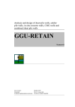
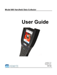
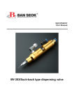
1
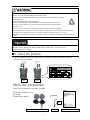
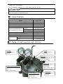
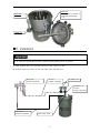
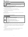
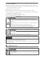
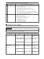
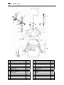
INSTRUCTION MANUAL
■PRESSURE TANK
PET-10
This manual contains IMPORTANT WARNINGS and
INSTRUCTIONS.
Equipment in this manual is exclusively for
painting purposes.
Do not use for other purposes.
The operator shall be fully conversant with the
requirements stated in this instruction manual
including important warnings, cautions and
operation and correct handling.
Read and understand the instruction manual,
before use and retain for reference.
This Anest-iwata pressure tank complies to ATEX
regulations 94/9/EC,
Protection level :
Ⅱ2 G T6 X,Suitable for use in Zones 1 and 2.
X marking :
Any static electricity discharge from the pressure
tank is to be diverted to the grounded by connecting
stipulated.
■Contents
Important information
1. Safety precautions・・・・・・・・・・・・・・・・・・・・・・・・・・・・2
2. Check the products・・・・・・・・・・・・・・・・・・3
3. Specifications・・・・・・・・・・・・・・・・・・・・・・・・・・・・・4
4. Name of each section an d function・・4
5. Installation・・・・・・・・・・・・・・・・・・・・・・・・・・・・・・・・・5
6. Operation・・・・・・・・・・・・・・・・・・・・・・・・・・・・・・・・・・・6
7. Maintenance・・・・・・・・・・・・・・・・・・・・・・・・・・・・・・・7
8. Problems and remedies・・・・・・・・・・・・8
9. Parts list・・・・・・・・・・・・・・・・・・・・・・・・・・・・・・・・・・・・9
-1-
■1.Safety precautions
Wear protective gear.
During painting, be sure to wear protective gear such as glasses, mask or gloves.
Paints or solvents might enter your eyes or you might inhale them.
If you feel any abnormality during operation, immediately see a medical doctor.
Be careful about ventilation.
・
Use it in a well-ventilated place.
Painting or cleaning in a narrow place with insufficient ventilation can cause organic
solvent poisoning by sprayed mist of paint or volatile solvent.
If you feel any abnormality during operation, immediately see a medical doctor.
・
Sprayed mist of paints or solvents can catch fire, causing fire or explosion, which is
very dangerous.
Danger caused by wrong operation of equipment
・
Never use in another way than to apply pressure for paint transfer.
If done, it can cause insufficient performance or failure.
・
Do not use with corrosive liquids (
halogenated hydrogen carbon, oxygen, alkaline)
.
If done, corrosion can cause failure.
If you consider use of a special cleaning solvent, we are ready to supply you with
a material list of our pressure tank on request.
・
Never point paint (gun) toward a person or animal, or put your finger in front of tip of air cap.
If done, paint can enter human body directly through eyes, mouth or skin. It is very
dangerous.
Keep away from origins of explosion or fires.
・
Never use near sparks or open fire. Especially the following will cause fire. It is
very dangerous.
・
Open flames such as cigarettes or pipes
・
Electric goods such as stoves, lamps or heaters
Contact grounding.
・
Securely ground pump, spray gun, workpieces and containers containing paints or solvent.
Be sure to use Anest Iwata’
s designated urethane air hose (EAHU type) with
built-in ground wire to have continuous grounding between pump and spray gun or
connect grounding separately. Insufficient grounding will cause explosions or fire if exposed to
a spark of static electricity.
Insufficient grounding will cause explosions or fire if exposed to a spark of static electricity.
Be careful about explosion of fluid hose.
・
Never bend hose with a radius of less than 50mm. Never put heavy things on it.
If done, hose can explode, causing great danger.
・
Securely connect hose to avoid leak and looseness.
If hose is disconnected during operation, hazardous hose movement and paint ejection will
cause severe bodily injury.
・
Never use the following hoses. Such a hose can cause great danger during operation.
It is very dangerous.
・
cracked
・
damaged
・
bent
・
crushed or distorted
-2-
Be careful about explosion.
・
Be sure to use it at less than maximum fluid operating pressure.
If done, it can cause damage to the pressure tank or emission of paint or flying parts, resulting in
serious bodily injury.
・
Never remove safety valve or alter setting figures.
If done, it makes it difficult to deal with emergencies, resulting in explosions or accidents.
・
Be sure to release pressure in pressure tank before inspecting or cleaning inside of
pressure tank.
If not done, it can cause serious bodily injury through eruption of paint or flying parts.
Before maintenance or inspection, be sure to release compressed air in pressure tank and make sure by
checking pressure gauge that there is no pressure remaining in the pressure tank. If you do
Maintenance or inspection while pressure remains in tank, parts being disassembled can fly out and caus
injury.
・
Never alter the pressure tank.
・
Be sure to use our genuine parts when you make repairs or replace parts. If not, it can cause
insufficient performance or failure.
■2. Check the products
・Check to make sure that the products are as ordered and that the products have not
been distorted or damaged.
Front
Back
Check the accessories.
Check that accessories have been included.
◎ Pressure regulator ass’
y
◎ Handle
◎ Instruction manual
Nut
Pressure regulator ass’y
-3-
Handle
Instruction manual
How to connect
Secure pressure regulator ass’
y and handle with nut on tank.
Firmly fix handle or pressure regulator ass’
y to tank.
If not, drop of tank can cause bodily injury.
■3. Specifications
Model
PET-10
Capacity
Inner tank capacity (SUS304)
Max. working pressure
Ambient temperature
For tank
Pressure regulator ass’
y
For spray gun
Max. operating air pressure
Air inlet/Air outlet
Fluid tube (SUS303)
Fluid outlet (SUS303)
Fluid passage
Dimensions,
LxWxH
mass
Mass
10L
8.5L
4.0 bar/ 57psi
5∼40℃
4.0 bar/ 57psi
7.0bar/100psi
G1/4
1/2”
G3/8
Stainless Steel
310x310x565 mm
11.6 kg
■4. Name of each section and function
Pressure tank feeds paint in pressure tank by pressure which is adjusted by a pressure regulator.
Air outlet
G1/4 connection to
air hose.
Air inlet
G1/4 connection to
air hose.
Safety valve
Releases air when air pressure
inside pressure tank.
Max: 4.0bar / 57psi
Exhaust valve
Exhausts air pressure in
pressure tank.
Rotate exhaust valve in
anticlockwise direction.
Pressure regulator (spray gun)
Supplies regulated air to spray
gun.
Max: 7.0bar/100psi
Pressure regulator (tank)
Supplies regulated air to
pressure tank.
Max: 4.0bar/57psi
-4-
Paint outlet
G3/8 connection to
fluid hose.
Fluid tube
Feeds paint to outside of
paint tank through tube.
1/2”
Inner tank
8.5L
Thumb nut
■5. Installation
・
It can cause an unpredictable accident if pressure tank suddenly moves or topples.
① Install pressure tank on a horizontal surface so that it does not move.
② Securely connect air hoses to inlet and outlet sides and fluid hose.
Spray gun
prepare separately
Air hose
prepare separately
Air outlet G1/4
Air inlet G1/4
Air hose
prepare separately
Fluid hose
prepare separately
Paint outlet G3/8
-5-
■6. Operation
6−1.Preparation
Be sure to release compressed air before you lift lid and inspect the inside.
If not done, flying parts can cause serious injury.
① Open exhaust valve and release compressed air.
If you loosen thumb nut while compressed air remains in pressure tank, flying parts or paint can
cause serious injury or accidents.
② Loosen thumb nut, lift lid and inspect the inside of pressure tank.
If the inside has become dirty, clean it and pour paint which is filtered.
③ Close lid and securely tighten thumb nut.
Tighten it evenly.
④ Securely connect air hose to air hose connection, and fluid hose to fluid hose connection.
⑤ Close exhaust valve.
6−2.Start-up operation and adjustment
ɾNever remove safety valve or alter setting figures.
If done, safety valve cannot deal with emergencies, resulting in an explosion
or accident.
If shaft of safety valve becomes dirty clean it.
Dirty shaft can cause failure, explosion or accident.
If it is damaged or bent, you must ask a specialist to repair it.
Safety valve has been adjusted to operate as follows:
4bar{
57psi}
ɾ
① Supply compressed air.
Gradually tighten pressure regulator handle to get necessary pressure. If pressure becomes too
high, loosen pressure regulator handle. Air release valve fitted to pressure regulator automatically
releases air pressure in accordance with loosened value. Readjust and fix it after pressure
becomes stable.
② Test spray
During spray test, fully adjust both fluid pressuring air pressure and atomizing air pressure.
Relationship between fluid pressurizing pressure and atomizing air pressure
③ After spray test, start normal coating job.
-6-
6−3.End of operation
① Stop supply compressed air, open exhaust valve to release compressed air pressure in pressure tank.
② Fully return pressure regulator handle (Air release device fitted to pressure regulator releases air from l
ower section of handle but this is not a failure)
③ Remove lid and take out paint in container.
④ Securely tighten lid, feed compressed air into pressure tank and exhaust paint in fluid hose.
⑤ After exhausting paint, stop supply compressed air at air inlet again and turn it to the left till handle
movement of pressure regulator becomes light.
⑥ Clean inside of pressure tank which is in contact with paint.
6−4. Precautions during operation
・As safety valve has been adjusted during assembly at plant, do not readjust it.
If done, it can cause pressure to become higher than necessary and become
dangerous.
・Dirty safety valve fails and can also be dangerous. Pay special attention to this
point.
Safety valves for have been adjusted to operate at 4bar{
57psi}
.
・Be sure to release air pressure in pressure tank before replenishing paint.
If not done, parts can fly and paints scatter, which is very dangerous.
・Be sure to filter air through air filter and supply clean air without moisture and oil to
pressure tank.
If not done, air including moisture and oil can fail paint finish.
・Do not fill pressure tank to more than 80% of its capacity.
If done, paint sticks to lid during transportation, damages rubber valve of pressure regulator or
reverses flow of paint.
■7. Mai
nt
enance
・When disassembling, be sure to turn handle of pressure regulator counterclockwise, and
slacken it completely.
If not done, pressure can cause parts to fly and paint to scatter, causing serious bodily
injury.
-7-
・
Refer to the following table and do the inspection and maintenance.
No.
1
Period
Daily inspection
Contents of inspection and maintenance
① Check cleanliness of safety valve.
・ Clean if appearance is dirty.
・ If safety valve fails, ask a specialist to repair it.
② Check motion of pressure gauge pointer and any damage to
glass. Replace if necessary.
・ Check if pointer returns to 0 position when pressure is not put.
・ Check if pointer moves up gradually when you put pressure gradually.
・ Check to make sure that glass is not broken.
2
Periodic inspection
① Clean pressure tank fully after use. Clean especially suction tubes
and fluid hoses with solvent.
② Visually check inside and outside of the unit.
・ any deformation and crack of tank
・ any deformation of tank lid
・ tightening thumb nut and bolt
・ air leak from tank lid packing
■8.Problems and remedies
Ask the distributor or the shop who sold it to you about ☆ marked items.
If they are not done properly, it can cause poor performance.
Problems
Causes
Research
Remedies
①Pressure does not increase ① Forget supply compres ①Open exhaust valve and
①Supply compressed
(
in tank)
.
sed air.
check exhaust of air.
air fully.
②Exhaust valve and thumb ②Air exhausting sound is
nut are not tightened.
heard (not heard whe ②Close fully.
n normal)
③Pressure gauge is dama ③Air exhausting sound is ③Replace with new
ged.
heard
one ☆
②Paint does not
①Compressed air is not ①Open exhaust valve and ① ・Supply compressed
air fully.
check exhaust of air.
supplied.
・ Tighten pressure
regulator.
come out.
②Forget supply compress ②-dittoed air.
②-ditto-
③Remove lid and inspect
③Replenish paint.
inside.
③Paint runs out.
-8-
■9. Parts list
Pressure tank PET-10
№
1
2
3
4
6
7
10
22
24
25
29
Description
Main body
Lid assembly
Gasket
Handle
Release valve
Adapter (G1/4)
Pressure regulator
Safety valve
Fluid outlet (SUS)
Pressure gauge
Screw bolt
30
Washer
Q’ty
1
1
1
1
1
2
1
1
1
2
4
№
31
32
33
34
39
45
46
47
48
49
50
Description
Thumb nut
C-snap ring
Cotter pin
Fluid tube
(SUS 1/2”)
Air flow guider
Adapter
Adapter
Adapter
Pressure regulator
Fluid outlet adapter(SUS G3/8)
Nut
4
51
Inner tank
-9-
(SUS)
Q’ty
4
8
4
1
1
1
1
1
1
1
1
1
˙ Important information-Safety precautions
・This product is exclusively used for coating. Do not use for other purposes than coating.
・Be sure to read and understand this instruction manual for correct operation. The operator shall be
fully conversant with the requirements stated within this instruction manual including important
warnings, cautions and operations.
・Wrong operation (mishandling) can cause serious bodily injury, death, fire or explosions.
˔Safety factor
・ Safety precautions in this instruction manual are minimum requirements. Observe other regulations about
electricity, safety and fire fighting designated by your country, local government and company.
・ Pay special attention to items which are shown by the below marks and symbols.
・ Marks and symbols mean as follows:
・
Marks of warnings and cautions
Indicates a potentially hazardous situation which, if not avoided,
could result in death or serious injury.
Indicates a potentially hazardous situation which, if not avoided,
may result in minor or moderate injury or property damage.
Examples of symbols
Indicates [you must be careful]. We will explain briefly in or near the symbol.
(The example on the left is [be careful about ventilation].)
Indicates [you must not do]. We will explain briefly in or near the symbol.
(The example on the left is [Do not touch].)
Indicates [you must do]. We will explain briefly in or near the symbol.
(The example on the left is [be sure to wear protective mask].)
※We shall not be responsible for any injury or damage caused by disregard of warnings, cautions or instructions.
˔ Supplementary notes
Important
Indicates notes which we ask you to observe. They are helpful to achieve
full performance and function of the equipment.
3176,Shinyoshida-cho, Kohoku-ku,
Yokohama 223-8501, Japan
Manual No.T410-00
Code No.04016010