1
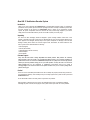
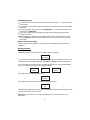
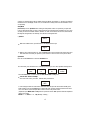
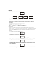
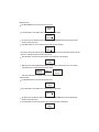
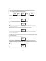
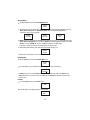
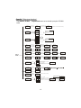
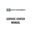
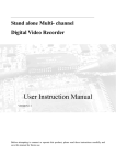
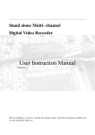
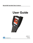
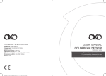
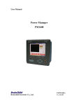
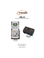
AR-12
Archi Recorder
Preset 1
Preset 4
Preset 2
Preset 5
Preset 3
Preset 6
Page 1
Page 2
OFF
AR-12
Archi Recorder
Master Dimmer
NEXT
UP
NO
YES
AR-12P
DOWN
ARCHI RECORDER
(Junction Box )
AR-12
ARCHI RECORDER
(Controller/Keypad)
Web site: www.prolight.co.uk
E-mail: [email protected]
24-004-2171-00Rev1.0
Draft Date:18-May-2007
Table of Contents
AR-12
Page1~Page12
AR-12P
Page13~Page14
About AR-12 Architecture Recorder System
Introduction:
Thank you for your purchasing the Transcension AR 12-Architectural Recorder System. To optimize the
performance of this product, please read these operating instructions carefully to familiarize yourself with
the basic operation of this system. The Transcension AR-12 is simple to use, architecture recorder
system. All system components have been tested at the factory before being shipped to you. Please
simply connect the LAN-cable between your AR-12 and AR-12P, then you're ready to go!
Unpacking:
The AR-12 has been thoroughly tested and shipped in perfect working condition. Please take a few
minutes to carefully inspect the system carton for damage that may have occurred during shipping. If the
carton appears to be damaged, carefully inspect each system component for damage, in the case that
damage is found, please contact our customer support center, listed below, for further instructions. The
AR-12 system carton should includes the following:
1 AR-12C(Keypad)
1 AR-12P(Junction Box)
1 LAN-cable(meet to RJ-45 connector)
1 External Adaptor
1 User's Manual
Customer Support:
Every effort has been made to design dependable and reliable products. New products are constantly
being designed to meet the needs of the entertainment lighting industr y. Your comments regarding our
products and services are welcome. Transcension will provide set up help and to answer any question
should you encounter problems during you set up or initial operation. You may also visit us on the web at
www.prolight.co.uk for any comments or suggestions. And please send us an e-mail to
[email protected] and let us know how to improve to better serve you. It is both a privilege and a
pleasure serving you.
Caution!
There are no user serviceable parts inside this unit. Do not attempt any repairs yourself, doing so will void
your manufactures warranty. In the unlikely event your unit may require service, please contact your nearest
Transcension dealer.
Do not discard this carton in the trash, please recycle when ever possible.
Upon unpacking, carefully inspect your unit for any damage that any have occurred during shipping.
If damage may have occurred, do not plug the unit in, please contact your dealer as soon as possible.
-1-
DMX Set-Up
Data Cable (DMX Cable) Requirements:
The AR-12 can be controlled via DMX-512 protocol and your DMX controller requires a standard 3-pin
XLR connector for data input and data output(Figure1). Connect the AR-12P and your fixtures together
using standard 3 pin DMX cables. The AR-12 uses DMX-512 protocol to operate your fixtures.
If you are constructing your own data cables, be sure to use standard
two conductor shielded cable (This cable may be purchased at almost
all professional sound and lighting stores). Your cables should be made Figure 1
with a 3-pin male and female XLR connector on either end of the cable.
Also remember that DMX lines must be daisy chained and can't be split.
*Note: Be sure to follow figures two and three when making your own cables. Do not use the ground lug
on the XLR connector. Do not connect the cable's shield conductor to the ground lug or allow the shield
conductor to come in contact with the XLR's outer casing. Grounding the shield could cause a short
circuit and erratic behavior.
COMMON
DMX+
DMX 512 OUT
3-PIN XLR
DMX 512 IN
3-PIN XLR
Figure 2
DMX-
XLR Male Socket
1 Ground
XLR Pin Configuration
XLR Female Socket
2 Cold
2 Cold
1 Ground
Pin 1 = Ground
Figure 3
Pin 2 = Data Compliment (negative)
3 Hot
3 Hot
Pin 3 = Data True (positive)
*Special Note:
Line Termination. When longer runs of cable are used, you may need to use a terminator on the last unit
to avoid erratic behavior. A terminator is a 120 ohm 1/4 watt resistor which is connected between pins 2
and 3 of a male XLR connector (DATA + and DATA -). This unit is inserted in the female XLR connector of
the last unit in your daisy chain to terminate the line. Using a cable terminator will decrease the
possibilities of erratic behavior.
1
3
2
Termination reduces signal errors and avoids signal
transmission problems and interference. It is always
advisable to connect a DMX terminal, (Resistance 120
Figure 4
DMX Signal Cable. 120 ohm impedance DMX signal cable MUST be used for signal connection.
5-Pin XLR DMX Connectors.
Some manufactures use 5-pin XLR connectors for DATA transmission in place of 3-pin. 5-pin XLR fixtures
may be implemented in a 3-pin XLR DMX line. When inserting standard 5-pin XLR connectors in to a 3-pin
line a cable adaptor must be used, these adaptors are readily available at most electric stores. The chart
below details a proper cable conversion.
3-Pin XLR to 5-Pin XLR Conversion
Conductor
Ground/Shield
Data Compliment(-signal)
Data True(+signal)
3-Pin XLR Female(Out)
5-pin XLR Male(In)
Pin 1
Pin 1
Pin 2
Pin 2
Pin 3
Pin 3
Not Used
Pin 4 - Do Not Used
Not Used
Pin 5 - Do Not Used
-2-
About AR-12
Product Introduction
AR-12 is a wall-fixed DMX controller with many useful functions. The AR-12 product is used in
combination with an AR-12P unit, and it's specially designed for the supermarket or hall lighting control.
The unit can send standard 512-channel DMX signals, and up to 8 sets of AR-12 units can be linked up for
use. 12 editable programs, 99 recordable Scenes and 12 recordable Shows are provided. Time Call (Time
on and Time off ), calendar and time setting functions are also provided by this unit.
Controls & Functions
1
2
Preset 1
Preset 4
Preset 2
Preset 5
Preset 3
Preset 6
Page 1
Page 2
3
2
3
OFF
4
AR-12
Archi Recorder
Master Dimmer
NEXT
9
UP
NO
10
YES
DOWN
5
6
7
8
1.LCD-display:
Reads current function mode or activity.
2.Preset buttons:
To input the password or used as relevant assigned
buttons.
3.Page buttons 1-2:
Page1: 1-6 Preset buttons available.
Page2: 7-12 Preset buttons available.
4.OFF button:
Press this button, the current DMX value will run to 0
level within the Delay time.
5.Master Dimmer Up button:
Used to adjust relevant Master level. Each tap will
increase the level once.
11
6.Master Dimmer Down button:
Used to adjust relevant Master level. Each tap will decrease the level once.
7.UP button:
To select relative function mode or to increase relevant value.
8.YES button:
To confirm or enter relative operation.
9.NEXT button:
Press this button to step to another item.
10.NO button:
To cancel or return to the previous menu.
11.DOWN button:
To select relative function mode or to decrease relevant value.
-3-
Installation:
User can do the installation and link up relevant units as the following flowchart shows:
unit 1
unit 2
(AR-12)
(AR-12)
unit 8
(AR-12)
(AR-12P)
Power Input
RJ45
AC/DC
12-15V/1.5A
DMX IN
DMX
Controller
IN
IN
OUT
OUT
unit 3...7
IN
DMX OUT
OUT
DMX Pack
(Make sure the cable is suitable and undamaged. User can use the standard CAT-5 cable, and plug it into the
RJ45 connector for better connection effect.)
Notice Information:
(1)Switching on Main Power:
After having finished the installation, make sure each unit is linked up well. turn on the main power, and then
all the LCDs of each AR-12 unit will display the calendar and time.
(2)Address Setting:
The original address of each AR-12 unit is "0".
Preset the address for each unit from 1 to 8, and ensure the addresses are not dittoed.
After finishing setting, come back to the time display. Press the Preset button of any of the linked AR-12
units, the LEDs of the corresponding Preset buttons in each unit will light up. That just means the link is
OK.
(3)Master/Slaver unit:
The internal system will automatically regard the unit 1 (address=1) as the Master, while the other units
are regarded as Slavers.
Only one AR-12 unit can be set as the Master, and user must ensure the preset addresses of each Slaver
is exclusive and different from others.
If the address is set as "0", the unit is out of link. And if user wants to use only one AR-12 unit, its address
must be set as "1", thus the operation could be effective.
(4)Recording:
Before recording, please switch the menu to "Record Scene" or"Record Show".
(5)Scene/Show Operating:
Connect an external DMX controller to the AR-12P unit, and then record the relevant Scene or Show
through the LCD-display.
Note: Don't press any of the Preset buttons or the OFF button during recording. Otherwise, the DMX
signal may be in confusion.
(6)Preset buttons 1-12:
These 12 buttons (Page1: 1-6 buttons, Page2: 7-12 buttons) can be respectively preset in Assign Button
function mode.
(7)Programs and Assignment:
Programs and Assignment can not be done until relevant recording is finished.
-4-
(8)Receiving/Sending data:
If user wants to each unit has its different recorded data, please do as Step (5) ---- operating each AR-12
unit respectively.
If user wants the units have the same data and assignment, please unplug the cable of the External DMX
controller first.
For the Receiving units, switch relevant menu to "Receiving Data..." . And for the Sending units, switch
relevant menu to "Sending Data...".
Wait for about 3 minutes, when the sending is OK, all the Receiving units and Sending units will be
restarted automatically.
Note: Should there be something wrong has happened during signal receiving, relative AR-12 unit will
show you Warning information on the LCD screen. In that case, user must turn off the unit and send
the data again.
(9)Date, Time and Password settings:
The Date, Time and Password settings of each AR-12 unit can be optionally done at any time as user's
requirement.
Operating Instruction:
Time Mode
(1)As soon as the AR-12 unit is powered on, LCD-display will show you like this:
Jan 01-MO
00 : 00 : 00
The "Jan 01-MO" means the Date and Day. The "00 : 00 : 00" just stands for the detailed current time. The
calendar and time can be adjusted respectively in "Set Date" and "Set Time" menus under Setup mode.
(2)In the Time Mode, press the Preset button, LCD-display will show you one of these possible following
menus: ( 5 seconds later, it will return to the original time display )
S01+Null
Fade:00s
Sho1
P01+Null
Time:02s
(3)Press OFF button, the LCD-display will show you:
Off
Delay00s
(4)Press Master Dimmer Up/Down button, LCD will show you like the below:
Master:
255
The Master Dimmer Up/Down button can be used to adjust the Master Dimmer value from 000 to 255. Each
tap will increase/decrease relevant value once.
Note: When Press one of the Preset 1-6 buttons, the Master Dimmer value will return to "255" level
automatically.
-5-
(5)If there is something wrong with the Address Setting, the Master unit (address=1) will show you Warning
information on the LCD-display. In that case, user should check carefully, make sure relevant address is not
set repeatedly.
Setup Mode
User must input correct password before entering the Setup Mode. If there is no password, just press YES
to access Setup mode. When you enter a wrong password, the LCD will show the information of error. There
are totally 12 menus in this Mode: Address, Set Date, Set Time, Set Password, Record Scene, Record Show,
Edit Program, Assign Button, Set Off Delay, Send, Receive, and Program Clock.
(1)Address:
Address
When in the Address menu, press YES button, LCD-display will show you:
Address
1
Address can be changed from 0 to 8. Press UP/DOWN button can increase/decrease relevant value once.
Press YES button to confirm your operation, press No button to cancel or return to the previous menu.
(2)Set Date:
User can use UP/DOWN button to select the Set Date menu.
Set Date
In this mode, press YES button once, LCD-display will show you one of these possible following menus:
Year:
2003
Month:
12
Date:
09
Day:
Tuesday
Press UP/DOWN button to switch between the Year, Month, Date and Day items .
Take the "Year" menu for example:
when in the "Year" menu, press YES , LCD will show you like below:
Year:
2003
A cursor will appear under the Year-number, that means user can adjust the Year-number availably (from
2000 to 2099). Press the UP/DOWN button to change the value. Each tap will increase/decrease the value
once. Press YES to confirm and press NO to cancel or return to the previous menu.
(Adjustment upon Month, Date and Day items are just like the above "Year" operation. Relevant adjustment
ranges are as below:
Month: 01~12, Date: 01~31, Day: Monday~Sunday. )
-6-
(3)Set Time:
Use UP/DOWN button to select the Set Time menu.
Set Time
In this mode, press YES button, LCD will then show you one of these possible menus:
Time Mode:
12-hour
Hour:
01
Minute:
01
Second:
01
Press UP/DOWN button to switch between these above menus. Then, press YES again to confirm your
selection, use UP/DOWN button to change relevant value.
After your setting, user can press YES to confirm the operation, or press NO to cancel or return to the
previous menu.
Relevant adjustment ranges upon these four items are as below:
Time Mode: "12-hour" pattern or "24-hour" pattern.
Hour: 01~12 AM/PM (or 00~23), Minute: 00~59, Second: 00~59
(4)Set Password:
The AR-12 product offers Password protection from unauthorized modifications of setup. If there is no
password for the unit, user can enter further menus by pressing YES button. And if the unit has its password,
user must input the right password before entrance. The password can be changed or canceled as user's
requirement.
Use UP/DOWN button to select the Set Password menu:
Set
Password
Press YES button to enter further menu. LCD will show you:
New Psw:
-
( Psw = Password )
Preset 1-6 buttons can be used to set user's wanted Password (if user press YES button, that will cancel
the original Password), and up to 6 digits can be input availably. Press YES button, LCD shows:
Password
change?
Press YES button again to confirm your operation (press NO button to cancel and return to the previous
menu), LCD then shows:
Password
changed!
That just means your setting is OK. User can press YES or NO button to come out from the current menu.
-7-
(5)Record Scene:
Use UP/DOWN button to select the Record Scene menu:
Record
Scene
Press YES button to enter further menu. LCD will show you like below:
Scene: 01
Fade: 00s
The Scene can be set within the range of 01-99 by pressing UP/DOWN button. Each tap will increase/
decrease relevant value once.
Press NEXT button, the "cursor" will move to the "Fade: 00s" item as below :
Scene: 01
Fade: 00s
User can then change the Fade time by pressing UP/DOWN button. Each tap will increase/decrease relevant
value once. Fade time can be set from 00 to 60 seconds.
Press NO button can return to the previous menu. Press YES button, LCD will show:
Scene 01
Ready
When there is an effective DMX signal sending to the AR-12 unit, LCD shows you "ok", user can then
press YES button to confirm and store the Scene setting.
Scene 01
Ready OK
Press
YES button
Scene 01
Stored!
Press YES or NO button to come out from the current menu.
(6)Record Show:
Use UP/DOWN button to select the Record Show menu:
Record
Show
Press YES button to enter further menu. LCD will show you like below:
Show: 01
The Show can be set within the range of 01-12 by pressing UP/DOWN button. Each tap will increase/
decrease relevant value once.
Press NO button can return to the previous menu. Press YES button, LCD will show:
Show 01
Ready
-8-
When there is an effective DMX signal sending to the AR-12 unit, LCD shows you "ok", user can
press YES button to confirm and enter further menu display.
Show 01
Ready OK
Press
YES
Show 01
Start >>>
Press
YES
Show 01
Finished
Press YES or NO button to come out from the current menu.
(7)Edit Program:
Use UP/DOWN button to select the Edit Program menu:
Edit
Program
Press YES button to enter further menu. LCD will show you like below:
Prog: 01
Programs can be set within the range of 01-12 by pressing UP/DOWN button. Each tap will increase/
decrease relevant value once.
Press NO button can return to the previous menu. Press YES button, LCD will show:
Total: 01
Time: 01s
In this current menu, press UP/DOWN button can change the "Total" value from 01 to 99, Each tap will
increase/decrease the value once.
(Press NEXT button to select the "Time" item, then the "Time" value can be adjusted from 01-60 seconds by
using the UP/DOWN button)
Press YES button again, LCD will then show you:
Step: 01
Scene: 01
In this current menu, press UP/DOWN button can change the "Step" value from 01 to 99, Each tap will
increase/decrease the value once. (Press NEXT button to select the “Scene” item, then the Scene can be
adjusted from 01-99 seconds by UP/DOWN button)
Press YES button again, LCD will then show you:
Prog: 01
Stored!
User can press YES or NO button to come out from this current menu.
-9-
(8)Assign Button:
Use UP/DOWN button to select the Assign Button menu:
Assign
Button
Press YES button to enter further menu. Relevant items can be selected by using the NEXT button. The
Scene, Show and Prog items are displayed circularly when pressing the UP/DOWN button:
( Note: Butt.= Button, Prog=Program )
Butt:xx
Sxx+Null
Butt:xx
Pxx+Null
Butt:xx
Shxx
Button position can be adjusted by UP/DOWN button within the range of 01-12. Value adjustment upon
Scene, Show and Program items are just like the Button item. Relevant adjustment ranges are as below:
S01-99 - Scene 01-99;Sh01-12 Show 01-12;P01-12 Program 01-12; Null Empty.
Press YES to confirm. Press NO to cancel and return to the previous menu.
When having finished setting, press YES button, LCD-display will show you:
Button
Stored!
User press YES or NO button to come out from this current menu.
(9)Set Off Delay:
Use UP/DOWN button to select the Set Off Delay menu:
Set Off
Delay
Press YES button to go to the further menu, LCD-display will show you like below:
Off
Delay00s
The Delay time can be set by UP/DOWN button from 00 second to 60 seconds. Press YES button to
confirm and return to the previous menu. Press NO button will cancel your operation and return to the
previous menu.
(10)Send:
Use UP/DOWN button to select the Send menu:
Send
Press YES button, LCD-display will show you like below:
Sending
Data....
-10-
About 3 minutes later, the Sending will be finished. And the unit restart to its original LCD-display:
Dec09-Tu
11: 35: 03
(11)Receive:
Before entering this Receiving menu, user should take off the connected
DMX table from the AR-12P unit.
Use UP/DOWN button to select the Receive menu:
Receive
Press YES button, LCD-display will show you like below:
Receiving
Data....
If the Receiving is OK, the unit will restart to its original LCD-display. While if there is something wrong
with the unit, LCD will shows:
Receive
error!
Warning!!
Do not enter this Receive menu carelessly. Otherwise, relevant data will be erased totally, no matter
the Receiving is OK or not! This Receive menu is only for the use of receiving data between the
connected AR-12 units.
(12)Program Clock:
Use UP/DOWN button to select the Program Clock menu:
Program
Clock
Press YES button to enter further menu. And use NEXT button to select the 7 Days, 5 Days or Weekly
pattern item. These three menus below can be displayed circularly by pressing the UP/DOWN buttons:
Butt.: xx
7 Days
Butt.: xx
5 Days
Butt.: xx
Weekly
Relevant Button position can be adjusted by UP/DOWN button within the range of 01-12. And for the 7 Days,
5 Days and Weekly items, the following must be concerned:
7 Days: from Monday to Sunday available.
5 Days: from Monday to Friday available.
Weekly: some day among a week available. ( Monday, Tuesday, …or Sunday)
Press YES to confirm. Press NO to cancel and return to the previous menu.
-11-
Just take the Weekly item for example: When user presses YES to the further menu, LCD will show you
like this:
Weekly
Monday
Use UP/DOWN button to adjust and select the day from Monday to Sunday, press YES button to confirm
and enter further menu, LCD shows:
Time On
00:00
Press UP/DOWN button to set your desired time. The Hour and Minute set can be switched by pressing
NEXT button. ( Hour: 00-23 hours, Minute: 00-59 minutes )
User press YES button, LCD will then show you the Time Off menu. The time can be set just as same as
the "Time On" item. Press YES button to come out from the current display.
Time Off
00:00
Press
YES
Butt. : xx
Weekly
( if the Time Off is set as" 00:00" , this setting will be of no effect. )
NOTE: The settings in Program Clock can be only effective when in the Time mode. In other modes, this
will be of no effect. If the "Time On" and "Time Off" are set with the same value, the settings will also be
noneffective. User would better to set the Time for only one unit, otherwise, operation will be in confusion.
(13)Exit:
During your operation, LCD-display may show you:
Want to
exit ?
Press YES button to exit, or press NO button to return to the previous menu.
-12-
About AR-12P
This product AR-12P ARCHI Recorder is specially designed for combination use with the AP-12 unit(s). It
offers main power for the AP-12, and up to 8 sets of AP-12 units can be linked together for user's
application. DMX input and DMX output functions are also provided by this AR-12P . User can get detailed
information through reading this instruction manual carefully.
Product View
Front View
Rear View
PUSH
22
1
2
1
3
3
1
2
3
4
5
6
7
1.Power input: to input main power via this connector.
2.RJ45 connector: to connect with an AR-12 unit via this connector.
3.DMX input: this connector is used to input DMX signal.
4.DMX output: to send the DMX signal to a DMX pack via this connector.
5.Power switch: used to turn on or off the main power.
6.Power indicator: when the unit is powered "on", this indicator is lit.
7.Fuse holder: it is for fuse installation.
Technical Specifications :
(AR-12)
Power input..........................................................................................DC 12-15V
DMX IN / OUT....................................................................Standard RJ45 Connector
LCD-display...................................................................................*2 8 characters
Dimensions...................................................................................224 104 76mm
Weight..............................................................................................approx 1.2 kg
(AR-12P)
Power input..................................................................AC/DC 12-15V 1500mA max
Fuse.........................................................................................F2A 250V 5x20mm
Dimensions.....................................................................................110x74x40mm
Weight..............................................................................................approx 0.2kg
-13-
Appendix: (Setup menu structure)
These Address, Set Date, .... Program Clock menus can be selected by using the UP/DOWN
button.
Address
press YES button
Press UP/DOWN button
Address
0
Address
1
( Pre ss YES to c onf ir m. Pr ess NO t o can cel )
address (0~8)
Set D at e
Press YES bu tto n
Then press UP/DOWN
to select Year/Month
/Date/Day
Year :
2003
( Y:2000~2099 )
Month:
01
( Mon: 01~12 )
Date:
01
Day:
Monday
Time Mode
12-hour
Set T im e
Set
Pass wo rd
Reco rd
Scene
(Day: Monday~ Sunday )
or
Time Mode
24-hour
press YES button
Hour:
01
( 01~12 AM/PM
or 00~23 hours )
Then press UP/DOWN
to select following
menus
Minute:
01
( 00~59 minutes)
Second:
01
( 00~59 seconds )
press YES button
New Psw:
-
press YES button
Press YES, then use UP/DOWN
to change the value of each
item.
YES to confir m, NO to cancel .
( Date: : 01~ 31)
Press YES, then use UP/DOWN
to change the value of each
item.
YES to confir m, NO to cancel .
Set password with
preset buttons 1-6
Press YES to co nfi rm
S0 1 + Nul l
Fade: 00s
press YES button
Pass wo rd
change ?
Pres s
Scene 01
Ready (ok)
Pres s
Show 01
Ready (ok)
Pres s
Total: 01
Time: 02s
Pres s
YES
YES
Pass wo rd
change !
Scene 01
stored !
Press NEXTbutton t o switch between Scene and Fade items.
Press UP/DOWN to adjust the scene (01-99) or the Fade(00- 60)
Reco rd
Sho w
Set up
Mode
press YES button
Sh0 1
press YES button
YES
Show 01
start>>>
Pres s
Ste p: 0 1
Scene: 01
Pres s
YES
Show 01
f i n is h ed
Press UP/DOWNto change the Show (01-12)
Edit
Program
press YES button
P0 1 + Nul l
press YES button
Press UP/DOWNto change the value (01-12)
YES
YES
Prog 01
Stored !
Press NEXT to select want ed item.
Press NEXT button to select item.
Press UP/DOWN to adjust the value Press UP/DOWN to adjust the Value
of Total (01-99) or the Time(01-60) of Step (01-99) or the Scene(01-99)
Butt 01
S01+ Null
or
Assign But ton
press YES button
Butt 01
Sh01
or
( P r e ss UP or D OW N
button to change press YES button
relevant value.Use
NEXT to switch a nd
select de sired it em)
B u t t on
Stored !
Butt 01
P01+Null
Set Off
Delay
press YES button
Send
press YES button
Receive
press YES button
Off
Delay0 0 s
Pres s UP/ DOWN t o
adjust from00 to 60s
Sending
Data...
(Read the manual for details)
Receving
Data...
(Read the manual for details)
After your setting, press YESto exit.
Butt.: XX
7 Days
or
Program
Clo ck
press YES button
Off
Delay0 2 s
Butt.: XX
5 Days
or
( P r e ss UP or D OW N
press YES button
button to change press YES button
Time On
Time Off
relevant value.Use
0 0 : 00
0 0 : 00
NEXT to switch a nd
Press UP/D OWN to adj ust t he
Press UP/D OWN to adj ust t he
select desired item)
hour (00-23) or the minute(00-59).
Press NEXT button to select
the "hour" or "minute" item.
Butt.: XX
Weekly
-14-
hour (00-23) or the minute(00-59).
Press NEXT button to select
the "hour" or "minute" item.