1
UNIVERSITÀ DEGLI STUDI DI PADOVA
SCUOLA DI INGEGNERIA
Dipartimento di Ingegneria dell'Informazione
Laurea Magistrale in Ingegneria dell'Automazione
ODIN: A DYNAMIC SIMULATION
TOOL FOR ROBOTIC PATH
PLANNING
Supervisor: Prof. Maria Elena Valcher
Co-Supervisor: Prof. Alexander Pérez Ruiz
Author: ALFREDO NAPOLI
ACADEMIC YEAR 2012-2013
II
Odin: a Dynamic Simulation Tool for Robotic Path Planning
III
Odin: a Dynamic Simulation Tool for Robotic Path Planning
Abstract
There are several programs that allow to plan, choose, study and analyze the
dierent paths for a robot. These software packages provide tools to calculate a
path, make collision detection and several other tasks. But many of them lack a
3D physics engine.
The purpose of this work is to present
Odin : a modular, multi-platform, open
source coded additional software tool for those motion planning software packages.
This project provides a rigid body dynamics simulator that works in parallel with
a collision detection engine.
The 3D physics core was developed making extensive use of the
Open Dynam-
ics Engine library, an open source and free software physics engine developed in
C/C++. Odin provides the user with a way to build a virtual instance of a robot
in a scene, move it around, apply forces, gravity, and see it interact with the obstacles. It is structured in three individually designed independent parts, loosely
coupled at runtime: the virtual world, the user interface and the viewer.
Communication between them is achieved through messages and service calls in
a
Robot Operating System
environment. This has been done to allow future users
to easily dispose of any part of this project and replace it with their own solutions (for the user interface or the viewer), just by adding some communication
features to their code.
A few simulation examples will be shown in the conclusions.
IV
Odin: a Dynamic Simulation Tool for Robotic Path Planning
Odin: a Dynamic Simulation Tool for Robotic Path Planning
V
Contents
Abstract
III
Glossary
IX
Preface
XI
Introduction
XIII
1 Purpose
1
1.1
Structure
. . . . . . . . . . . . . . . . . . . . . . . . . . . . . . .
1.2
Requirements
. . . . . . . . . . . . . . . . . . . . . . . . . . . . .
2 Background Software
2
3
5
2.1
Robot Operating System . . . . . . . . . . . . . . . . . . . . . . .
5
2.2
Open Dynamics Engine . . . . . . . . . . . . . . . . . . . . . . . .
6
2.3
The Kautham Project
. . . . . . . . . . . . . . . . . . . . . . . .
7
2.4
CMake . . . . . . . . . . . . . . . . . . . . . . . . . . . . . . . . .
8
2.5
Coin3D
8
2.6
XML and PugiXML
2.7
VRML and Qooliv
2.8
Qt
2.9
. . . . . . . . . . . . . . . . . . . . . . . . . . . . . . . .
. . . . . . . . . . . . . . . . . . . . . . . . .
9
. . . . . . . . . . . . . . . . . . . . . . . . . .
9
. . . . . . . . . . . . . . . . . . . . . . . . . . . . . . . . . . .
10
PQP . . . . . . . . . . . . . . . . . . . . . . . . . . . . . . . . . .
10
3 The General Structure
13
3.1
The ROS Network and the Master node
. . . . . . . . . . . . . .
13
3.2
Communication paradigms . . . . . . . . . . . . . . . . . . . . . .
14
VI
Odin: a Dynamic Simulation Tool for Robotic Path Planning
3.3
3.4
3.2.1
Publisher/Subscriber . . . . . . . . . . . . . . . . . . . . .
14
3.2.2
Request/Reply
. . . . . . . . . . . . . . . . . . . . . . . .
15
Communications in Odin . . . . . . . . . . . . . . . . . . . . . . .
15
3.3.1
GUI and VirtualWorld interaction . . . . . . . . . . . . . .
17
3.3.2
VirtualWorld and Viewer interaction
. . . . . . . . . . . .
18
. . . . . . . . . . . . . . .
19
Node Structure and Class Architecture
4 The Virtual World Portal
21
4.1
Initialization . . . . . . . . . . . . . . . . . . . . . . . . . . . . . .
22
4.2
Servers . . . . . . . . . . . . . . . . . . . . . . . . . . . . . . . . .
22
4.2.1
Creating and destroying elements
. . . . . . . . . . . . . .
24
4.2.2
Joints, motors, forces and torques . . . . . . . . . . . . . .
26
Publishers . . . . . . . . . . . . . . . . . . . . . . . . . . . . . . .
27
4.3.1
Objects position and orientation . . . . . . . . . . . . . . .
27
4.3.2
Colliding objects
. . . . . . . . . . . . . . . . . . . . . . .
27
. . . . . . . . . . . . . . . . . . . . . . . . . . . . .
28
4.3
4.4
Running loop
4.4.1
Simulation advancing from
Portal
. . . . . . . . . . . . . .
28
4.5
Step values
. . . . . . . . . . . . . . . . . . . . . . . . . . . . . .
29
4.6
Closing . . . . . . . . . . . . . . . . . . . . . . . . . . . . . . . . .
30
5 The Virtual World Core
5.1
31
Object modeling
. . . . . . . . . . . . . . . . . . . . . . . . . . .
33
5.1.1
The body
. . . . . . . . . . . . . . . . . . . . . . . . . . .
33
5.1.2
The geometry . . . . . . . . . . . . . . . . . . . . . . . . .
34
5.1.3
Objects
. . . . . . . . . . . . . . . . . . . . . . . . . . . .
34
5.1.4
Objects in the simulation . . . . . . . . . . . . . . . . . . .
36
5.1.5
The BodyManager class
. . . . . . . . . . . . . . . . . . .
36
5.2
Simulation parameters
. . . . . . . . . . . . . . . . . . . . . . . .
37
5.3
Joints and JointManager . . . . . . . . . . . . . . . . . . . . . . .
38
5.3.1
Motors . . . . . . . . . . . . . . . . . . . . . . . . . . . . .
40
5.3.2
Additional parameters
. . . . . . . . . . . . . . . . . . . .
40
Motion . . . . . . . . . . . . . . . . . . . . . . . . . . . . . . . . .
40
5.4
Odin: a Dynamic Simulation Tool for Robotic Path Planning
5.5
VII
5.4.1
Setting object position and velocity . . . . . . . . . . . . .
40
5.4.2
Forces and torques on bodies
. . . . . . . . . . . . . . . .
41
5.4.3
Forces and torques on joints . . . . . . . . . . . . . . . . .
41
5.4.4
Using motors
. . . . . . . . . . . . . . . . . . . . . . . . .
41
. . . . . . . . . . . . . . . . . . . . . . . .
42
Core's simulation step
5.5.1
Collision detection
. . . . . . . . . . . . . . . . . . . . . .
42
5.5.2
Contact-less collision handling . . . . . . . . . . . . . . . .
43
5.5.3
Contact collision handling
43
5.5.4
Optimizations and exclusions
5.5.5
ODE step
. . . . . . . . . . . . . . . . . .
. . . . . . . . . . . . . . . .
45
. . . . . . . . . . . . . . . . . . . . . . . . . . .
46
5.6
Information extraction
. . . . . . . . . . . . . . . . . . . . . . . .
47
5.7
Check functions . . . . . . . . . . . . . . . . . . . . . . . . . . . .
47
5.8
Close . . . . . . . . . . . . . . . . . . . . . . . . . . . . . . . . . .
47
6 The Viewer
6.1
6.2
49
Previous versions
. . . . . . . . . . . . . . . . . . . . . . . . . . .
49
6.1.1
Drawstu
. . . . . . . . . . . . . . . . . . . . . . . . . . .
50
6.1.2
The QtRos attempt . . . . . . . . . . . . . . . . . . . . . .
50
Final solution . . . . . . . . . . . . . . . . . . . . . . . . . . . . .
52
6.2.1
. . . . . . . . . . . . . . . . . . . . . . . . . . .
52
. . . . . . . . . . . . . . . . . . . . . . . . . . . . . . . . .
53
. . . . . . . . . . . . . . . . . . . . . . . . . . . . . . . . . .
54
6.3
Portal
6.4
Core
The main
6.4.1
Objects
. . . . . . . . . . . . . . . . . . . . . . . . . . . .
55
6.4.2
Updating the scene . . . . . . . . . . . . . . . . . . . . . .
56
6.4.3
Resetting the scene . . . . . . . . . . . . . . . . . . . . . .
57
7 The GUI Portal
59
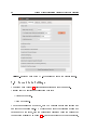
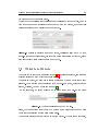
7.1
First tab: Simulation
. . . . . . . . . . . . . . . . . . . . . . . . .
60
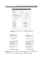
7.2
Second tab: Settings
. . . . . . . . . . . . . . . . . . . . . . . . .
62
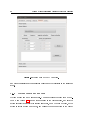
7.3
Third tab: Objects
. . . . . . . . . . . . . . . . . . . . . . . . . .
63
7.4
Fourth tab: Motion . . . . . . . . . . . . . . . . . . . . . . . . . .
65
7.4.1
65
Moving an object . . . . . . . . . . . . . . . . . . . . . . .
VIII
7.5
Odin: a Dynamic Simulation Tool for Robotic Path Planning
7.4.2
Moving joints and motors
. . . . . . . . . . . . . . . . . .
66
7.4.3
Moving robots . . . . . . . . . . . . . . . . . . . . . . . . .
67
Fifth tab: Joints . . . . . . . . . . . . . . . . . . . . . . . . . . . .
69
8 The GUI Core
71
8.1
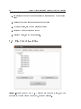
Reading a le
8.2
Processing problem les
8.2.1
8.3
. . . . . . . . . . . . . . . . . . . . . . . . . . . . .
. . . . . . . . . . . . . . . . . . . . . . .
71
Processing shapes . . . . . . . . . . . . . . . . . . . . . . .
74
Increasing path resolution
. . . . . . . . . . . . . . . . . . . . . .
9 Costs Analysis
9.1
71
76
77
Lines of code
. . . . . . . . . . . . . . . . . . . . . . . . . . . . .
77
Line count . . . . . . . . . . . . . . . . . . . . . . . . . . .
77
9.2
Commercial licenses . . . . . . . . . . . . . . . . . . . . . . . . . .
78
9.3
Total cost
78
9.1.1
. . . . . . . . . . . . . . . . . . . . . . . . . . . . . . .
10 Results
79
10.1 Collisions without contacts . . . . . . . . . . . . . . . . . . . . . .
10.1.1 Observations
79
. . . . . . . . . . . . . . . . . . . . . . . . .
80
10.2 Collisions with contacts . . . . . . . . . . . . . . . . . . . . . . . .
81
10.3 Grasping . . . . . . . . . . . . . . . . . . . . . . . . . . . . . . . .
83
10.3.1 Observations
. . . . . . . . . . . . . . . . . . . . . . . . .
84
Conclusions
87
Future Work
89
Bibliography
93
A User Manual
97
A.1
Installation
. . . . . . . . . . . . . . . . . . . . . . . . . . . . . .
97
A.2
Starting
. . . . . . . . . . . . . . . . . . . . . . . . . . . . . . . .
98
Odin: a Dynamic Simulation Tool for Robotic Path Planning
IX
Glossary
• API - Application Programming Interface
A specication containing a set of routines, protocols, and tools for building
software applications [1].
• BSD Licenses - Berkeley Software Distribution Licenses
A family of permissive free software licenses.
• CFM - Constraint Force Mixing
An
ODE
parameter that allows to soften constraints in a simulation.
• DOF - Degree of Freedom
Is the number of independent parameters that dene a conguration of a
system.
• DOM - Document Object Model
A cross-platform and language-independent convention for representing and
interacting with objects in HTML, XHTML and XML documents [2] in a
tree structure.
• ERP - Error Reduction Parameter
An
ODE
parameter that denes which portion of joint errors will be xed
in a time step [3].
• FPS - Frames Per Second
A Hertz equivalent frequency unit:
1f ps = 1Hz .
• GUI - Graphical User Interface
A type of user interface that allows users to interact with electronic devices
X
Odin: a Dynamic Simulation Tool for Robotic Path Planning
using images rather than text commands.
• LGPL - Lesser General Public License
A free software license published by the Free Software Foundation (FSF),
compromising between the strong-copyleft GNU GPL and permissive licenses such as the BSD licenses.
• ODE - Open Dynamics Engine
An open source, high performance library for simulating rigid body dynamics written in C/C++ [4].
• OpenGL - Open Graphics Library
A cross-language, multi-platform API for rendering 2D and 3D computer
graphics [5].
• PQP - Proximity Query Package
A library for performing proximity queries on a pair of geometric models
composed of triangles [6].
• ROS - Robot Operating System
An open-source, meta-operating system that provides the message-passing
between processes, and package management [7].
• RPC - Remote Procedure Call
An inter-process communication that allows a computer program to cause
a subroutine or procedure to execute in another address space, also called
Remote Method Invocation [8].
Odin: a Dynamic Simulation Tool for Robotic Path Planning
XI
Preface
This project was born within the scope of the
Kautham Project, a robot simulation
toolkit for motion planning and teleoperation guiding software package developed
in the Institute of Industrial and Control Engineering (IOC), at the Universitat
Politècnica de Catalunya (UPC).
As dened in [9], the
Kautham Project
is a simulation tool conceived both as an
aid for the development of robot motion planners and as aid for the teleoperation
of robots using haptic devices. It provides the user with an easy way to model and
visualize the problem, with collision-detection and sampling capabilities, basic
planners and communication modules, among others.
Odin project was indeed born as a feature to be integrated in the next
Kautham Project 's release. This has inuenced the choice of some of the tools
used to create this project, C++ as the programming language to begin with,
CMake as the make system, Coin3D as the graphic library, etc.
One of the most evident inuences can be seen in the user interface: since Kautham
already has a working Graphical User Interface, Odin 's one is going to be the
The
rst thing to be dismantled and incorporated. That explains why it can open
Kautham 's
structured problem les, and why it may not be as sophisticated as
the other parts.
There is another inuence in the collision detection system. In fact,
Kautham
PQP -based collision detection engine. Thus, in order to make
the package lighter and simpler, Odin has been developed to provide also the
same kind of collision detection provided by PQP.
But the main interest of Odin is the other type of collision handling: the one
already provided a
that's integrated with the rigid body dynamics simulator and a 3D physics engine.
XII
Odin: a Dynamic Simulation Tool for Robotic Path Planning
XIII
Odin: a Dynamic Simulation Tool for Robotic Path Planning
Introduction
The purpose of this document is to describe the
Odin
project, by showing its
structure and its main features.
The rst chapter will describe the motivations behind this project, the ideas
that inspired it and the requirements to be met.
The second chapter will give an overview of the software involved, with enough
detail to explain why it is important and which limitations it brings.
Odin
is a modular, standalone software package composed by three indepen-
dent modules communicating over a peer-to-peer network. These modules are
the graphical user interface, the viewer and the virtual world. Each module consists of two major classes: a core and a
ROS
layer. The core includes the module's
specic activities, performs calculations and processes data. The
ROS
layer works
as a portal to access the core, and deals with communication, externalization of
results and performs a rst level incoming data processing.
The third chapter will describe
Odin 's ROS
network and will give an idea of the
software general macro structure. But from the third chapter on, the software
structure will be explained in detail.
The rst module analyzed is the most important and irreplaceable: the
World
module. A chapter will be dedicated to the
ROS
layer, and the subse-
quent will cover the core. One chapter will be dedicated to the
but nonetheless tricky. Two chapters will cover the
GUI
Virtual
Viewer,
simpler
module, the last also
chronologically speaking.
The nal chapters will cover cost and environmental analysis, an analysis on obtained results, and a section on future work.
Since this is a software project, an extensive
provided in the attached compact disk.
Doxygen HTML
documentation is
XIV
Odin: a Dynamic Simulation Tool for Robotic Path Planning
Odin: a Dynamic Simulation Tool for Robotic Path Planning
1
Chapter 1
Purpose
Most of motion planning software packages are based on probabilistic path planning, random tree exploration, collision detection and other techniques.
The aim of this work is to create an additional tool for these packages: a rigid
body dynamics simulator that works in parallel with a collision detection engine.
But in order to be attached and integrated to any software kit, the project has
to be modular, multi-platform and open source coded.
On the other hand it has to be a stand-alone program to be distributed. Yet its
parts have to be detachable, so that users can just dispose of what is not needed
and replace it with their own solutions.
Therefore the project is structured in three individually designed independent
parts, loosely coupled at runtime: the virtual world, the user interface and the
viewer. This distributed framework of processes communicates through messages
and service calls in a
Robot Operating System
environment, so that future users
can easily replace any part at any time by just integrating their code with communication features, that is just by adding a few lines of code.
The project has been thought to be used as a testing tool to validate a movement
path in a virtual environment, but as well to help calculating new paths, by integrating its capabilities with a random tree exploration algorithm that studies
the evolution of an element colliding with the environment.
2
Odin: a Dynamic Simulation Tool for Robotic Path Planning
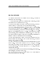
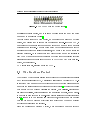
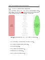
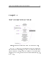
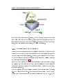
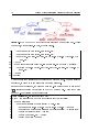
1.1 Structure
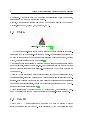
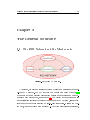
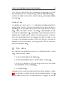
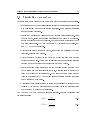
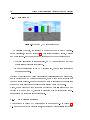
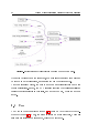
Figure 1.1:
The ow of information in
Odin.
At runtime, the program works in a peer-to-peer network, comprising three
nodes: the
GUI,
GUI, the Virtual World
and the
Viewer. The user interacts with the
dening every detail of the situation to be simulated, like objects, con-
straints, kind of collision handling and other parameters. The
information into messages and service calls and sends it to
GUI converts this
the Virtual World
node. This node creates the scene and actually runs the simulation. It attends
any call from the
GUI
and periodically publishes the simulation results into topic
nodes. At the same time, whenever an object is created or removed, the
World
node calls the
Viewer
Virtual
for the creation or removal of the object in the
viewer's scene.
The
Viewer
will pop up a window containing a 3D visualizer and build a scene
according to the information coming from the
Virtual World.
This node sub-
scribes to the simulation results topics to get information about the situation of
the world. This information is used to maintain the viewer's scene up to date by
3
Odin: a Dynamic Simulation Tool for Robotic Path Planning
updating object transformation data and collision data when required.
A conceptual diagram is shown in gure 1.1.
1.2 Requirements
The requirements to be met were dened thinking about what would be useful
for the
Kautham Project, but at the same time having a standalone, independent,
modular project. Hence the program must be capable of:
•
Simulating physics in scenes and problems built by the
Kautham Project,
with the possibility of moving the robots around and see how they interact
with the rest of the world.
•
Detecting collisions among objects, identify them and, optionally, quantify
the inter-penetration.
•
Integrating collision detection in the physics engine and dealing with collisions in a realistic way.
•
Externalizing all information about the simulation at a user dened variable
rate.
•
Simulating at dierent speeds and precisions.
•
Communicating with other modules through a
•
Reproducing the scene in a viewer, updating the image at
•
Allowing high level user interaction, letting the user the possibility of:
ROS
network.
Building objects, joints and motors.
Applying forces and torques to objects and joints.
Setting and controlling motors.
Setting object position, orientation and velocity.
Loading a scene from a
XML le.
25f ps.
4
Odin: a Dynamic Simulation Tool for Robotic Path Planning
Loading and executing a path for the robots, dened either in position
or in velocity.
Modularity is a very strong requirement. It means complete independence, exibility, separability and replaceability of the three parts (user interaction, calculation and visualization).
5
Odin: a Dynamic Simulation Tool for Robotic Path Planning
Chapter 2
Background Software
This is an introduction to the software packages used in this project. Only an
overview will be given on each tool, and more in-depth elucidations will be given
later on.
2.1 Robot Operating System
Robot Operating System (ROS,
logo in gure 2.1) is a software framework for
robot software development, providing operating system-like services, including
message-passing between processes and package management. It is based on a
graph architecture where processing takes place in nodes that may receive, post
Unix -like system (Ubuntu
such as Fedora and Mac OS
and multiplex messages. The library is geared toward a
Linux
X are
is listed as supported while other variants
considered experimental) [10]. This has prompted the author to immedi-
ately start developing under an
Ubuntu
distribution. The
is a peer-to-peer network of processes, called
nodes,
ROS
runtime graph
loosely coupled at runtime
through a communication infrastructure.
Figure 2.1:
The
Robot Operating System
logo [10].
6
Odin: a Dynamic Simulation Tool for Robotic Path Planning
ROS
Nodes is based on the Message : a data structure
comprising typed elds. The Message can be used in two dierent styles of communication: synchronous RPC -style communication and asynchronous streaming
communication between
of data.
The rst one is a request/reply interaction, and is done via a
dened by a pair of
Service,
which is
Messages : one for the request and one for the reply.
The second one is a publish/subscribe communication style, which decouples the
production of information from its usage. The data streams from the publisher
Node
Topic, a bus that buers up the Messages. Other Nodes can then subscribe to that Topic and read the Messages.
ROS package management features were utilized to organize the project in ve
to a
packages:
• Messages,
• Services,
containing all message templates.
containing all the services' message templates.
• VirtualWorld,
• Viewer,
• GUI,
containing the 3D physics simulator.
containing the viewer.
containing the graphical user interface.
Each package includes a le named
Manifest,
that contains information about
Stack, called Odin
sharing of Messages and
compilation specications. These packages are organized into a
(which also contains its
Manifest ),
to improve code
Services, and to simplify code distribution [7]. ROS is released under the terms
of the BSD license, and is an open source software. Although the last distribution
Fuerte Turtle was released in April 2012, the one used is the previous one, released
in August 2011: Electric Emys [11].
2.2 Open Dynamics Engine
The
Open Dynamics Engine (ODE ) is an open source, high performance physics
engine. It is composed of a rigid body dynamics simulation engine integrated with
7
Odin: a Dynamic Simulation Tool for Robotic Path Planning
Figure 2.2:
The
Open Dynamics Engine
logo [3].
a collision detection engine, and it is also a popular choice for many computer
games and 3D simulation tools [4].
Another option could have been
Bullet,
a more recent open source 3D physics
engine, and despite that it looks more powerful and feature-rich than
ODE,
it
was discarded because its fast growing and recent age meant a rawer and less
extensive documentation. A poorly documented but powerful software might be
a reasonable choice for a skilled professional, but would make a poor choice for
research purposes. An important fact that helped decide among the libraries is
that Open Dynamics Engine is the library of choice for other existing robotics
simulation software packages like
OpenRave
of
OMPL (in OMPL it is only sup-
ported, not integrated).
ODE
is free software, licensed under the
LGPL.
2.3 The Kautham Project
The
Kautham Project
is a simulation tool developed at the Institute of Industrial
and Control Engineering (IOC), Universitat Politècnica de Catalunya (UPC). It
is conceived both as an aid for the development of robot motion planners and as
an aid for the teleoperation of robots using haptic devices [9]. It provides the user
with an easy way to model and visualize the problem, with collision-detection and
sampling capabilities, basic planners and communication modules, among others.
It has been implemented as an open-source project following the directives given
in [12]. Its aim is to be a research and teaching tool, conceived as a compromise
between the need to program everything from scratch and the use of abstract
middleware available in the Internet.
Since the beginning of
Kautham Project,
much importance has been given to
8
Odin: a Dynamic Simulation Tool for Robotic Path Planning
modularity. A next step will be a complete modularization of its components,
integrating
ROS
as a communication device.
Besides, many software choices are due to the packages used in the
Kautham
Project, like CMake, Coin3D, Qt, PugiXML, PQP.
2.4 CMake
Figure 2.3:
CMake logo [13]
CMake is an open-source system that manages the build process in an operating system and in a compiler-independent manner. Nevertheless it is designed to
be used in conjunction with the native build environment: being it
Xcode, Microsoft Visual Studio
Make, Apple 's
or others [13].
The build process is controlled by creating one or more conguration les placed
CMakeLists.txt. They contain simple commands that are
used to generate standard build les (e.g. Makeles on Unix ) which are used in
in each directory, called
the usual way.
This way
CMake generates a native build environment that compiles source code,
creates libraries, generates wrappers and builds executables in arbitrary combinations. It is designed to support complex directory hierarchies and applications
dependent on several libraries, that is why it integrates perfectly with
ROS
pack-
ages and stacks le organization [10].
CMake is integrated by default in the ROS build system, but was already Kautham Project 's build system of choice because of its cross-platform features.
2.5 Coin3D
Coin3D
is a
C++
object oriented 3D graphics
layer of programming for
OpenGL.
API
used to provide a higher
It is developed by the Norwegian company
9
Odin: a Dynamic Simulation Tool for Robotic Path Planning
Figure 2.4:
Kongsberg's Coin3D logo [14]
Kongsberg Oil & Gas Technologies
as clone of the 3D
API Open Inventor
[15].
It works by retaining a complete model of the object to be rendered in a tree
structure called scene graph [14]. The scene can be built at runtime but it is
usually built from a le. The le contains data in a tree structure in the
VRML
format, that will be introduced later.
Coin3D
is distributed with both proprietary and
GPL license.
2.6 XML and PugiXML
Extensible Markup Language (XML)
is a markup language that denes a set
of rules for encoding documents in a format that is both human-readable and
machine-readable [16]. It has been used since the beginning of the
Project
Kautham
to create the problem description les. This les describe a scene with a
robot and some obstacles, addressing to
VRML
les for shape and appearance
descriptions of the single parts and objects.
PugiXML is a library for fast, convenient and memory-ecient processing of
XML les. It consists of a non-validating XML parser which constructs a Document Object Model (DOM ) tree and enables traversing and modication [17]. It
is used for parsing and processing problem les.
PugiXML is distributed under the MIT
license.
2.7 VRML and Qooliv
VRML (Virtual Reality Modeling Language ) is a standard text le format (with
the *.wrl extension) for representing 3-dimensional interactive vector graphics.
In these les it is possible to specify vertices and edges for a 3D polygon along
10
Odin: a Dynamic Simulation Tool for Robotic Path Planning
with the surface color, shininess and so on [18]. They are used in this project to
describe shape and color of some objects.
Both languages are open standards.
Qooliv, whose name is a portmanteau of cool and inventor , is a VRML-le
reader and viewer based on Coin3D 's SoQtExaminerViewer. It has been developed in the IOC and has been inspiration and a starting point for Odin 's viewer.
2.8 Qt
Figure 2.5:
Qt
Qt logo [19]
is a cross-platform application framework that is widely used for develop-
GUI ). It uses standard
C++ but makes extensive use of a special code generator (called the Meta Object
Compiler or simply moc ) together with several macros to enrich the language
ing application software with a graphical user interface (
[20].
Qt
has its own integrated development environment that helps with macros and
and makes the developer work as if the special code had already been generated
(although it is not generated until compile time), but it needs to be compiled in
CMake comes in aid this time too, because it all comes to a few
lines in the CMakeLists.txt to manage the moc and compilation correctly. Qt is
free and open source software, and is distributed under the terms of the GNU
Lesser General Public License (among others)[19].
a certain way.
2.9 PQP
Proximity Query Package
was not actually a software used in this project, but it
deserves to be mentioned because it is the current collision detection library in
the
Kautham Project. This library performs three types of proximity queries:
11
Odin: a Dynamic Simulation Tool for Robotic Path Planning
•
Detects whether two geometric models (triangle meshes) overlap.
•
Computes the minimum distance between two models.
•
Determines whether two models are closer or farther than a tolerance distance.
This library does not make any kind of physics simulation, it just performs collision culling and detection. Therefore,
Odin
and
PQP
can either be put side-by-
side or integrated, substituting the less ecient library with the more ecient
one when it comes to tasks they both perform well, like collision detection.
12
Odin: a Dynamic Simulation Tool for Robotic Path Planning
Odin: a Dynamic Simulation Tool for Robotic Path Planning
13
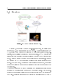
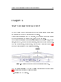
Chapter 3
The General Structure
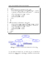
3.1 The ROS Network and the Master node
Figure 3.1:
Odin 's ROS
network.
At runtime, the program consists of three modules communicating over a peerto-peer
ROS
network. The
ROS
network can be seen as a graph of nodes[10],
where each node is a dierent process that performs computation and can com-
Master node provides naming
and registration services to the rest of the nodes in the ROS system, letting them
locate each other before starting a peer-to-peer connection. Besides the Master node, there are three major nodes: GUI_node (the graphical user interface),
municate with other nodes, as in gure 3.1. The
14
Odin: a Dynamic Simulation Tool for Robotic Path Planning
Viewer_node
(the viewer) and
VirtualWorld_node
Master on initialization.
Master, there is another node
(the virtual world). Each one
registers to the
Besides the
that is set up by default. It is the
RosOut, which is the console log reporting mechanism in ROS [10].
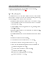
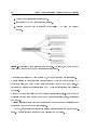
3.2 Communication paradigms
The communication unit is the message. A message is a simple data structure
comprising typed elds, which can contain standard primitives, arrays of standard
primitives, other messages and even arrays of messages. Nodes can communicate
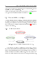
in two ways: through a Publisher/Subscriber semantics (gure 3.2) or through a
Request/Reply paradigm.
3.2.1 Publisher/Subscriber
Figure 3.2:
Model of the Publisher/Subscriber paradigm in
ROS.
A node sends out a message by publishing it to a given topic. A topic is a
named bus which decouples the production of information from its usage, and is
intended for unidirectional, streaming communication. The topic name is used to
identify the content of the message published in it. A node that wants to have
access to the message locates the topic through the
Master, and subscribes to it.
15
Odin: a Dynamic Simulation Tool for Robotic Path Planning
Multiple nodes can publish on and subscribe to a same topic, but they do not
have to be aware of each other's existence.
Every node is connected by default to the
RosOut topic, where it publishes logging
messages.
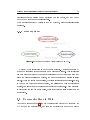
3.2.2 Request/Reply
Figure 3.3:
Model of the Server/Client paradigm in
ROS.
Request/Reply interaction is made through services. A service is dened by
a pair of messages: a request message and a response message. This interaction
can take place only after both nodes have registered to the
Master : the node that
sends the request registers as a client, the one that serves and replies is called
server. While the server must register, the client registration is optional. In fact,
in the Remote Procedure Call mechanism, the calling node does not register as
a client, but simply sends the request and receives the response. This mechanism
is convenient for one time only calls, while for repetitive calls a client is more
appropriate.
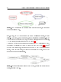
3.3 Communications in Odin
As it can be seen in gure 1.1, the ow of information within
Odin
GUI
node to the
node to the
VirtualWorld,
and from the
VirtualWorld
goes from the
Viewer
16
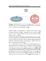
Figure 3.4:
Odin: a Dynamic Simulation Tool for Robotic Path Planning
A more accurate computation graph showing the nodes, the topics and
the service calls in
Odin.
GUI node does not set up any publisher nor server, but just
clients. The Viewer, on the other hand, sets up servers and subscribers. In the
middle there is the VirtualWorld node, that sets up clients, servers and publishers.
node. In fact, the
A more accurate representation is shown in gure 3.4.
Another way to see the computation graph is given by a
ROS tool called RxGraph,
that allows to visualize the graph at runtime as shown in gure 3.5. Because
of their ephemeral nature, services are not shown:
RxGraph
detects the servers
indeed, which are permanent, but since they are inside the nodes, they do not
appear in the graph representation.
Figure 3.5:
Computation graph caught with
topics, including
RosOut.
RxGraph, showing the nodes and the
17
Odin: a Dynamic Simulation Tool for Robotic Path Planning
3.3.1 GUI and VirtualWorld interaction
The communication between the
GUI
node and the
VirtualWorld 's
is Server/-
Client based. As shown in gure 3.6, a conspicuous number of services is needed
to grant the user full action on the simulation. The services are:
Figure 3.6:
Services called from the
GUI
and replied by
VirtualWorld.
•
New Scene: destroy the current scene and create a new one.
•
Set World: set general simulation parameters.
•
Set Step: set step sizes.
•
Step Once: run one simulation step.
•
Start: start/stop the simulation.
•
Build Object: create a single object.
18
Odin: a Dynamic Simulation Tool for Robotic Path Planning
•
Build Composite: create a composite object, that is an object made of simple
primitive geometries.
•
Build Entity: build a set of objects with some common features.
•
Remove Object: destroy a single object.
•
Set Joint: create a joint between two objects.
•
Set Motor: add a motor to a joint or an object.
•
Set Position: set object position.
•
Set Velocity: set object or motor velocity.
•
Set External Force: apply a force or a torque on an object.
•
Set Joint Force: apply a force or a torque on a joint.
A deeper insight on the true meaning of these services will be given when addressing the nodes themselves in the next chapters.
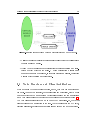
3.3.2 VirtualWorld and Viewer interaction
The
VirtualWorld
node has to externalize all the information it produces, and
does it using both paradigms: Client/Server for the initialization of the scene
and the creation of new objects, and Publisher/Subscriber to update the scene
information and the system spatial layout (gure 3.7). Services are used to create
the scene and put objects in it, as well as to remove them. The ones called by the
VirtualWorld
node and serviced by the
Viewer 's are:
•
Viewer Remove Object: remove an object from the scene.
•
View Object: add a new object to the scene.
•
New Scene: reset the scene.
Subscriptions to the topics allow the
Viewer
to have updated information about
the state of the world, needed to render the scene properly.
19
Odin: a Dynamic Simulation Tool for Robotic Path Planning
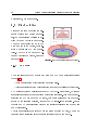
Figure 3.7:
•
Information exchange between
VirtualWorld
and
Viewer
nodes.
Collided (message: Collided): contains a list of all objects that collided since
the last message was sent.
•
World Update (message: SpaceDistribution): contains position and orientation of every object in the scene. A Space Distribution message is an
example of an array of messages, in this case Situation messages, describing
a single object position and orientation.
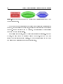
3.4 Node Structure and Class Architecture
Every module in
Odin is a dierent process, a node, that both communicates and
computes. To improve modularity, code reuseability and portability, every module
has been divided in two main parts: a
Portal
class dealing with communications
Core class dealing with specic node processing computations (gure 3.8).
The Core class is instantiated as a member of the Portal class. So, the Portal
grants access and communication to the core. The Portal is in fact the ROS layer,
and a
contains all servers, publishers and subscribers and sets up the node on start up.
20
Odin: a Dynamic Simulation Tool for Robotic Path Planning
Figure 3.8:
Each node is composed by a
Portal
(communication layer) and a
Core
(computation layer).
Core is the computation layer that deals with actual specic calculation for
VirtualWorld ) or rendering
(Viewer ). It does not link to any ROS library, but rather links to other classes
The
the node, such as dealing with les (gui), simulating (
that help with its process issues.
In the following chapters, every module will be analyzed extensively. For every
module, the rst part to be analyzed will be the
Portal,
then the
Core
and
nally the other supplementary classes. The next chapter starts with the most
complicated and irreplaceable module:
VirtualWorld.
21
Odin: a Dynamic Simulation Tool for Robotic Path Planning
Chapter 4
The Virtual World Portal
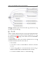
Figure 4.1:
From the
First level of collaboration diagram for
GUI
VirtualWorld node is a set of
To the Viewer it is a client that
point of view, the
grant control over the simulation.
VirtualWorld::Portal.
servers that
asks for the
creation of scenes and objects, as well as a publisher to the simulation related
topics. It is the key module, and its three most important classes are:
tal
and
Core.
Main, Por-
22
Odin: a Dynamic Simulation Tool for Robotic Path Planning
The rst class produces the executable that initializes, runs and closes a
Virtual-
World::Portal instance.
The Portal is the ROS layer that covers the Core class, which actually runs the
simulation. It instantiates the Core and sets up the VirtualWorld ROS node (gure 4.1). But most of all, it manages and controls the simulating core, by telling
it when, how, what and how much it has to simulate.
As a matter of fact, the
Portal
class has only three public member functions:
initialize, run and close. Besides these three, every other member is private.
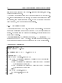
4.1 Initialization
The
init
function rst initializes
ROS,
the
Core,
sets up the servers and the
publishers and nally sets a default value to all those variables that can be dened
by the user, but are indispensable for the program to run, such as the message
rate and the step sizes (gure 4.2). When initialization is over, the program enters
the running loop.
4.2 Servers
The servers cover all those services that allow (through the
GUI ) user interaction
with the simulation, like:
•
Setting simulation parameters: gravity, ERP, CFM, maximum angular speed,
maximum correcting velocity, contact surface layer, damping values and
thresholds.
ODE 's steps between messages and cycle rate.
•
Setting step sizes, number of
•
Creating/destroying objects, like spheres, cylinder, boxes, composites or
triangular meshes.
•
Creating joints and motors.
•
Adding/removing forces, torques on objects or joints.
Odin: a Dynamic Simulation Tool for Robotic Path Planning
Figure 4.2:
First level of call graph for
backs are visible as
of
ROS.
23
VirtualWorld::Portal::init. All server call-
Portal functions, but are private and can be used only because
24
Odin: a Dynamic Simulation Tool for Robotic Path Planning
•
Setting desired goal speeds on a list of motors.
•
Setting objects position and speed values.
Most of these servers' callback function are not very interesting, since they may
just set a value or wrap another
Core
function that will be analyzed later. But
those described in the following sections deserve a special attention, because it is
where
Portal
shows that it is not a mere access gate to the
Core,
but rather a
manager and an interpreter.
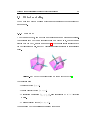
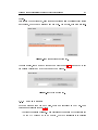
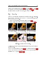
4.2.1 Creating and destroying elements
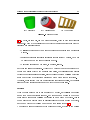
Objects
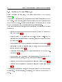
Creating a new object involves a series of checks: name collision, quaternion consistency, non zero mass. If one of these checks fails, the object is not built and a
message is printed on the system out.
An additional check on the number of parameters determines whether the object
geometry is a simple primitive (sphere, cylinder or box as in gure 4.3a) or if it
is a triangle mesh (gure 4.3b), and the corresponding
Core
function is called.
Once the object is created, it has to appear in the viewer's scene.
Odin
identies its objects through user dened strings. These IDs must match
those in the viewer's scene, so when an object is created (or destroyed),
takes care of calling the
Viewer 's
Portal
object creation (or destruction) service using
the same ID that appears in the simulation. This separation between the
and the
Viewer
GUI
makes the communication between the virtual world and the
visualizer more consistent and reliable.
The process of object destruction mirrors the one of creation: the object is
rst removed from the
Core,
then a call is made to the
Viewer
to prompt its
removal from the rendering scene.
Composites
A composite is an object whose geometry is neither a simple primitive, nor a
triangle mesh. Its geometry can otherwise be dened as a sum of primitives (gure
25
Odin: a Dynamic Simulation Tool for Robotic Path Planning
(a) A primitive
(b) A triangle mesh
Figure 4.3:
(c) A composite
Simple objects
4.3c). A table, for example, can be modeled as a large, thin box with four cylinders
as its legs. This way of representing the object gives several advantages over the
triangle mesh representation:
•
Collision detection and dynamics work faster on primitives than on triangle
meshes.
•
Inertia matrices are calculated internally for primitives by default, but must
be user dened in the case of triangle meshes.
•
Rendering is faster and the scene, in general, lighter.
But there is a little complication. While the
ODE
library wants composites to be
dened as a single object with multiple geometries, the visualizer often prefers
to treat geometries as single entities, since it will not perform collision detection
nor it has to think about inertia matrices and other dynamics computations.
Core composite creation functions are called, Portal calls
standard object creation services on the Viewer for each primitive.
Therefore, while specic
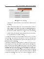
Entities
When two elements of a robot arm are linked by a joint, any collision happening
among them is automatically ignored. But there are some cases in which one
would like to ignore each collision happening among a group of objects. This is
when Build Entity Service becomes useful: it allows to create a group of objects,
and dene whether they collide or not among themselves (gure 4.4).
The request message contains a vector of simple objects, a vector of composites
26
Odin: a Dynamic Simulation Tool for Robotic Path Planning
Figure 4.4:
An entity.
and an internal collision ag. The callback function processes this vector by passing its elements to the competent callback functions, but in the meantime stores
their IDs in a list. Once every object is built, the callback function passes this
list to
Core
for it to deal with the collision ags.
4.2.2 Joints, motors, forces and torques
Adding forces and creating joints is a more interesting subject from the point of
Core, and it will be dealt with later on. But there is an aspect of it
that is dealt with within the Portal, and that is identication.
In fact, everything in Odin is addressed through a string ID, from objects to
view of the
forces. In all these cases the user can give a name to the element he is creating,
but when he does not,
Portal
baptizes it for him.
If it is a joint, the name created is based upon the joint type and the IDs of the
objects involved (e.g. if it is a ball joint between body1 and body2 the ID will
be 0:body1& body2 ).
A similar thing happens when a motor is created, with the only dierence that
the new name will start with motor:.
But joints and motors are unique, that is there can only be one among two objects
(more than one joint is either redundant, zeros the degrees of freedom or it is just
a bad joint type choice). Forces and torques on the other hand can sum up and
be applied to the same joint or object. Thus, when adding a force or a torque,
the algorithm has an additional twist: every force added has a number at the end
of the ID. When a new force is added in the same place, the function looks for an
unused number among the forces present, and uses it to baptize the new force.
27
Odin: a Dynamic Simulation Tool for Robotic Path Planning
4.3 Publishers
Publishers are those members that, once in a cycle, manage to collect some information about the ongoing simulation and publish it on their respective topics.
Those topics can be subscribed by any node, but are particularly a feed to the
Viewer
node, that has to update the rendering scene.
4.3.1 Objects position and orientation
The main topic
VirtualWorld
publishes on is the so called
Space Distribution. It
contains all up-to-date geometries' position and orientation. This information is
gathered before each publication from the
Core, which in turns extracts it from
the simulation.
The information is about geometries, not objects, which do not coincide in the
case of composite objects. As it has been previously said,
ODE
and viewer models
are dierent in the case of composites. Therefore, when publishing the position
of a composite, the
VirtualWorld
node cannot give the position and orientation
of the whole body, but has to tear it apart and give separate data about every
single part.
The solution adopted to solve this divergence consists in letting the user dene
names for the composite parts, and not the whole body name.
Portal
builds the
whole object name using the part names separated by the symbol >, and uses
this name as the object's identier in the simulation: e.g. >part1>part2. When
preparing the message, however,
Portal disassembles the object's name, and sends
transformation messages for each geometry coupled with that part's name. This
way, the viewer will never know whether two elements are part of the same object
or not, but it will render them correctly nonetheless.
4.3.2 Colliding objects
Among the parameters, there is a ag that determines whether collisions inuence
the dynamics or not. In one case objects collide, bounce and slide; in the other
case, they penetrate into each other constrained only by the joints that tie them
28
Odin: a Dynamic Simulation Tool for Robotic Path Planning
together. This kind of simulation is said to be contact-less, because no contact
constraints are created during the simulation.
In case of a contact-less simulation, collision handling consists in detecting which
objects are colliding and in reporting them on a list. This task is made by the
Core
Portal, on the other
to the Collided topic.
and will be analyzed in the following chapter. The
hand, publishes a message containing this list of objects
This topic will be subscribed by the
Viewer,
that will handle this information
properly.
4.4 Running loop
In the running loop, the program does basically three things:
1. May or may not advance the simulation.
2. Publishes the state of the world.
3. Processes and replies all Service calls.
4.4.1 Simulation advancing from Portal
Usually, one would like to have many simulation steps in a
That is because the
ODE
Portal
running cycle.
library becomes more exact and reliable as the simu-
lation step becomes smaller. Hence the standard procedure is to split the cycle
ODE steps. For this reason, advancing the simulation means
stepping forward the Core 's simulation a number of times (see 4.5). For default
step time in smaller
step values see table 4.1.
Simulation automatic advancing is determined by a ag named simulate. This
ag is changed through the Start Service, which allows to start and stop the
simulation at any time.
Automatic stepping
When the simulate ag is set to
true,
every
Portal
cycle runs the simulation for
a certain number of steps. In this mode the user can intervene in the simulation
29
Odin: a Dynamic Simulation Tool for Robotic Path Planning
at any time, but will be acting on the simulation as it is running. That means
that if there is gravity and a ball is created, it will start falling immediately.
This mode is perfect to see a system evolve on its own, after initial conditions
have been set.
Stepping at will
The simulate ag might be set to
f alse
while setting the initial conditions of a
system, creating some new object, moving things around or simply just stop the
simulation. But the simulation can advance even if the simulate ag is always
false. This is made through the Step Once Service. This service allows the user
to advance the simulation at will. This is useful when the user wants to run the
simulation only a certain number of times and then stop, or when he wants to
give a set of service calls for every time step. For example, when driving a motor
by feeding it the instantaneous velocity at each time step, one would like the
simulation to stop between velocity commands, in order to give the user time to
react or process information.
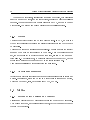
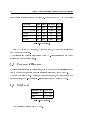
4.5 Step values
Step values are those variables that dene how the simulation is going to handle
time. There are four step values:
•
The time to be simulated in one single step.
•
The number of simulation steps to be taken within a
•
The time to be simulated in one
Portal
Portal
cycle.
cycle, that is the time that passes
in the simulation between publications.
•
The publication rate.
It is easily deduced that the third value is the product of the previous two (gure
4.5). For this reason the callback function hides an interesting algorithm that allows the caller to dene any number of values (from one to four), and the function
30
Odin: a Dynamic Simulation Tool for Robotic Path Planning
will calculate the remaining and return the nal values. In case of conicting values, precedence is given to simulation step and
Portal
step size, to the detriment
of the number of steps in a Portal cycle.
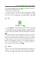
Figure 4.5:
Step values diagram. In red, the time simulated in a
green, the actual time simulated in a
Portal
cycle. A
Portal
Core
cycle. In
cycle includes the
publication, thus the publication rate is the cycle rate.
As a matter of fact, the simulation time elapsed between
Portal
cycles is not
a member variable, because the other values determine it univocally. But it is
accepted by the Set Step Service: it is just a user friendly variable.
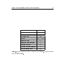
The default step values have been chosen so that one second in the virtual world
equals one second in the real world, as it can be seen in table 4.1
Contact-less collision
f alse
Simulate
f alse
Number of
Table 4.1:
Core
40
steps in a cycle
Publishing rate
25f ps
Simulation time elapsed between cycles
0.04s
Simulation step (Core)
0.001
Default values for
VirtualWorld::Portal
and step sizes for
Virtual-
World::Core.
4.6 Closing
When closing the process the function closes
Core
and shuts down the node.
When prompted for a new simulation, it just restarts
service on the
Viewer.
Core
and calls the same
31
Odin: a Dynamic Simulation Tool for Robotic Path Planning
Chapter 5
The Virtual World Core
The very beating heart of this project is the dynamics simulation engine inside
VirtualWorld node: the VirtualWorld::Core class.
While Portal deals strictly with ROS features, Core performs the specic actions
the
of the module: creates the virtual world, acts on it and simulates.
Core
works symbiotically with four smaller classes which perform easy, specic
tasks, such as body, geometry and joint creation, or force and torque management.
They are
BodyManager, JointManager, BodyForce
and
JointForce
(gure 5.1).
Each one will be analyzed in the following sections.
Figure 5.1:
The
Core
Detail of dependency graph for
class is initialized by
Portal
by calling
5.2). This function involves the following tasks:
1. Initialize the
ODE
library.
VirtualWorld::Core.
VirtualWorld::Core::init
(gure
32
Odin: a Dynamic Simulation Tool for Robotic Path Planning
2. Create a new simulation environment.
3. Instantiate body and joint creation classes.
4. Allocate the data that is required for accessing ODE from the current
thread.
Figure 5.2:
Call graph for
VirtualWorld::Core::init. The space, the world and the
joint group are parts of the new simulation environment.
After all these tasks have been performed, the thread is ready for simulation.
The simulation is an integration process through which time is advanced by a
given step size, and every object state is adjusted for the new time value. It
involves two separate processes: rigid body dynamics simulation and collision
detection.
Rigid body dynamics deals with the object's dynamic properties. It computes the
evolution of the system using the laws of motion considering joints, constraints
and forces.
Collision detection deals with the object's shape and denes new constraints that
are passed back to the dynamic simulator.
Anyway, no simulation makes sense unless there is actually something to simulate. The rst section will cover object creation and modeling.
33
Odin: a Dynamic Simulation Tool for Robotic Path Planning
5.1 Object modeling
Open Dynamics Engine models an object as a combination of two concepts: body
and geometry.
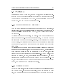
5.1.1 The body
A body is a set of data, some of them are variable and some others are constant.
Conceptually each body has a coordinate frame embedded in it, that moves and
rotates with the body, as shown in gure 5.3. The frame's origin corresponds to
the body's center of mass, and body variables are always referred to this reference
point.
Figure 5.3:
The body coordinate frame moves with the body[3].
The variables are:
•
Position vector
•
Linear velocity vector
•
Orientation quaternion
(x, y, z).
(vx , vy , vz ).
(qw , qx , qy , qz ),
also represented by a
matrix.
•
Angular velocity vector
(wx , wy , wz ).
The remaining body properties are constant over time:
3×3
rotation
34
Odin: a Dynamic Simulation Tool for Robotic Path Planning
•
Mass value.
•
Inertia, a
3×3
matrix.
5.1.2 The geometry
A geometry is a set of data describing shape,
position and orientation (Fig. 5.4). It is associated with a position and an orientation, but
has no dynamic properties, such as velocity or
mass.
In order to move during the simulation, a geometry must be attached to a body. This way
both share position and orientation, and to-
Figure 5.4:
The geometry: shape.
gether describe the object.
5.1.3 Objects
ODE has one body, but can have multiple geometries. Therefore,
in ODE (and in Odin ), body and object are basically equivalent concepts.
Every object in
There are ve types of objects that can be created:
•
Spheres;
•
Cylinders;
•
Boxes;
•
Composites;
•
Triangle meshes.
The rst three are simple primitives, and are built using native
ODE
functions
that automatically determine the inertia matrix from shape and total mass.
35
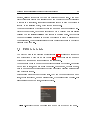
Odin: a Dynamic Simulation Tool for Robotic Path Planning
Composites
A composite is an object made of multiple primitive geometries (gure 5.5).
ODE
allows this kind of objects but they have to be built in a certain way to work well:
1. First, create the body and attach it
to the rst geometry, as if it was a
normal object.
2. Then, for each part:
(a) Create the geometry.
Figure 5.5:
(b) Create the mass.
posite
(c) Attach the geometry.
A table built as a com-
made
of
box
and
cylinder
primitives.
(d) Move and rotate the geometry to its correct position respect to the
body's center of mass.
(e) Move and rotate the mass.
(f ) Add the mass to the body's mass.
These tasks are performed automatically by the
builder:
Core, with the help of the body
BodyManager.
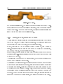
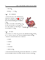
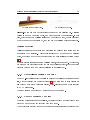
Triangle meshes
A triangle mesh (gure 5.6) is dened by two
vectors: a vertex vector that reports the position of the shape boundary points, and a index
vector that tells how those vertices are ordered
to create triangles.
While for primitives and composites the inertia matrix is automatically determined by the
library, in the case of triangle meshes it is not.
If the user does not dene an inertia matrix,
the identity matrix will be set by default.
Figure 5.6:
Triangle mesh: palm
of a robotic hand.
36
Odin: a Dynamic Simulation Tool for Robotic Path Planning
5.1.4 Objects in the simulation
The dynamics simulation engine uses body information altogether with the movement limitation given by joints and other constraints. In fact, rigid body dynamics
engine does not deal with shapes or geometries, but deals only with bodies.
The collision detection engine, on the other hand, deals uniquely with geometries.
At every time step it gures out which bodies touch each other and returns the
resulting contact point information. A
Core
function then uses that information
to dene new constraints by creating contact joints between bodies.
The rigid body dynamics simulator works with a world, an element that contains all the bodies and constraints. On the other hand, the collision detection
engine works with a space, that contains all geometries. Both these elements
are created on initialization.
5.1.5 The BodyManager class
VirtualWorld is managed by the BodyManager class. A BodyManager instance is present in Core as a private member, and creates the objects
Object creation in
in the world and space given at the time of construction.
This class was created in an attempt to simplify the
Core
class, and to provide
tools to make object and geometry creation simpler.
In fact,
BodyManager
handles the creation of bodies and geometries by requir-
ing only essential information and guring out the rest. For example the kind of
primitive does not have to be explicit, because it is determined by the number of
shape parameters: if there is one parameter it is going to be a sphere's radius; if
there are two they will be a cylinder's radius and length; if there are three they
will be the sides of a box, and if there are more, they are going to describe a
triangle mesh.
BodyManager
can also create body-less geometries, that can be used to represent
objects that never move but collide with the rest of the world.
37
Odin: a Dynamic Simulation Tool for Robotic Path Planning
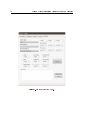
5.2 Simulation parameters
There are a few parameters that can be set to improve the quality of a simulation.
•
Step size: most of dynamics calculation involve Taylor transformation's rst
members instead of the actual motion equations. Thus accuracy increases
as the step size decreases.
•
Linear and angular damping: avoid that objects drift indenitely. After
each time step, linear and angular velocities are compared to a threshold.
If they are bigger than that threshold, they are reduced accordingly to the
damping parameters. They can be set in a
in a
•
[0, +∞)
[0, 1]
interval for the value, and
for the threshold.
Gravity: it is dened through a vector, thus giving the possibility to decide
direction, intensity and versus.
•
Contact Surface Layer: it is the depth an object can sink into another
before contact is made. Even a very small value can help preventing jittering
problems due to contacts being repeatedly made and broken.
•
Error Reduction Parameter: when for some reason a joint happens to be
out of alignment or a constraint is not met, a special force is activated to
bring the bodies back into alignment. The Error Reduction Parameter is a
value in the interval
[0, 1]
that determines the fraction of error this force
has to correct in a time step.
•
Constraint Force Mixing: allows to soften the constraint by letting it to be
violated by an amount proportional to the value times the restoring force
that is needed to enforce the constraint.
The CFM and ERP can be used to simulate a spring-damping constraint with
the following rule:
ERP =
hkp
hkp + kd
(5.1)
CF M =
1
hkp + kd
(5.2)
38
Odin: a Dynamic Simulation Tool for Robotic Path Planning
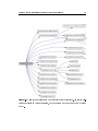
5.3 Joints and JointManager
where
h
represent the step size,
kp
the spring constant and
kd
the damping
constant[3].
A joint in
ODE
is represented as a constraint that imposes a relationship between
two bodies. At each time step, all the joints are allowed to apply constraint forces
to the bodies they aect. These forces are calculated by assuming that the bodies
have to move in such a way to preserve all the joint relationships.
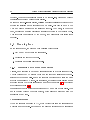
There are several kinds of joints, each one constraining a dierent set of degrees
of freedom:
•
Ball and socket: keeps the anchor point still in the frame of reference of
each body (gure 5.7a).
•
Hinge: is dened by an anchor and an axis. It is like a ball-socket but
constraints an additional degree of rotation, allowing rotation only along
the axis (gure 5.7b).
•
Piston: a slider that does not constraint rotation along the axis (gure 5.7c).
•
Slider: allows bodies to translate along an axis, but any other degree of
freedom is denied (gure 5.7e).
•
Universal: a cardan joint, like two perpendicular hinges with the same anchor (gure 5.7f).
•
Double hinge: used to simulate vehicle suspensions, is composed of two
hinges connected in series, but with orthogonal axes (gure 5.7d).
•
Prismatic and Rotative: a combination of a slider and a hinge (gure 5.7g).
•
Prismatic and Universal: a combination of a slider and a cardan joint (gure
5.7h).
A joint usually connects two bodies, but it can also connect a body and the static
environment. This case is useful, for instance, to model the moving base of a
robot.
39
Odin: a Dynamic Simulation Tool for Robotic Path Planning
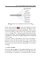
(a) Ball and socket.
(b) Hinge.
(c) Piston.
(d) Double hinge.
(e) Slider.
(f) Universal.
(g) Prismatic-Rotative.
(h) Prismatic-Universal.
Figure 5.7:
in the
The joints are just constraints and do not have a visual representation
Viewer, hence these are just graphical aids to help understand the nature
of each joint [3].
40
Odin: a Dynamic Simulation Tool for Robotic Path Planning
There are two additional, special joint types: the xed joint, that constrains
all DOFs among two bodies, and the contact joint, generated whenever a collision
happens. The rst one is not very well implemented in
ODE, and has to be used
with caution. The second one will be described in the collision section.
5.3.1 Motors
Another thing
JointManager
can do is to create motors. In
ODE,
a motor is a
type of soft constraint that allows the relative velocities between two bodies to
be controlled.
There are two kinds of motors: angular and linear. The user must set the velocity
axes and the maximum force allowed to the motor. Once the desired speed is
set, the motor will try to achieve it in one time step, limited by the maximum
force allowed. The velocity axis, by default is anchored to the rst body, but can
otherwise be anchored to the second body or the static environment.
All motors are initialized with innite force and null speed.
5.3.2 Additional parameters
JointManager
provides functions to set some additional parameters on joints and
motors. For instance, stops can be set on a joint to limit its range of motion,
which can be bouncy, rigid, have customized CFM, ERP etc.
5.4 Motion
5.4.1 Setting object position and velocity
Position and velocity are body properties that are set when the body is created.
They change over time, as the simulation advances, but they can also be changed
through
Core
functions.
41
Odin: a Dynamic Simulation Tool for Robotic Path Planning
5.4.2 Forces and torques on bodies
Besides the forces generated as a result of a constraint or gravity, forces and
torques can be applied to the bodies, for them to take part in the simulation.
The force itself is not added when it is created, but is added at every step, as will
be explained later.
A force or a torque is created by instantiating an
ExternalForce
object, which
is dened by a target body pointer, a magnitude and a direction. The direction
can be given either in the body's frame of reference or the world's one, while the
point of application can be either the center of mass or another point, which can
be given in both frames of reference.
5.4.3 Forces and torques on joints
JointForce
on joints.
ExternalForce 's sibling class that represents forces and torques
The JointForce object's elds are a target joint pointer and a magniis the
tude: it can either be a force on a sliding joint, a torque on a hinge or ball-socket
joint. In the future, it will be possible to add forces and torques on other kinds
of joints, but for now this feature is limited to those three. Since the target is a
joint and not a generic body, no direction information is needed: it is deduced
from the joint data instead.
5.4.4 Using motors
A motor is a type of soft constraint that applies all the force available to reach
the goal speed, without surpassing it. Thus, another way of acting on the bodies
is to create a motor and then control its speed.
On creation,
Force
Core
creates a motor through
JointManager,
object that manages the motor's velocity.
and creates a
Joint-
42
Odin: a Dynamic Simulation Tool for Robotic Path Planning
5.5 Core's simulation step
Actually,
Core does not have a running cycle because Portal
functions to step the simulation. There are two stepping functions,
and
Core 's
contactStep
has, and calls
contactLessStep, that share a common structure:
1. Detect and handle collisions.
2. Add forces and torques to bodies.
3. Add forces and torques to joints and set goal speed on motors.
4. Take a step.
5. Reset unmovable bodies, to prevent unwanted errors.
All external forces and torques are deleted automatically at the end of each step.
That is the reason why they are all added before each step.
As the names suggest, the dierence between the step functions resides in the
way collisions are handled: one creates contacts, the other does not.
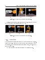
5.5.1 Collision detection
The space
Collision handling is one of the most important features of
Odin. Its mechanism
resides in the space, that is the object that contains all geometries. Among the
space kinds available in the
ODE
library, the one chosen is the multi-resolution
hash table space. It uses an internal data structure that records how each geometry occupies cells of three-dimensional space. This strategy speeds up collision
culling if the cell sizes are accurately chosen, and if objects are not clustered
together too closely. These consideration have made it easy to chose the hash
space over the normal space (and the quad-tree-space, because it is still under
development [3]).
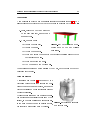
Odin: a Dynamic Simulation Tool for Robotic Path Planning
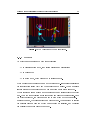
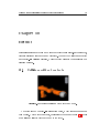
(a) Wire frame overlay view.
Figure 5.8:
43
(b) Bounding box view.
Example of two objects close together but not colliding yet. Collision
culling is made on bounding boxes, and their bounding boxes intersect. In this
case, objects pass both collision culling and bounding box test, but are discarded
when the nal check is performed, that is when the collision points are searched.
Collision detection
Collision culling is the process that shortlists the pairs of geometries that are
more likely to be colliding. This process is followed by a bounding box collision
check, that creams o the best candidates for the nal collision detection (gure
5.8).
The last process consists in nding collision points, if there are any. At this point,
the program can either just record the names of colliding objects, or it can create
contacts between them and handle collisions in a realistic way.
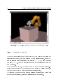
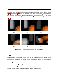
5.5.2 Contact-less collision handling
This
PQP -like collision policy consists in pushing the colliding bodies' names in a
list, without building any contacts (gure 5.9). It means that objects will simply
slip through each other during simulation, inter-penetrating each other just like
in a
PQP
simulation.
The list will then be accessed by another part of the program.
5.5.3 Contact collision handling
This kind of simulation is more realistic, because objects do not slip through each
other but make contact and interact with each other.
This behavior is achieved through the creation of special joints that last only one
44
Odin: a Dynamic Simulation Tool for Robotic Path Planning
Figure 5.9:
Call graph for
VirtualWorld::Core::contactLessCallback.
step: the contact joints (gure 5.10). A contact joint constraints the bodies to
have an outgoing velocity along the contact normal. Theoretically, the contact
normal is the direction along which lies the shortest distance a body has to move,
in order to stop colliding. Actually the one used is an approximation calculated
by an
ODE
function. The
ODE
library, in fact, provides a function that besides
determining if and where a pair of geometries collide, can create a contact joint.
Those joints have to be attached to the colliding objects, and have to be destroyed
after each step.
The maximum number of contacts allowed between a pair of geometries is a
simulation parameter that inuences signicantly the quality of the simulation,
slowing it down at the same time as the number increases. At the same time, a
combination of contact joints can simulate rotation, pivoting and other contact
behaviors.
An example of collision
Imagine a box falling corner-side on a table, colliding inelastically. When the parts
touch, a ball joint is created in order to simulate the rst contact. Within a short
amount of time, the box will fall and the edge will completely touch the surface
45
Odin: a Dynamic Simulation Tool for Robotic Path Planning
Figure 5.10:
A contact joint.[3]
and then a hinge joint is created. Finally, the box will rotate along the hinge axis
and will lay all a side on the surface, thus a plane joint is created: the kind of
joint created depends on the type of collision. Therefore, the more the contact
joints, the more realistic the simulation, on detriment of speed.
5.5.4 Optimizations and exclusions
Frequently there are situations in which collisions detection among some specic
bodies has to be avoided, mostly because it slows down the simulation signicantly
to have bodies permanently colliding. Therefore, a few solutions have been found
to make it possible to exclude some pairs of geometries from collision detection
(an example is given in gure 5.11).
Since most of the data fed to the simulator consists of kinematic chains or trees,
the collision has been optimized in order to ignore collisions between consecutive
objects of a kinematic chain: if two objects are already connected with a joint,
no contact is created.
Another possibility is to avoid collision detection within an entire group of bodies,
e.g. the whole kinematic chain. This function is the one called when an Entity
Service from
Portal
arrives with an internal collision ag set to
f alse.
In this
46
Odin: a Dynamic Simulation Tool for Robotic Path Planning
Figure 5.11:
Robot geometries' bounding boxes will always collide, so it is a smart
move to avoid collision detection among them.
case, a special geometry property is used to avoid collision detection among a
group of geometries.
5.5.5 ODE step
ODE 's
function
worldStep
allows to determinate the dynamic evolution of the
system over the next time step. This uses a big matrix method that takes time
on the order of
m3
and memory on the order of
m2 ,
where
m
is the total number
of constraint rows.
It bases its calculations on rst Taylor's transformation members for quadratic
equations, therefore it is more accurate when the time step is very small. That
leads to repeat its operation many times before reaching any noteworthy advance.
Whenever the simulation run time is considered enough, some information can be
extracted from the simulation, using the features exposed in the following section.
47
Odin: a Dynamic Simulation Tool for Robotic Path Planning
5.6 Information extraction
When
Portal
wants to publish on some topic the results of the simulation, it
has to call a function in
Core
to retrieve it. The most important information
about the simulation is the current position and orientation of each geometry. As
explained in chapter 4, the information published about the state of the world
involves geometries, and not bodies, since that is what is shown in the
In fact, the
Core::getTransformation
Viewer.
function iterates all the geometries, and for
each one it gets its position and orientation.
Another function implemented gets position and speed of every existing joint.
Although this information is published by
mented in
Portal, no subscriber has been imple-
Odin.
The last information that can be retrieved from the simulation is, in case of
contact-less collision detection, a list of colliding geometries. The act of reading
this list automatically clears it, deleting every name on it. This makes sense
because many cycles can happen before this list is read, and the calling class
would like to know about all objects that have collided in the last steps, and not
just in the last one.
5.7 Check functions
As it was explained before,
Core
stores all objects, joints, motors and external
forces in dierent maps, to quickly nd them by their names. Specularly, it has a
complete set of functions to nd the names by their pointers, nd a joint by the
bodies it connects, and check name validity.
5.8 Close
Closing means deleting every body, geometry, joint, forces, space and world, and
clearing every list and register in the class. This function does not stop the main
method, meaning that
lation.
Portal
can call
close
and then
init
just to reset the simu-
48
Odin: a Dynamic Simulation Tool for Robotic Path Planning
49
Odin: a Dynamic Simulation Tool for Robotic Path Planning
Chapter 6
The Viewer
Figure 6.1:
The
Viewer
logo: the Triple Horn of Odin[21].
6.1 Previous versions
Throughout the developing of
working
Viewer
Odin, several attempts have been made to make a
node. The main reason for that is that the viewer requirements
have changed over time. At rst, the idea was to put the
and use its
Coin3D
based viewer. Then, the idea changed and it was thought to
separate the viewer from the
Kautham
and put them into separate
But the idea has always been that of using a
the
Kautham
Kautham in a ROS shell
Coin3D
ROS
nodes.
based viewer, because of
experience and previous work with that environment.
50
Odin: a Dynamic Simulation Tool for Robotic Path Planning
6.1.1 Drawstu
Figure 6.2:
Drawstu, ODE 's default viewer
To visualize the world, the easiest way would have been to use
grated visualizer,
Drawstu
ODE 's
inte-
(gure 6.2). This library is already tested, working
and of simple use. But there were a few reasons not to take advantage of it:
• Drawstu 's
interface is terminal based, no
GUI
is provided nor any kind
of user friendly features is developed.
•
It has to be integrated in the
ODE
environment, which means it is neither
modular nor exible.
Kautham Project 's Coin3D based viewer already visualizes robot and kinematics,
and is developed in a Qt graphic framework, which makes it very exible and
prone to future changes. If one day someone wants to integrate the viewers it is
Odin 's viewer is already based on this one.
Hence, it was decided to take advantage of Kautham viewer's source code and
develop it to work with ROS, in order to transform it in an independent standalone entity: a module just like VirtualWorld.
going to be a simpler task if
6.1.2 The QtRos attempt
A rst attempt to build a
Qt_Ros
ROS
integration was made using
Qt_Ros
(gure 6.3.
is a package that provides tools, templates and other utilities that assist
51
Odin: a Dynamic Simulation Tool for Robotic Path Planning
Figure 6.3:
Conceptual scheme of the
QtRos
attempt.
Portal
and
Core
are two
separated threads that work in parallel, communicating through a pointer given
by the
main
function that instantiates both classes.
people in developing
Qt applications in a ROS
environment with minimum eort.
It generates a template comprising a subscribing node that works in a parallel
thread to a window thread, referring to each other through respective pointers
exchanged in the
main
class.
Coin3D viewer
in the window, and extend the subscribing node to make an eective Portal for
the Viewer node. The Portal worked as a communication central, handling topic
subscription and the server calls from VirtualWorld. Each callback function then
called Core functions to update the scene.
The Core class contained the viewer and kept the scene stored. It also acted on
the scene tree every time the callbacks from Portal called the modifying functions.
But it turned out that Coin3D is not designed to be used with multi-threading.
And in this case, Portal was a thread calling functions in Core, a parallel thread.
The idea was to create a
Core
class by putting an instance of
The result was a very unstable program, that crashed randomly in segmentation
fault errors, sometimes after a few minutes, sometimes after a few seconds. Several
attempts were made to try to ensure thread-safe operation, from applying write
and read locks on the scene tree to the use of signal-slot connections from the
52
Odin: a Dynamic Simulation Tool for Robotic Path Planning
Boost library, but none worked.
6.2 Final solution
Giving up the idea of having two separated threads that worked in parallel, the nal solution consists in unifying
Core
and
Portal
in one thread.
The node is actually set up in the
main
stead manages all
tions. The
tal
Portal, which inROS communicaa member of Por-
and not in the
Core
is
and handles the viewer, as shown
in gure 6.4.
Figure 6.4:
The nal solution: one thread.
6.2.1 The main
The main launches the
Qt
window and sets up a ROS communications central
(gure 6.5):
•
Sets up servers for object creation and scene reset.
•
Starts subscribers to the world situation topic and the collided objects topic.
ROS
spinning through callbacks is timed by the
Core-Portal
thread, to ensure
seamless connection to the scene tree modication functions. This was done substituting the
ROS
timer with a
Qt
timer, that emits a signal on time out con-
nected to the spinning function, through the
there is no
ROS
Qt
signal-slot mechanism. Hence
cycle: spinning through the available callbacks is made in
Qt 's
own cycle instead.
The timer is calibrated in order to get the scene updated at
25fps,
a common
value for frame refreshing rate because it is faster than the human eye.
53
Odin: a Dynamic Simulation Tool for Robotic Path Planning
Figure 6.5:
First levels of Call Graph for
Viewer 's main,
that sets up the node,
the servers and the subscribers.
6.3 Portal
Although
Portal
in this case does not set up the node, it actually grants access to
Core, because here reside the callback functions that, called from the main,
act on the Core (gure 6.6). In fact, Core is a private member that gets initialized
the
on construction.
This class builds also the window, that works as a container for the
Core
viewer.
The callback functions of this main window allow to:
•
Reset the scene;
•
Add and remove objects to the scene: calling the build/remove function in
the
•
Core ;
Update the scene, calling the
Core
updating function on every object, by
passing it the latest position and orientation read from the topic;
•
Add the names of colliding objects to a
Core 's dedicated list.
54
Odin: a Dynamic Simulation Tool for Robotic Path Planning
Figure 6.6:
Whenever
Portal
First levels of Collaboration Diagram for
Viewer::Portal.
acts on the scene tree, it makes sure it is locked from reading
to avoid memory access errors, and unlocks it when the action is over.
Viewer node has a special structure due to its
thread restrictions. In fact, the ROS spinning function that calls all available
callback functions resides in this class, and not in the main, where the node is
As it was explained before, the
set up.
6.4 Core
Core is the
erViewer (gure
The
actual viewer (gure 6.8), based on
Coin3D 's SoQtExamin-
6.7). Thus, the scene is stored in a tree structure, where all
elements are children of a scene node, child of the root node.
Odin: a Dynamic Simulation Tool for Robotic Path Planning
Figure 6.7:
55
The Coin3D's SoQtExaminerViewer.
6.4.1 Objects
An object is a Separator node with three children:
•
The transformation node, that stores position and orientation;
•
The color node;
•
The shape node, which denes the object's geometry.
Every Separator node is stored in a map that stores keyvalue pairs consisting in
the identication string (key) and the separator node (value). This map allows
instant access to the separator node when an action on its nodes is needed.
Object creation means making a new Separator node and storing it into the object
map. Then the three children nodes are created and lled with information. Once
the object is created, the viewer zooms out to give a view of the whole scene.
Besides the name, the color is stored in a dierent map. This is needed to restore
the original color in case the object has appeared as colliding, and therefore
temporarily changed its color to dark gray.
56
Odin: a Dynamic Simulation Tool for Robotic Path Planning
Figure 6.8:
The Viewer. In this scene every object is a triangle mesh.
6.4.2 Updating the scene
Whenever
Portal
calls
Viewer::Core::updateScene, Core
will update position and
orientation of the node, with data collected by the main's subscriber. While
has the real part of the quaternion as the rst term
the last
(x, y, z, w).
(w, x, y, z), Coin3D
ODE
has it as
Thus the topic argument has to be reordered to match the
new convention.
When updating an object,
Core
also checks if the object appears as colliding. If
it is, changes its color to a default gray. Then it clears the colliding status, so
that in the next cycle the object will recover its original color.
Obviously in the case of contact creating collision handling policy objects will
never appear as colliding, because no collision list is ever published.
Odin: a Dynamic Simulation Tool for Robotic Path Planning
57
6.4.3 Resetting the scene
The separator node is a child of a scene node, which in the meantime is the
only child of the root node. This redundancy (the scene node could be removed
because it contains no additional information) is needed to make a quick change
of scene just by replacing the root's child with a new scene node.
In fact, when a new scene is queried,
Core
clears all maps and lists, closes the
scene and then replaces the scene node with a new one.
58
Odin: a Dynamic Simulation Tool for Robotic Path Planning
Odin: a Dynamic Simulation Tool for Robotic Path Planning
59
Chapter 7
The GUI Portal
Figure 7.1:
Odin GUI
logo[22].
Odin 's front-end is the Graphical User Interface, developed under a Qt framework. Like the other modules, it is composed of a main, a Portal, a Core and
minor classes.
This node contains only
ROS
clients, and the
GUI
can be seen as an automatized
way of calling services.
main serves only to build the executable, the Portal contains the graphinterface and sets up the ROS node and its clients. Whereas the Core, on
While the
ical
the other hand, is used mainly to process input les and return the data to the
Portal.
As a
Qt
gui, structurally it is a widget divided in ve tabs:
60
Odin: a Dynamic Simulation Tool for Robotic Path Planning
1. Simulation: to handle the fundamentals of a simulation and open problem
les;
2. Settings: to set step sizes and all other parameters;
3. Objects: to build, remove and position objects;
4. Motion: to manage forces and paths;
5. Joints: to build, remove and set joints.
7.1 First tab: Simulation
Figure 7.2:
First page of
Odin GUI.
A problem le has been opened, and has
appeared in the tree view: a Kuka robot, a can and columns.
61
Odin: a Dynamic Simulation Tool for Robotic Path Planning
The Simulation tab (gure 7.2) does basically three things:
•
Requests for a new scene.
•
Opens a le.
•
Visualizes all scene elements IDs.
•
Starts and pauses the simulation.
Asking for a new scene involves resetting all lists and memories in the widget.
Clicking the
Open le
button pops up a widget in a new window. This widget
XML extension.
This le is then processed by Core, which returns the data and lets Portal build
prompts the user to choose a le within its lesystem, with the
the scene based on the information in the le.
This feature is created to read and process
Kautham
style problem les, which
describe a scene with some robots and becomes, through
Portal, a series of service
calls to build entities, objects, joints and motors.
Whenever a new element is built, it is stored internally in a tree structure and
visualized at the top half of the page. This view lets the user know which objects,
joints and motors have been sent, and to which robot they belong.
New scene button resets the scene in the VirtualWorld (which will command
the same thing to the Viewer ), eectively resetting all lists and tree data struc-
The
tures in the gui.
The
Simulate
button calls the Simulate Service to start (gure 7.3b) or pause
(gure 7.3a) the simulation.
(a) Simulation paused.
Figure 7.3:
(b) Ongoing simulation.
The button changes aspect and text on clicking.
62
Odin: a Dynamic Simulation Tool for Robotic Path Planning
Figure 7.4:
Second page of the
GUI. Step sizes tab shows the default values.
7.2 Second tab: Settings
The second page (gure 7.4) allows setting actions on every parameter.
Actually only two services are called from this tab:
•
World Set Service.
•
Step Set Service.
The tab is organized as a tool box, with two buttons: one for step setting and
one for the other parameters. A
Qt
toolbox is a widget that displays a column of
tabs one above the other, with the current item displayed below the current tab
(opened items displayed in gure 7.5). One tab is dedicated to the step services,
Odin: a Dynamic Simulation Tool for Robotic Path Planning
63
the others to the other parameters.
Whenever the denitions of step sizes are not consistent with each other, some of
them are changed in
VirtualWorld
in order to match the others, and the actual
values are returned and displayed in the step tab.
Figure 7.5:
Details of Settings tool box: Gravity, Collision policy and ERP tabs
open. In the parameters section, almost every parameters needs a check box, since
zero is actually a valid value for each one of them.
7.3 Third tab: Objects
The third tab is for object managing (gure 7.7). It allows creation, removal and
position setting on each object in the simulation.
To create an object, the user has to insert a valid name (a name that is not used
already). Then a shape must be selected from a drop-down menu, choosing among
sphere, cylinder, box and a trimesh (gure 7.6).
In the last case, a window will pop up to allow input from le. In the other
Figure 7.6:
The shape selection drop down menu.
cases, the Parameters widget below the Shapes menu will change to show spin
boxes for the insertion of geometric parameters.
Those parameters are in fact hidden in a stack widget. When a shape is chosen,
64
Odin: a Dynamic Simulation Tool for Robotic Path Planning
Figure 7.7:
Third page of the
GUI : object management.
(a) Neutral parameters.
(b) Sphere parameters.
(c) Cylinder parameters.
(d) Box parameters.
Figure 7.8:
Parameters are hidden in a stack widget. When a shape is chosen from
the drop down menu, the correct parameters page appears on top.
Odin: a Dynamic Simulation Tool for Robotic Path Planning
65
the correct parameters page appears on top (gure 7.8). For each parameter, from
the radius of a sphere to the four values of a quaternion, there are some preset
values, that save the user the boring task of setting some random values to every
parameter just to see something happen.
Each and every parameter has validity limitations, that are hard coded so that,
for example, no one will ever have the chance of sending a message with a negative
value for the mass.
The lower half of the widget contains a simple list of all objects in the scene. Each
object can be selected for its deletion, or to change its position and/or orientation.
7.4 Fourth tab: Motion
The Motion page is organized, as well as the Settings one, in a Tool Box widget
(gure 7.9). It is an interface to act on:
•
Objects, by setting velocities, forces and torques.
•
Joints, by setting forces and torques.
•
Motors, by setting velocity controls.
•
Robots, through path les.
7.4.1 Moving an object
The object motion tab allows to add forces acting on the center of mass as well
as in an oset point, and the position and force vectors can be dened either
relatively to the global frame or relatively to the body's own frame of reference.
Besides the force, a torque can be set by just dening its intensity in a vector.
Whenever one of these actions is performed, the force ID returned from
World
Virtual-
is stored and visualized in the bottom list, allowing each force or torque
to be selected and deleted.
Another way of moving an object is by directly setting a velocity, either linear
or angular. But these two actions only act for one step, since forces and torques
66
Odin: a Dynamic Simulation Tool for Robotic Path Planning
Figure 7.9:
Fourth page of the
GUI : motion.
and other constraints in the simulation will change the velocities in the following
steps.
7.4.2 Moving joints and motors
Moving a joint is a much simpler task. The user chooses the joint from a dropdown menu (gure 7.10) among those present in the virtual world, and sets the
action intensity:
VirtualWorld
itself will deduce, from the kind of joint, if the
action is either a force or a torque, and will set the proper action to the target
67
Odin: a Dynamic Simulation Tool for Robotic Path Planning
bodies.
Just like in the previous tab, also this one contains a list of existing joint forces
and torques, which can be selected and removed. For motors, it is even simpler.
Figure 7.10:
Detail of joint motion tab.
There is no list, just a menu to choose the motor (gure 7.11), a spin box to set
the desired velocity and a button to send the message.
Figure 7.11:
Motor motion tab.
7.4.3 Moving robots
Robots motion is done via path les, which are processed in the
Core.
Four
buttons are available (gure 7.12):
•
Setting the initial position. A le containing the angles of the joints is fed
to the
GUI
through a pop up window, the
Core
translates it in position
68
Odin: a Dynamic Simulation Tool for Robotic Path Planning
Figure 7.12:
Robot motion tab.
values for every object composing the robot and the Set Position Services
are called.
•
Velocity path: data is retrieved from a le containing velocity values for
every motor. The robot starts to move from the initial position, and a
service is called at the same publishing rate set in the Settings tab, every
time setting the velocity values for each motor. It is a speed control motion.
•
Position path: a le containing angles of joints for every time step is sent
to the
VirtualWorld
in Set Position Services.
The velocity path involves a motor that applies the force to the body to achieve
the goal speed. This means that the simulation can be at a ne grain scale while
the le can still be at gross grain: one can just set the simulator to take many
little steps between publications.
Otherwise, the position path involves setting the position of the robot at each
time step, thus even if the simulator takes many steps between messages, in that
lapse of time the objects will stay still, moving abruptly when the next message
arrives. Thus, this kind of simulation is more articial, while the velocity path
simulation can be seen as more natural. In fact the position path will actually
move the robot even if the simulation is paused, while the velocity path will not.
The dierence between position and velocity paths is appreciated in collision
detection with contacts. When moving a body abruptly it will, from a step to
Odin: a Dynamic Simulation Tool for Robotic Path Planning
69
another, collide with another body in many points at the same time. Thus many
contact joints are created in a single step and can conict with each other: since
a contact is a constraint, conicting constraints reduce to zero the degrees of
freedom of the colliding object, which stops moving at all.
This has been resolved by setting to three the maximum number of allowed contacts between objects, but it is an indicator of how a velocity path simulation
will lead to more realistic collisions with respect to position paths. Another tool
to improve collision precision is a button that allows to rene a position path
to smaller steps. This tool interpolates between consecutive points to double the
thinness of the step size.
7.5 Fifth tab: Joints
The fth tab aids in the creation of joints(gure 7.14). It allows to choose the
type of joint from a drop down menu (gure 7.13). Then there are two menus to
choose the bodies among those present in the simulation.
There are spin boxes to dene the geometric properties of the joint. Depending
on the kind of joint, some rows will be enabled. For example, to build a hinge,
only two rows are needed: therefore the third one will be disabled until another
kind of joint is chosen.
Several parameters can be set for each joint. They can be dened either on a new
joint, before creating it, or on an existing joint, by choosing it from the list. It is
also possible to remove a joint, just like objects.
Figure 7.13:
Joint type can be chosen from a drop down (combo box) menu.
70
Odin: a Dynamic Simulation Tool for Robotic Path Planning
Figure 7.14:
Joint creation page.
Odin: a Dynamic Simulation Tool for Robotic Path Planning
71
Chapter 8
The GUI Core
8.1 Reading a le
The
Core
deals mainly with processing problem, shape and path les. Problem
les come in
XML format, shape les are written in VRML and paths are simple
text les.
8.2 Processing problem les
Kautham Project are a tree structured
representation of a situation of interest in robotics. The Core uses the PugiXML
library to transform the le into a Document Object Model tree structure, which
The
XML
problem les ideated in the
allows to navigate the tree and access the node contents (gure 8.1).
Here is an example:
1 <?
xml version=" 1 . 0 " ?>
2 <P r o b l e m
name=" e x a m p l e ">
3
r o b o t=" r o b o t s /KukaLWR . r o b "
<Robot
s c a l e =" 1 . 0 ">
4
<L i m i t s
name="X"
min=" 0 . 0 "
max=" 1 0 0 0 . 0 "
/>
5
<L i m i t s
name="Y"
min=" 0 . 0 "
max=" 1 0 0 0 . 0 "
/>
6
<L i m i t s
name="Z"
min=" 0 . 0 "
max=" 1 0 0 0 . 0 "
/>
7
<L i m i t s
name="WX"
min=" 0 . 0 "
max=" 1 . 0 "
/>
72
Odin: a Dynamic Simulation Tool for Robotic Path Planning
Figure 8.1:
The
Document Object Model
tree structure of a problem le. Ovals:
tree nodes, Boxes: values. In bold, address values.
8
<L i m i t s
name="WY"
min=" 0 . 0 "
max=" 1 . 0 "
/>
9
<L i m i t s
name="WZ"
min=" 0 . 0 "
max=" 1 . 0 "
/>
10
<Home TH=" 0 . 0 " WZ=" 1 . 0 " WY
=" 0 . 0 " WX
=" 0 . 0 "
−300.0 "
11
</ Robot>
12
<S c e n e
13
14
s c a l e =" 1 8 . 0 "
movable
TH=" 0 . 0 " WZ=" 0 . 0 " WY
=" 0 . 0 " WX
=" 1 . 0 "
" 250.0 "
Y=" 4 0 0 . 0 "
X="
/>
s c e n e=" s c e n e s / c o l u m n s . i v "
<L o c a t i o n
Z=" 0 . 0 "
=
Z=" 0 . 0 "
" f a l s e ">
Y=" 0 . 0 "
X=
/>
</ S c e n e>
15 </ P r o b l e m>
Thus the rst step consists in the creation of a problem node. Then an iterator
is created, in order to sweep all robots and scene elements.
In case of a robot element, the program nds the *.rob extended named le (gure
8.2), searching it using data stored in the XML problem le. Those robot les
have the
1 <?
4
extension and look like this:
xml version=" 1 . 0 "
2 <Robot
3
.rob
−8" ?>
e n c o d i n g="UTF
name="KukaLWR"
<J o i n t s
<J o i n t
DHType=" M o d i f i e d "
r o b T y p e=" C h a i n ">
s i z e =" 8 ">
name=" B a s e "
i v F i l e ="kukaLWR/ b a s e . w r l ">
5
<DHPars
a l p h a=" 0 . 0 "
a=" 0 . 0 "
t h e t a=" 0 . 0 "
6
<D e s c r i p t i o n
7
<L i m i t s
H i=" 0 "
8
<W e i g h t
w e i g h t=" 1 . 0 "></ W e i g h t>
9
<P a r e n t
name=" "></ P a r e n t>
r o t a t i o n a l =" f a l s e "
Low=" 0 "></ L i m i t s>
d=" 0 . 0 "></ DHPars>
m o v a b l e=" f a l s e "></ D e s c r i p t i o n>
73
Odin: a Dynamic Simulation Tool for Robotic Path Planning
10
</ J o i n t>
11
<J o i n t
name=" L i n k 1 "
12
<DHPars
13
<D e s c r i p t i o n
i v F i l e ="kukaLWR/ l i n k 1 . w r l ">
a l p h a=" 0 . 0 "
a=" 0 . 0 "
t h e t a=" 0 . 0 "
r o t a t i o n a l =" t r u e "
d=" 3 1 0 . 0 "
m o v a b l e=" t r u e "
></ DHPars>
></ D e s c r i p t i o n
>
<L i m i t s
H i=" 1 7 0 . 0 "
15
<W e i g h t
w e i g h t=" 1 . 0 "></ W e i g h t>
16
<P a r e n t
name=" B a s e "></ P a r e n t>
17
Low="
− 1 7 0 . 0 "></ L i m i t s>
14
</ J o i n t>
18
.
19
.
20
.
21 < J o i n t
name=" L i n k 7 "
i v F i l e ="kukaLWR/ l i n k 7 . w r l ">
<DHPars
23
<D e s c r i p t i o n
24
<L i m i t s
H i=" 1 7 0 . 0 "
25
<W e i g h t
w e i g h t=" 1 . 0 "></ W e i g h t>
26
<P a r e n t
name=" L i n k 6 "></ P a r e n t>
27
28
a l p h a="
−90.0 "
22
a=" 0 . 0 "
r o t a t i o n a l =" t r u e "
Low="
t h e t a=" 0 . 0 "
d=" 7 8 . 0 "></ DHPars>
m o v a b l e=" t r u e "></ D e s c r i p t i o n>
− 1 7 0 . 0 "></ L i m i t s>
</ J o i n t>
</ J o i n t s>
29 </ Robot>
Figure 8.2:
The
Document Object Model
tree structure of a robot le.
The base position was retrieved from the problem le, and the orientation is
converted from axis-and-angle to quaternion. The positioning of each subsequent
74
Odin: a Dynamic Simulation Tool for Robotic Path Planning
element of a robot is dened with Denavit-Hartenberg coordinates, thus a conversion takes place here too.
The program then iterates through robot parts and stores them in an object vector. Since physics analysis is a new feature, most problem les don't dene masses
and inertias, hence default values are dened. For each object a name is dened
(from le name), then the geometric data is processed.
8.2.1 Processing shapes
The shape is stored in an VRML le, which is read and processed. Any shape is
turned into a triangular mesh: the mesh is dened by two vectors: vertices and
indices. The vertices dene the points of the triangles, the indices identify which
points dene a triangle.
After triangularization, if
indices are produced by
n
3×n
triangles were dened,
Coin3D
vertices and
3×n
methods. This information is redundant, thus
those vectors are optimized to reduce their number and avoid double vertices.
Triangle mesh optimization
1
unsigned int
2
double
count
tolerance
=
=
0;
0.00001;
3
4
for
(
unsigned int
i
=
0;
i
<
vec . s i z e ( ) ;
i +=3)
5 {
6
unsigned int
7
for
8
if
(;
j <o b j
( ( ( obj
j
=
0;
−> v e r t i c e s
−> v e r t i c e s
. size () ;
[ j]
j +=3)
− t o l e r a n c e )<=v e c [
i ] ) &&(( o b j
−> v e r t i c e s
[ j ]+
t o l e r a n c e )>=v e c [ i ] )
9
&&(( o b j
−> v e r t i c e s
[ j +1]
− t o l e r a n c e )<=v e c [
i + 1 ] ) &&(( o b j
−> v e r t i c e s
[
i + 2 ] ) &&(( o b j
−> v e r t i c e s
[
j +1]+ t o l e r a n c e )>=v e c [ i + 1 ] )
10
&&(( o b j
−> v e r t i c e s
[ j +2]
− t o l e r a n c e )<=v e c [
j +2]+ t o l e r a n c e )>=v e c [ i + 2 ] ) )
break ;
11
12
13
14
if
( j <o b j
obj
else
−> v e r t i c e s
−> i n d i c e s
. size () )
. push_back ( j / 3 ) ;
Odin: a Dynamic Simulation Tool for Robotic Path Planning
15
75
{
16
obj
−> v e r t i c e s
. push_back ( v e c [ i ] ) ;
17
obj
−> v e r t i c e s
. push_back ( v e c [ i + 1 ] ) ;
18
obj
−> v e r t i c e s
. push_back ( v e c [ i + 2 ] ) ;
19
obj
−> i n d i c e s
20
. push_back ( c o u n t ++) ;
}
21 }
In the code, the input vertices vector is named
and
vec, while the outputs are vertices
indices.
This optimization is a custom made process, that creates a new pair of vectors.
Before inserting a new vertex, a check is performed to assure it is not already in
the vector, taking into account a certain tolerance. If it is already in, it is not
pushed in, but the index of the rst copy is pushed in the indices vector. If it is
not already in, it is a new vertex. It is inserted and a new index is pushed into
the indices vector. Finally, object color is gotten if present.
The last task is analyzing the object motion to deduce the kind of joint (connected
to the parent) and motor parameters. The object can be immovable, in which case
no joint is stored but a ag is activated. Otherwise a joint connected to the parent
is stored. Low and high stops are set on joints if existing.
In case of a scene element, like a table or a column, the program gets the object's transformation through a eld in the problem le. The scenes can either be
a single object or another robot, in which case the problem le addresses another
robot le. In the rst case, the location node is read and stored in a position vector,
while the shape address is used to nd the
processed with the
VRML le. The shape information is
Coin3D library to convert it to a triangle mesh representation.
All objects built are named from their le name and their parent nodes name.
In case of colliding names (which usually happens for scene objects) a number is
added at the end of the name.
76
Odin: a Dynamic Simulation Tool for Robotic Path Planning
8.3 Increasing path resolution
The other task performed is increasing the step denition of a position path.
This is achieved by making a linear interpolation between consecutive position
vectors. Linear interpolation might not be a correct reproduction of the eective
path wanted by the user, and indeed this process does not pretend to do that.
This action serves only the purpose of feeding the
VirtualWorld
path to avoid strange behaviors in collision handling.
a ner grained
77
Odin: a Dynamic Simulation Tool for Robotic Path Planning
Chapter 9
Costs Analysis
Odin is a free software project, it will be distributed under the GNU General
Public License. Therefore, every software tool and library used in this project is
Since
free of charge under its license agreement and conditions.
This chapter's goal is to make a cost analysis under the assumption that it
will be distributed with a commercial license.
9.1 Lines of code
A rst estimation of costs involves the cost of work. Since the author is not an
expert professional programmer, it is assumed that he is able to produce
of code per day. Assuming a total cost, involving taxes, of
of a line of code is
150eper
150 lines
day, the cost
1e/line.
9.1.1 Line count
The program
CLOC
is a tool to count lines of code that automatically excludes
comments and blank lines. Its output on the project's analysis, excluding examples and documentation, counts nearly thirty thousand lines. Anyway, since
and
ROS
Qt
have their own code generating compiling tools, some of this code was
auto generated. On the other hand, messages and services are not recognized by
CLOC,
thus are not counted. A more honest analysis can be made considering
78
Odin: a Dynamic Simulation Tool for Robotic Path Planning
only the les actually written by the author. The output of
Language
les
blank
comment
code
C++
13
521
381
3350
C/C++ Header
10
377
2132
728
CMake
4
52
89
100
XML
4
21
2
65
SUM:
31
971
2604
4243
Table 9.1:
with
1795 for the GUI
14
Odin
and
for the
CLOC
module,
on
Odin gives:
Total costs.
615 for the Viewer, 1819 for the VirtualWorld
stack.
The Messages and Services les contain
30 and 125. All those line number do not
include comments or blank lines.
9.2 Commercial licenses
Of all code libraries used in this project, only two have a commercial license that
has to be bought in order to produce a saleable program:
The rst one costs
2342e.
in this project, the
Qt-one platform-light edition
Coin3D
and
Qt.
The second has more than one, but for the use made
might be enough:
9.3 Total cost
Programming
4398, 00e
Licenses
3852, 00e
Sum
8250, 00e
Table 9.2:
The nal cost will then be:
Total costs.
8250, 00e.
1510e.
Odin: a Dynamic Simulation Tool for Robotic Path Planning
79
Chapter 10
Results
Several simulations have been made in order to test the simulator. In this chapter,
three simulations will be shown and described. The rst two will focus on contact
and contact-less collision handling, while the third will show the simulation of a
grasping problem.
10.1 Collisions without contacts
Figure 10.1:
Starting position: a
Kuka
robot and a can.
To better see how contact-less simulation works, a very simple example has
been chosen. A
Kuka
robot is at rest, horizontal to the ground (gure 10.1, while
a can falls and slightly touches the end of the robot.
80
Odin: a Dynamic Simulation Tool for Robotic Path Planning
The can starts moving downwards and approaches the tip of the robot (gure
10.2a). In gure 10.2a it can be observed that even if very close, the objects are
not touching and, indeed, are not highlighted. But when they do, as in gure
10.2c, they suddenly change their color to a default gray.
(a)
(b)
(c)
(d)
(e)
(f)
Figure 10.2:
A can falls and touches the
Kuka 's end.
10.1.1 Observations
This simulation did not slow down when the objects collided. This is due to the
fact that no constraints are added to the simulation matrix when not creating
contacts. Also, the simulation was successful because the can and the robot part
highlighted correctly. In fact, no error could be detected even looking very closely
to the contact area.
The simulation parameters are described in the following table.
81
Odin: a Dynamic Simulation Tool for Robotic Path Planning
Collision policy
Highlight contacts
1
Number of steps in a cycle
Publishing rate
10f ps
Simulation step
0.001
(0, 0, 0)
Gravity
0.0
Contact surface layer
Table 10.1:
Parameters used during the last simulation. Those not dened had
the default values.
10.2 Collisions with contacts
Figure
10.3:
The
scene
is
loaded
from
an
XML
le
named
TX90_RHand_ICRA10_5PMD_TwoCanb_new .
Another interesting simulation is watching a
with a
Schunk SAH
Staubli TX90
robot, equipped
anthropomorphic hand, hit a pile of cans. Like the previous
simulation, it can show both collision and gravity, but this time with contacts.
Through the user interface, the scene is loaded (gure 10.3) using the
Open le
button. Then the robot is set to its starting position by setting its motors velocities by hand. At last, the cans are positioned by simply changing its position.
The result is gure 10.4a.
82
Odin: a Dynamic Simulation Tool for Robotic Path Planning
By setting the base's motor velocity to
0.1rad/s, the robot starts to rotate (gure
(a)
(b)
(c)
(d)
(e)
(f)
(g)
(h)
(i)
(j)
(k)
(l)
Figure 10.4:
Throwing a pile of cans setting motor velocities.
10.4b), and eventually hits the bottom can (gure 10.4c). The cans keep moving
Odin: a Dynamic Simulation Tool for Robotic Path Planning
83
while the robot eventually stops (gure 10.4f). In gures 10.4h and gure 10.4i,
the cans drop to the ground, accelerated by gravity. In gure 10.4j, the bottom
can already reached the ground and bounce, thus moving upwards.
10.3 Grasping
Perhaps the most signicant simulation is the grasping problem. In this simulation, a
Staubli TX90
equipped with a
Schunk SAH
hand has to grasp, move and
drop a can that lays on a table.
Through the user interface, the problem is loaded (gure 10.3).
A starting position is set through the appropriate gui button (gure 10.5a).
(a) Starting position.
(b) Movement starts.
Figure 10.5:
(d) Movement continues.
The robot grasping a can.
(e) Top view of grasp.
Figure 10.6:
(c) Movement continues.
(f) Side view of grasp.
Dierent views of the grasp.
A position path is opened and its denition is increased through the Double path
precision button.
Then the movement starts as in gure 10.5b, and continues until gure 10.5d.
Once the path has been completed, the robot is moved through setting motor
velocities in the
GUI
(gures 10.7a to 10.7c).
84
Odin: a Dynamic Simulation Tool for Robotic Path Planning
(a)
Figure 10.7:
(b)
(c)
Moving the robot setting motor velocities.
Finally, the can is dropped by slowly opening the hand. Again, this movement
is made by setting motor velocities through the
(a)
Figure 10.8:
(b)
GUI.
(c)
Dropping the can setting motor velocities.
10.3.1 Observations
Both simulations have distinctively slowed down when contacts were made, especially the rst one. This is due to the fact that each contact represents a number
of constraints. Each constraint increases the simulation matrix, and thus, the time
needed to solve a step.
The parameters used to simulate are described in the following table.
85
Odin: a Dynamic Simulation Tool for Robotic Path Planning
Collision policy
Number of steps in a cycle
40
Publishing rate
25f ps
Simulation step
0.001
Gravity
Linear damping
Linear damping threshold
Angular damping
Angular damping threshold
Contact surface layer
Table 10.2:
With contacts
(0, 0, −9810)
0.5
0
0.2
0
0.001
Parameters used during the last two simulations. Those not dened
had the default values.
86
Odin: a Dynamic Simulation Tool for Robotic Path Planning
87
Odin: a Dynamic Simulation Tool for Robotic Path Planning
Conclusions
The project has successfully reached the goals and the program has implemented
all the features required:
•
other modules using
•
ROS
It is seamlessly submerged in a
ROS
network, thus it can interact with
communications.
The program is modular, composed of three conceptually dierent parts:
user interface, calculator and viewer. If someone wants to replace the gui or
the viewer, he just needs to take a look at the Messages and the Services,
and implement the communication features in the new module.
•
It can produce information about any object position, collision situation
and even about its joint. Furthermore, it can publish this information at
any rate, which is set through a
•
The
VirtualWorld
ROS
service.
module makes full use of the
ODE
physics library, allow-
ing a wide spectrum of simulating tools and features, including rigid body
dynamics and collision detection.
•
The collision detection engine can be used in two dierent ways: integrated
with the rigid body simulator or used in parallel with it. In the rst case, it
leads to a realistic simulation, whereas in the second, it leads to a
PQP -like
simulation.
•
The simulation can go at any combination of simulation speed, publishing
rate and step size, giving the user a wide spectrum of possibilities between
slow and fast, precise and gross.
88
Odin: a Dynamic Simulation Tool for Robotic Path Planning
•
The viewer, on the other hand, keeps updating the scene at
25f ps, no matter
what.
•
Through the gui,
Kautham
scenes and problems can be easily loaded with
a single click. Robots can be moved through their motors or through paths
stored in les, while objects and joints can be built and acted upon using
forces and torques of many kinds.
Unluckily, the inter-penetration of two objects cannot be measured using the
ODE
library, thus the
PQP
library cannot be replaced in all its features. But
this was not a requirement, rather an additional feature. Hence, for this kind of
query,
PQP
Finally,
is still a valid choice.
Odin
is now a complete and full featured tool for physics simulation
in robotics. It is ready to be integrated to the
Kautham Project,
that will then
be able to extend its working scope by taking into account, from now on, the
physical interactions of a robot with the environment.
89
Odin: a Dynamic Simulation Tool for Robotic Path Planning
Future Work
The most imminent part of future work is integrating
Odin and Kautham in a big
modular project. This step will be able to start once the IOC team has completed
the process modularizing and putting
ROS
layers to the
Kautham Project.
This integration will allow to develop path algorithms based on collision detection
and 3D physics.
As it has been said,
experience. But
ROS
Odin 's viewer is based on Coin3D because of the Kautham
has its own very powerful and full featured viewer, that is
designed specically for robotics:
RViz. Upgrading Odin
to this viewer would be
an interesting improvement, and could introduce a new set of features, including,
for example, feedback from the user. In fact, the
RViz
has some features called
interactive markers involving the actions of the mouse on the rendering window,
which could be used to ideate many features. This way,
Odin
could become a
module that allows the user to play and experiment with a physics library.
Other improvements could be made working on a more extensive
GUI, allowing
customization of contacts, creation of composites, and other features that are
actually available only through the
ROS
interface.
The viewer could be improved by adding a tab that shows the output of joint
data (position and speed), maybe graphically.
90
Odin: a Dynamic Simulation Tool for Robotic Path Planning
Acknowledgements
A special acknowledgement goes to my supervisor, Professor Alexander Pérez
Ruiz, and to my co-supervisor, Professor Jan Rosell Gratacòs for their patience
and for the opportunity they gave me. Without them, this work would not have
been possible.
Also, I am grateful to Andrés Montaño for the precious help, and the other
people from the IOC.
Finally, a special acknowledgement goes to Luis Cuevas, for the invaluable
graphical support.
92
Odin: a Dynamic Simulation Tool for Robotic Path Planning
93
Odin: a Dynamic Simulation Tool for Robotic Path Planning
Bibliography
[1] (2012, Sept.) Webopedia. IT Business Edge Network. [Online]. Available:
http://www.webopedia.com/TERM/A/API.html
[2] (2012,
Aug.)
Document
object
model.
Wikipedia.
[Online].
Available:
http://en.wikipedia.org/wiki/Document_Object_Model
[3] R.
Smith,
The ODE Manual,
ODE
community,
May
2012.
[Online].
Available: http://ode-wiki.org/wiki/index.php?title=Manual
[4] (2012,
Aug.)
Open
dynamics
engine.
Wikipedia.
[Online].
Available:
http://en.wikipedia.org/wiki/Open_Dynamics_Engine
[5] (2012, Aug.) Opengl. Wikipedia. [Online]. Available: http://en.wikipedia.
org/wiki/OpenGL
[6] G. research group. (2012, Jan.) Pqp, a proximity query package. University
of North Carolina. [Online]. Available: http://gamma.cs.unc.edu/SSV/
[7] (2012, Jan./Aug.) Robot operating system. Wikipedia. [Online]. Available:
http://en.wikipedia.org/wiki/ROS_(Robot_Operating_System)
[8] (2012,
Sept.)
Remote
procedure
call.
Wikipedia.
[Online].
Available:
http://en.wikipedia.org/wiki/Remote_procedure_call
[9] A. Pérez, J. Rosell, and A. Montaño, The kautham project: A robot simulation toolkit for motion planning and teleoperation guiding, submitted for
review since september 24th 2012.
[10] (2012,
Jan./Aug.)
The
ros
community
site.
Willow
Garage,
Stanford
Articial Intelligence Laboratory. Menlo Park (CA). [Online]. Available:
http://www.ros.org/wiki
[11] (2012, Jan./Aug.) Ros electric emys. Willow Garage. Menlo Park (CA).
[Online]. Available: http://www.ros.org/wiki/electric
[12] A. Pérez and J. Rosell, A roadmap to robot motion planning software development,
[13] (2012,
Computer Applications in Engineering Education, 2009.
Jan./Aug.)
Cmake.
Wikipedia.
[Online].
Available:
http://en.
wikipedia.org/wiki/CMake
[14] (2012, Jan./Aug.) Coin documentation. Kongsberg Oil&Gas Technologies.
[Online]. Available: http://doc.coin3d.org/Coin-3.1/
[15] (2012,
Jan./Aug.)
Coin3d.
Wikipedia.
[Online].
Available:
http://en.
wikipedia.org/wiki/Coin3D
[16] (2012,
Aug.)
Extensible
markup
language
(xml).
World
Wide
Web
Available:
http:
Consortium. [Online]. Available: http://www.w3.org/XML/
[17] (2012,
Aug.)
Pugixml.
Arseny
Kapoulkine.
[Online].
//pugixml.org/
[18] (2012, Aug.) The denitive source for virtual reality modeling language.
Web3D Consortium. [Online]. Available: http://www.vrml.org/
[19] (2012, Jan./Aug.) Qt (framework). Wikipedia. [Online]. Available: http:
//en.wikipedia.org/wiki/Qt_(framework)
[20] (2012, Jan./Aug.) Qt-cross platform application and ui framework. Nokia.
[Online]. Available: http://qt.nokia.com/
[21] L. Cuevas, Odin's viewer logo.
[22] , Odin's gui logo.
96
Odin: a Dynamic Simulation Tool for Robotic Path Planning
97
Odin: a Dynamic Simulation Tool for Robotic Path Planning
Appendix A
User Manual
A.1 Installation
To successfully install
Odin, make sure you have ROS
installed and working.
Go to your ROS workspace. Open a terminal and create a Stack named Odin:
$
roscreate
−s t a c k
Odin
The stack could be copied from le, but this way we can make sure that the stack
appears in your ROS_PACKAGE_PATH.
Open the manifest.xml le with a text editor, and modify it to include the dependencies: physics_ode, qt_ros, ros_comm. Just add these three lines at the
bottom:
1
<d e p e n d
s t a c k=" p h y s i c s _ o d e "
2
<d e p e n d
s t a c k=" q t _ r o s "
3
<d e p e n d
s t a c k=" ros_comm "
/> < !
/> < !
−−
/> < !
−−
opende
qt_build
−−
−−>
−−>
std_srvs ,
std_msgs ,
Now it should look like this:
1 < s t a c k>
2
<d e s c r i p t i o n
b r i e f =" Odin ">Odin</ d e s c r i p t i o n>
3
<a u t h o r>M a i n t a i n e d
4
< l i c e n s e>BSD</ l i c e n s e>
5
<r e v i e w
6
< u r l> h t t p : / / r o s . o r g / w i k i / Odin</ u r l>
7
<d e p e n d
by
a l f r e </ a u t h o r>
s t a t u s=" u n r e v i e w e d "
s t a c k=" r o s "
/>
n o t e s=" " />
roscpp
−−>
98
Odin: a Dynamic Simulation Tool for Robotic Path Planning
8
<d e p e n d
s t a c k=" p h y s i c s _ o d e "
9
<d e p e n d
s t a c k=" q t _ r o s "
10
<d e p e n d
s t a c k=" ros_comm "
/> < !
/> < !
−−
/> < !
−−
opende
qt_build
−−
−−>
−−>
std_srvs ,
std_msgs ,
roscpp
−−>
11 </ s t a c k>
Since these packages have not been built, you have to run rospack prole on
each:
1
Odin / S e r v i c e s $
rospack
profile
2
Odin / M e s s a g e s $
rospack
profile
3
Odin /GUI$
4
Odin / V i e w e r $
5
Odin / V i r t u a l W o r l d $
rospack
profile
rospack
profile
rospack
profile
Now roscd to Odin, or simply cd to Odin, and run rosmake:
1
$
roscd
Odin
2
$
rosmake
It should work too to simply run rosmake Odin from any directory. This command
should compile and link the whole library and make it ready to use. Resuming:
•
Create the Odin stack and add the dependecies to the manifest.
•
Copy the packages inside it: Messages, Services, GUI, Viewer and VirtualWorld. Then roscd to them and run rospack prole to make them
visible.
•
Rosmake Odin.
To make sure that everything has compiled, you can cd to the build directories
of each package and run:
1
$
cmake
2
$
make
..
A.2 Starting
Odin: a Dynamic Simulation Tool for Robotic Path Planning
Figure A.1:
99
Odin at start up. A terminator window is open in the background,
running roscore, rosrun GUI gui, rosrun Viewer viewer and rosrun VirtualWorld virtualWorld. On top, the gui and the viewer windows.
Open four terminals (a Terminator window should help). On the rst one, launch
ROS:
$
roscore
On the remaining three, launch the gui, the viewer and the simulator:
$
rosrun
GUI
gui
The gui window should pop up.
$
rosrun
Viewer
viewer
The viewer window should pop up.
$
rosrun
VirtualWorld
This starts the simulator A.1. Enjoy!