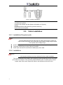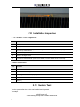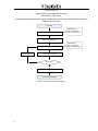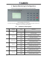
1
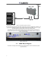
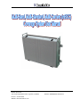
BRAVO TECH INC Add.: 6185 Phyllis Drive Unit D, Cypress, CA 90630 Phone: 1-714-230-8333 Website: www.bravotechinc.com Revision: UM·MBSC055-040·REV.A ©1999-2008 Bravo Tech Inc. All rights reserved. The “MBSC Coverage System” must be installed only in a restricted access area. The “MBSC Coverage System” is designed to operate according to the specification of this User Manual. Improper installation and operation of this equipment beyond the installation procedures, beyond the designed operating specifications, and not in compliance with regulatory requirements will revoke any warranty and may: Prevent the equipment from performing properly Violate regulatory RF emissions requirements Require removal of the equipment from service. I TABLE OF CONTENTS 1 2 INTRODUCTION ............................................................................................................................. 1 1.1 MBSC COMPONENTS ................................................................................................................. 1 1.2 MBSC CONNECTION ................................................................................................................... 1 1.3 MBSC BLOCK DIAGRAM .............................................................................................................. 2 1.4 OUTLINE DRAWING ..................................................................................................................... 4 SYSTEM INSTALLATION ............................................................................................................... 5 2.1 INSTALLATION FLOW ................................................................................................................... 5 2.2 INSTALLATION SITE ..................................................................................................................... 5 2.3 ANTI-CORROSION AND SHOCK-PROTECTION ................................................................................. 5 2.4 ILLUMINATION, VENTILATION AND FIRE PROTECTION ..................................................................... 5 2.5 POWER REQUIREMENTS ............................................................................................................. 6 2.6 LIGHTNING PROTECTING AND GROUNDING ................................................................................... 6 2.7 INSTALLATION PREPARATION ....................................................................................................... 6 2.8 MBSC UNITE INSTALLATION ........................................................................................................ 6 2.8.1 Installation Requirements ................................................................................................. 6 2.8.2 Installation......................................................................................................................... 6 2.9 CABLE INSTALLATION .................................................................................................................. 7 2.9.1 Installation Requirements ................................................................................................. 7 2.9.2 Installation......................................................................................................................... 7 2.10 INSTALLATION INSPECTION .......................................................................................................... 8 2.10.1 mBSC Unit Inspection ...................................................................................................... 8 Cable Inspection .............................................................................................................................. 8 2.11 3 4 II SYSTEM TEST ............................................................................................................................ 8 SYSTEM MONITORING & CONFIGURATION............................................................................. 10 3.1 INDICATORS DESCRIPTION......................................................................................................... 10 3.2 SYSTEM MONITORING & CONFIGURATION ...................................................................................11 3.2.1 Screen Menu ...................................................................................................................11 3.2.2 PA STATUS..................................................................................................................... 12 3.2.3 MS STATUS (System Status) ......................................................................................... 13 3.2.4 CONTROL (Power Amplifier Attenuation Setting and Restart) ...................................... 13 TERMS, ACRONYMS & ABBREVIATIONS ................................................................................. 15 LIST OF FIGURES FIGURE 1 MBSC UNIT 1 FIGURE 3 IN-LINE MBSC SYSTEM CONNECTION 2 FIGURE 3 MBSC PORTS 2 FIGURE 4 MBSC SCHEMATIC 3 FIGURE 5 MBSC OUTLINE DRAWING 4 FIGURE 6 INSTALLATION FLOW 5 FIGURE 7 INSTALLING INFLATABLE BOLT 7 FIGURE 8 INSTALLING GROUNDING CABLE 8 FIGURE 12 FLOW CHART OF SYSTEM DEBUGGING 9 FIGURE 15 MBSC LCD & KEY PANEL III 10 1 Introduction The Multi-band, Multi-Standard, Multi-Carrier(mBSC) High Power Coverage System is a feed-forward, in-line power amplifier operates in various mobile bands for indoor coverage and/or tunnel coverage. mBSC system provides complete “once-for-all” coverage solution for cellular communication system in any environment with multiple frequency bands, air interface independent, and multiple carriers. 1.1 mBSC Components The In-line mBSC is a multi-carrier linear power amplifier which includes MCPAs(Multi-carrier Power Amplifier), LNAs(Low Noise Amplifier), Duplexers, Control Unit, Power Supply Unit and Cooling Fans. Figure 1 mBSC Unit 1.2 mBSC Connection mBSC connects with BTS/POI (Point of Interface) and antenna, shown as below. 1 POI(Pont of Itnerface) Figure 2 In-line mBSC System Connection POI interfaces with signal side close to BTS, either direct connects to multiple BTS, repeaters. For downlink POI combines the signal up from multiple bands and feed to mBSC system. For uplink POI splits signal into multiple bands received from mBSC system. The mBSC system provides downlink signal booster and uplink sensitivity improvement for multiple bands signal, which may be in multiple standards and multiple carriers. The ports of mBSC are shown below. Figure 3 mBSC Ports 1.3 mBSC Block Diagram The mBSC Coverage System amplifies the downlink signals as well as increases the uplink signals sensitivity. 2 Figure 4 mBSC Schematic 3 1.4 Outline Drawing Figure 5 mBSC Outline Drawing 4 2 System Installation 2.1 Installation Flow Figure 6 Installation Flow 2.2 Installation Site The mBSC unit is installed on the wall. The wall should be water-resistant, dry, non-caustic and without high-voltage power leaking. The wall’s bearing capacity is more than 136kg. Concrete walls and brick walls are recommended, because those walls can fix expanded screws. Masonry walls or sandy-dust walls are not suitable. 2.3 Anti-corrosion and Shock-protection To safeguard products and operators, the installing location must be kept away from caustic or poisonous pollutants. If the site can’t meet seismic, it must be properly reinforced. 2.4 Illumination, Ventilation and Fire Protection The installation site should have enough illumination for installation and maintenance needs. Flammable and explosive material should not be near the site. 5 2.5 Power Requirements Nominal voltage: 220V AC. Variety range: 180-264 V AC, 47-63 Hz Single Phase. The power consumption of the mBSC Unit is about 1300W. Make sure to select a fuse or breaker with the proper capacity. A 10A or 15A breaker is recommended. 2.6 Lightning Protecting and Grounding The cross section of grounding cable should be no smaller than 25mm2. The grounding cable should be connected to earth ground directly without any splices. Keep the grounding cable as short as possible. 2.7 Installation Preparation The following technical files and tools will be used for a successful installation: A multimeter Phillips screwdrivers Flat blade screwdrivers Wrenches A Drill A VSWR testing device N adapters RF testing cables Power meter (part of hand-held tester) 2.8 mBSC Unite Installation 2.8.1 Installation Requirements Unused circuit breaker Convenient maintenance access Sufficient space for installation 2.8.2 Installation Caution: The following high-altitude operation should be only performed by qualified personnel under well protection. 6 Figure 7 Installing Inflatable Bolt Instructions: 1) Hold mount in place; 2) Make holes (Please find the distance information on Figure 5); 3) Drill; 4) Install expansion bolts (M10X70) (concrete anchors); 5) Bolt the mount into place. 2.9 Cable Installation 2.9.1 Installation Requirements Note: The NEC(National Electrical Code) does not allow signal wires to share the same conduit with power wires unless the signal cable’s voltage range is equal to the power wire’s voltage range. Avoid bundling signal cable and grounding cable/power cable, keep them separate. The power cable and grounding cable are supplied. Check open and short circuits before installing the power cable. 2.9.2 Installation Attention: All the power switches must be switched off before cable installation. The ground terminal of the mBSC unit is at the top of the housing near to the convection port as shown in Figure 8. The grounding cable should be green or yellow-green colored copper cable, with section larger than 25mm2 and resistance lower than 0.5Ω. 7 Figure 8 Installing Grounding Cable 2.10 Installation Inspection 2.10.1mBSC Unit Inspection Item Description 1 Stable and normal. 2 Properly fastened 3 Screws and nuts screwed tightly, without missing flat washers and spring washers. Spring washers must be on the top of flat washers. 4 No cable damage. 5 Clean, no smudges or dust. 6 Connections between metallic parts must be reliable, to assure reliable electric connectivity. Cable Inspection Item Description 1 The connection of the cable is tight, not loose or damaged. 2 The cable shell not damaged. 3 Grounding cable is connected properly. 4 Cables are dressed neatly, power kept separate from signal. 5 The minimum bending radius of the cable is proper. (Shouldn’t be less than twenty times of the cable’s diameter.) 2.11 System Test Test the system after the device was installed and inspected. Test steps: mBSC power off VSWR testing: sweep test of cables and antenna 8 mBSC power on Signal testing: indoor signal level testing Effect testing: CQT testing Coverage Optimize: based on the signal & effect testing result, adjust the mBSC parameters to optimize the coverage Test Start Test Data Before Installation OME Statistic CQT Test Statistic BTS Coverage Range Install and Adjust mBSC Test Data After Installation System Optimize No Compare The Test Data Best Effect? Yes Test Process End Document Management Figure 9 Flow Chart of System Debugging 9 OME Statistic CQT Test Statistic BTS Coverage Range 3 System Monitoring & Configuration There’s a LCD & Key Panel inside the remote unit as the figure below. Figure 10 mBSC LCD & Key Panel In the top of the panel, there’re 10 LED indicators. The key pad is in the right. And the LCD displayer is in the left below the indicators. 3.1 # Indicator 1 PWR 2 3 2 3 4 10 Indicators Description Status Description Green Power supply works normally Off No power supply Green IDEN uplink LNA works normally Red IDEN uplink LNA alarm Green IDEN downlink PA works normally Red IDEN downlink PA alarm Green GSM900 uplink LNA works normally Red GSM900 uplink LNA alarm Green GSM900 downlink PA works normally Red GSM900 downlink PA alarm Green GSM1800 uplink LNA works normally Red GSM1800 uplink LNA alarm IDEN UP IDEN DOWN GSM UP GSM DOWN PCS_UP 5 6 7 8 Green GSM1800 downlink PA works normally Red GSM1800 downlink PA alarm Green WCDMA uplink LNA works normally Red WCDMA uplink LNA alarm Green WCDMA downlink PA works normally Red WCDMA downlink PA alarm Green(Flashing) System works normally Red(Flashing) System alarm PCS_DOWN UMTS_UP UMTS_DOWN WORK Notes: The indicators are customized according to the actual mobile systems. 3.2 System Monitoring & Configuration The soft key pad contains 0~9 numbers and 6 function buttons. Following is the description for the operation. # Keys Function Description 1 0~9 Parameter setting and functional item choosing 2 UP Go to the previous page 3 DOWN Go to the next page 4 DEL Back to the main menu 5 ENTER Confirm 6 LEFT Go the left item 7 RIGHT Go to the right item 3.2.1 Screen Menu When the screen is in idle, the LCD will be off automatically. It will be on while any key is pressed and display the screen saver of “mBSC System”. Press any soft key again, it will display the main menu as below. 11 Menu Name Description PA STATUS Power Amplifier working status MS STATUS System status CONTROL Power Amplifier’s attenuation setting and restart 3.2.2 PA STATUS There’re 3 screens under ‘PA STATUS’ menu. Below is the menu description in detail. S creen Menu Item UP IDEN | UP GSM900 | UP PCS1800 | UP UMTS2100 | DW IDEN | DW GSM900 | DW PCS1800 | DW UMTS2100 Description Press soft key of ‘1-8’ or ‘LEFT, RIGHT’ to choose address of PA 1 Link: OK | ERR Communicate connection is OK or Error RFfor: **.* dBm Forward power RFin: **.* dBm Input power UP IDEN | UP GSM900 | UP PCS1800 | UP UMTS2100 | DW IDEN | DW GSM900 | DW PCS1800 | DW UMTS2100 Press soft key of ‘1-8’ or ‘LEFT, RIGHT’ to choose address of PA 2 VSWR: *.* VSWR value Temp: **.* °C PA temperature ATTE: **dB Attenuator value UP IDEN | UP GSM900 | UP PCS1800 | UP UMTS2100 | DW IDEN | DW GSM900 | DW PCS1800 | DW UMTS2100 3 Press soft key of ‘1-8’ or ‘LEFT, RIGHT’ to choose address of PA ALC: **.* dB Auto level Control value STATUS: RUN | STOP PA status ALARM: NO|OV_TMP | OV_POW | OV_DRV | VSWR PA alarm PA alarm parameters Description: 12 PA Alarm Item Parameters Description NO No alarm OV_TMP Over Temperature Alarm OV_POW Over Power Alarm OV_DRV Over Drive Alarm VSWR Over VSWR Alarm 3.2.3 MS STATUS (System Status) There’re 3 screens under ‘MS STATUS’ menu. Below is the menu description in detail. Screen Menu Item Description STATUS: OK | ALARM System Operation status Temp: **.* °C System temperature VOL: **.* V System input voltage Door: Open | Close Door status FAN1 STA: ** OK | ERR Fan1 rotating rate: circle/minute OK or Error FAN2 STA: ** OK | ERR Fan2 rotating rate: circle/minute OK or Error FAN3 STA: ** OK | ERR Fan3 rotating rate: circle/minute OK or Error FAN4 STA: ** OK | ERR Fan4 rotating rate: circle/minute OK or Error FAN5 STA: ** OK | ERR Fan5 rotating rate: circle/minute OK or Error FAN6 STA: ** OK | ERR Fan6 rotating rate: circle/minute OK or Error FAN7 STA: ** OK | ERR Fan7 rotating rate: circle/minute OK or Error 1 2 3 3.2.4 CONTROL (Power Amplifier Attenuation Setting and Restart) There’s only 1 screen under ‘CONTROL’ menu. Below is the menu description in detail. 13 S creen Menu Item UP IDEN | UP GSM900 | UP PCS1800 | UP UMTS2100 | DW IDEN | DW GSM900 | DW PCS1800 | DW UMTS2100 1 ATTE: ** dB 14 Description Press soft key of ‘1-8’ or ‘LEFT, RIGHT’ to choose address of PA Power amplifier attenuation setting, ajustable range 0~30dB, 1dB step Run Restart the power amplifier Return Back to main menu mBSC User Manual 4 Terms, Acronyms & Abbreviations 15 Terms/Acronyms/Abbreviation Definition ANT Antenna AWG American Wire Gauge BTS Base Transceiver Station or Base Transceiver System C° Degree Celsius COM Serial Communication Port CQT Call Quality Test dB Decibels dBm Power measurement referenced to the specific power level of one watt DIN Deutsches Insitut für Normung eV (German standards institution) 7-16 DIN German standards RF connector: 7mm OD of inner contact, 16mm ID of outer contact. DL Downlink EMC Electromagnetic Compatibility LNA Low Noise Amplifier MU mBSC Master Unit NMS Network & Monitoring System MCPA Multi-carrier Power Amplifier MHz Megahertz MTBF Mean Time Between Failures OMC-R Operation Monitor Center - Radio mBSC User Manual 16 PA Power Amplifier RF Radio Frequency RU mBSC Remote Unit RX Receive or Receiver TMA Tower Mounted Amplifier TX Transmit, Transmitter VSWR Voltage Standing Wave Ratio