1
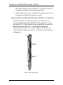
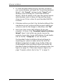
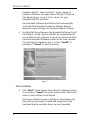
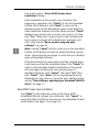
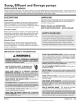
BarcoMed 5MP2FH for
Color Coronis 3MP
Installation & User Manual
B410513
July 2004
www.barco.com
BarcoMed 5MP2FH for
Color Coronis 3MP
Installation & User Manual
Copyright
This document is copyrighted. All rights are reserved. Nor this
document, nor any part of it, may be reproduced or copied in any
form or by any means - graphical, electronic, or mechanical
including photocopying, taping or information storage and
retrieval systems - without written permission of Barco
© 2004 Barco N.V. All rights reserved.
Notice
Although every attempt has been made to achieve technical
accuracy in this document, we assume no responsibility for errors
that may be found. Our goal is to provide you with the most
accurate and usable documentation possible; if you discover
errors, please let us know.
BarcoView software products are the property of BarcoView.
They are distributed under copyright by Barco N.V. or BarcoView,
LLC., for use only under the specific terms of a software license
agreement between Barco N.V. or BarcoView LLC. and the
licensee. No other use, duplication, or disclosure of a BarcoView
software product, in any form, is authorized.
The specifications of BarcoView products are subject to change
without notice.
Trademarks
All trademarks and registered trademarks are of their respective
companies.
FCC notice
This equipment has been tested and found to comply with the
limits of a class A digital device, pursuant to Part 15 of the FCC
rules. These limits are designed to provide reasonable protection
against harmful interference when the equipment is operated in
a commercial environment. This equipment generates, uses and
can radiate radio frequency energy and, if not installed and used
in accordance with the instruction manual, may cause harmful
2
BarcoMed 5MP2FH for Color Coronis 3MP
interference to radio communications. Operation of this
equipment in a residential area is likely to cause harmful
interference in which case the user will be required to correct the
interference at his own expense.
Disposal Information
The lamps inside the display contain mercury. Do not throw the
display in the trash. Dispose of it as required by local ordinances
or regulations.
BarcoMed 5MP2FH for Color Coronis 3MP
3
(This page intentionally left blank.)
4
BarcoMed 5MP2FH for Color Coronis 3MP
Table of Contents
Table of contents
Installation.................................................................................. 7
BarcoMed 5MP2FH Overview ............................................................. 9
Installing the BarcoMed 5MP2FH display controller........................ 11
Software installation ......................................................................... 15
Display Controller Tools ............................................................ 29
Barco Display Tab .............................................................................. 31
Introduction ................................................................................ 31
Using the Barco Display Tab ...................................................... 32
BarcoMed Driver Tab ......................................................................... 35
Introduction ................................................................................ 35
Using the BarcoMed Driver Tab................................................. 35
Status .......................................................................................... 36
Palette Mode .............................................................................. 37
Drawing Modes .......................................................................... 37
Monitor Configuration ................................................................ 37
BarcoMed Hardware Tab................................................................... 39
Introduction ................................................................................ 39
Using The BarcoMed Hardware Tab .......................................... 40
Display Utilities ......................................................................... 49
Barco DPMS Screen Saver ................................................................. 51
Introduction ................................................................................ 51
Barco DPMS Screen Saver Options ............................................ 52
Getting started with the Barco DPMS Screen Saver................. 54
Using the Barco DPMS Screen Saver ......................................... 55
Installing or Reinstalling Barco DPMS ....................................... 59
Barco I-Switch Software.................................................................... 63
Overview .................................................................................... 63
v
Table of Contents
Troubleshooting........................................................................ 65
Display resolution.............................................................................. 67
Setting the resolution of your Color Coronis 3MP display ....... 67
Driver re-installation, updates or removal....................................... 71
Reinstalling or updating your BarcoMed 5MP2FH driver......... 71
Uninstalling the BarcoMed 5MP2FH driver ............................... 72
vi
Installation
7
Installation
(This page intentionally left blank.)
8
BarcoMed 5MP2FH Overview
BarcoMed 5MP2FH Overview
The BarcoMed 5MP2FH Display Controller delivers a quality pixel
image with 24-bit True Color for medical imaging applications.
Minimum System Requirements
•
Pentium II 266 MHz with 256MB of system memory
(minimum) for optimum performance consult your
application provider for their recommended minimum
system memory requirements (Pentium 800MHz with 512
MB RAM for cineloops)
•
PCI 2.2 Compliant System
•
Windows® XP Service Pack 1 or Windows® 2000 Service
Pack 4
•
64-bit PCI slot with no obstructions (a 32-bit PCI slot may
also be used, but will result in decreased performance)
Features of theBarcoMed 5MP2FH
•
64-bit/66Mhz single slot, half-length PCI card
•
512 MB of Memory
•
Dual Head Configuration
•
1536 x 2048 resolution
•
High quality image with 24-bit true color
•
8-bit grayscale rendering for viewing grayscale images on
Coronis Color Displays
•
400MB/second image download speed
•
Real time window panning
•
Hardware cursor
•
Full Speed VGA Emulation
•
Display Properties Control Panel to dynamically change
display settings
9
BarcoMed 5MP2FH Overview
•
Control Panel support for the English (U.S.), Dutch, German,
Japanese, Korean, Simplified Chinese and Traditional Chinese
languages
Supported resolutions for each head of the BarcoMed 5MP2FH display
controller
•
1536 x 2048 @ 60Hz
•
2048 x 1536 @ 60Hz
The following resolution is also available on head 1 when the OS
is booted in VGA mode.
•
640x480 @ Default Refresh Rate, 16 colors
System Configuration Guidelines
Because of the low power consumption and low heat generation
of the BarcoMed 5MP2FH, multiple boards may be installed in
adjacent PCI slots or adjacent to other PCI boards. Additionally
there should be no need to modify either the PC’s power supply
and/or cooling system.
10
Installing the BarcoMed 5MP2FH display controller
Installing the BarcoMed 5MP2FH display controller
Caution: Wear a grounded, protective ESD strap during
installation or handling of the display controller. Electrostatic
charges can damage the display controller.
Prior to installing your BarcoMed 5MP2FH display controller(s) in
your PC please take a few minutes to familiarize yourself with
both the display controller and the PCI slots in your computer.
Figure 1: The BarcoMed 5MP2FH display controller
Jumper location
There is one user settable jumper on the BarcoMed 5MP2FH. It is used
to enable or disable the VGA capabilites of the display controller.
11
Installing the BarcoMed 5MP2FH display controller
Figure 2: VGA Jumper Enlarged View
Using the VGAcapabilities of the BarcoMed 5MP2FH
Prior to installing the BarcoMed 5MP2FH, decide if you are going
to use its on-board VGA capabilities. If you are, check the setting
of the Jumper at J-1 on the graphics board. (See VGA Jumper, J-1,
Figures 1 and 2) By default, VGA should be enabled, on the top
two pins.
NOTE: To use multiple BarcoMed 5MP2FH display controllers in a
single host with VGA enabled, you need to enable VGA on only
ONE of the BarcoMed 5MP2FH display controllers and disable VGA
on ALL other BarcoMed display controllers.
Examples of PCI slots
Although the BarcoMed 5MP2FH is a 64–bit board, it may be
installed in either a 64–bit or 32–bit PCI slot. However, installing
it in a 32–bit PCI slot will result in a decrease in performance.
Figure 3 illustrates the types of slots so that you can correctly
identify which one to use for the BarcoMed 5MP2FH.
12
Installing the BarcoMed 5MP2FH display controller
Figure 3: PCI and RAID Controller Slots
Install the BarcoMed 5MP2FH controller in your computer
following these steps:
1.
Turn off the power to your computer and disconnect the
power cord, however make sure that the computer chassis is
still grounded.
2.
Remove the chassis cover according to the manufacturer’s
instructions. Be sure to observe safety warnings.
3.
If you have decided to use the on-board VGA capabilities of
the BarcoMed 5MP2FH (see Using the VGAcapabilities of
the BarcoMed 5MP2FH on page 12), you must now
remove any VGA display controller(s) that are currently
installed in the computer.
4.
Install the BarcoMed 5MP2FH Controller into a free PCI slot,
either 32 bit or 64 bit (see figure 2, for examples of slots).
Be sure that the display controller is seated firmly in the slot.
5.
Secure the card to the chassis with the PC’s I/O panel
mounting screw, and replace the chassis cover.
6.
Connect the primary display (left most display in a linear
configuration, top most in a vertical configuration) to the
uppermost connector on the BarcoMed 5MP2FH (the output
farthest from the motherboard – “Head 1” in figure 4 on
page 14) using the provided DVI cable. For a dual-headed
13
Installing the BarcoMed 5MP2FH display controller
BarcoMed 5MP2FH setup, connect the secondary display to
the other connector on the display controller.
7.
Replace the chassis cover, reconnect the power cord, turn on
the power, and boot the system as usual.
Running multiple BarcoMed 5MP2FH display controllers in a single host
The physical order of the displays may vary when you are
running multiple BarcoMed 5MP2FH display controllers. This is
due to the PC’s PCI bus control in the system BIOS, and not the
BarcoMed display controller. It may become necessary,
depending on how your PC’s BIOS configures the PCI bus, to
switch your DVI display connections to achieve a linear desktop
configuration.
Figure 4: The Video Outputs.
14
Software installation
Software installation
Tip: These instructions apply to both Windows® 2000 and
Windows® XP.
Preparation
Prior to installing your Color Coronis 3MP software the following
should be done.
1.
Install the BarcoMed 5MP2FH display controller(s) in your
system.
2.
Connect the Color Coronis 3MP display panel(s) to the
BarcoMed 5MP2FH display controller(s) and power supply(s).
3.
Decide if you want to install the Barco DPMS Screen Saver
and the Barco I-Switch Software in addition to the driver.
(See “Barco DPMS Screen Saver” on page 51 and “Barco ISwitch Software” on page 63 for descriptions of these addon features.)
4.
Decide if you are going to install the BarcoMed 5MP2FH
driver with DualView enabled or disabled (See Step “7.” on
page 19 for a description of DualView).
5.
Decide if you want to enable the DirectDraw capabilities of
the BarcoMed 5MP2FH display controller. If you are
uncertain, use the default setting as this setting can be
changed latter using the BarcoMed Driver Tab of the
Windows Display Properties control panel.
Using the BarcoMed product installation wizard
To install your BarcoMed 5MP2FH Windows display controller
driver Software for the first time follow the steps below.
If you are reinstalling the drivers or installing a new driver
release over an existing driver release skip to the step 5:
1.
Boot your system, and log in using an account with
administrator privileges.
15
Software installation
2.
For each BarcoMed 5MP2FH display controller installed in
your system Windows will launch the “Found New Hardware
Wizard”. Click “Cancel”. Continue to click “Cancel” until
Windows stops launching the “Found New Hardware
Wizard”. Please be patient as this may take several minutes
while Windows scans its library of Plug-and-Play device
drivers to see if it has a driver for your BarcoMed 5MP2FH
controller.
3.
If Windows advises you that it has finished installing all the
new devices in your system and that you must reboot your
system in order for the changes to take effect, click “No”.
4.
Insert your Color Coronis 3MP Software CD into your
computer’s CD drive. If the “BarcoMed Product Installation
Wizard” doesn’t start within one minute, browse the
contents of your Color Coronis 3MP Software CD and double
click on the file: “Setup.exe” to start the wizard.
The BarcoMed Product Installation Wizard will begin by
inspecting your system to make certain that all of the
Windows components it needs are up to date. If they are,
the BarcoMed Product Installation Wizard will display the
BarcoMed Product Installation Wizard’s welcome screen (see
figure 5 on page 17). If the screen shown in figure 5 on
page 17 appears, please skip to step “5.” on page 18.
16
Software installation
Figure 5
If it determines that the Microsoft Installer is either out of
date or missing, it will display the screen shown in figure 6
below. Click “OK” to continue, the wizard will then install a
newer version of the Microsoft Installer.
Figure 6
The BarcoMed Product Installation Wizard will advise you
when it has successfully installed the new version of the
Microsoft Installer. Click “OK”.
The Wizard may prompt you to restart your system. If it
does, click “Yes” to restart your system now.
When your system restarts log in using an account with
administrator privileges. Windows will again launch the
“Found New Hardware Wizard” for each BarcoMed 5MP2FH
it finds in your system. Click “Cancel”. Continue to click
“Cancel” until Windows stops launching the “Found New
17
Software installation
Hardware Wizard - Video Controller”. Again, please be
patient as Windows will again scan its library of Plug-andPlay device drivers to see if it has a driver for your
BarcoMed 5MP2FH controller.
The BarcoMed Software Install Wizard will automatically
restart and the BarcoMed Product Installation Wizard’s
welcome screen will again be displayed (figure 7 below).
5.
By default all the software on the BarcoMed Software CD will
be selected. For the initial installation we recommend that
you install all of the software. If you do not want to install a
particular BarcoMed Software product at this time, deselect
it by clearing the checkbox next to it. Click “Install” to
continue or “Cancel” to exit the wizard.
Figure 7
Driver installation
6.
Click “Next” on the Display Driver Wizard’s Welcome Screen
to continue or “Cancel” to exit the Display Driver Wizard and
return to the Software Install Wizard.
The Device Selection Screen’s dialog box should show only
those devices physically installed and supported by the
BarcoMed display controller driver on your BarcoMed
18
Software installation
Software CD. Select the device you want to install and then
click “Next”.
Note: If there are no BarcoMed devices installed, or if
Windows does not recognize the installed devices, or if the
driver on your BarcoMed Software CD does not support the
installed devices, the dialog box will be empty1, and the
BarcoMed driver wizard will exit when you click “Finish” or
“Cancel”.
Caution: You can install the driver for only one type of
BarcoMed device at a time. If you have multiple types of
BarcoMed devices installed in your computer, you will need
to rerun the installer to install the drivers for the other
devices.
If you select a device with an installed driver, the wizard will
warn you if the installed driver is newer than the one you
are installing (figure 8 below).
Figure 8
Click “OK” to install the new driver. If you don’t want to
replace the exiting driver, click “OK” and then click
“Cancel”.
7.
Your selection on the "Enable DualView" screen (figure 9 on
page 20) determines if DualView is enabled or not. DualView
allows a dual head display controller to display two separate
desktops, one for each display instead of a single virtual
desktop that spans across both displays.
1. If Windows does not recognize the installed BarcoMed device, special settings
may need to be made in the BIOS to support non-AGP video controllers or to
support multiple video controllers. Check with your PC manufacturer.
19
Software installation
Figure 9
The difference between running with DualView enabled or
disabled is shown in figure 10 below and figure 11 on
page 21. If you wish to enable DualView “check” the
checkbox next to "Enable the DualView device?", and click
"Next". If you do not wish to enable DualView “clear” the
checkbox next to "Enable the DualView device?", and click
"Next" to continue.
Figure 10: DualView Disabled–Rectangle 2 represents the combined
heads of the BarcoMed Controller.
20
Software installation
Figure 11: DualView Enabled–Rectangles 2 & 3 represents the
individual heads of the BarcoMed Controller.
Special Note: If you installed the drivers with DualView
disabled, Windows will still show two devices installed for
each BarcoMed Display Controller installed under "Display
Adapters" in the "Device Manager Control Panel". The second
device will be disabled. This is normal. Do NOT try to enable
any of the disabled display adapters.
8.
The “Device Confirmation” screen displays the device driver
that will be installed and if DualView will be enabled or not.
If you want to change your selection, click “Back” to return
to the Device Selection Screen. Click “Next” to begin
installing the driver. Click “Cancel” to abort the driver
installation.
Caution: Once you click “Next”, you cannot cancel the
driver installation.
Prior to beginning the installation the BarcoMed Driver Install
Wizard will warn you that while the driver is being installed
your display may flicker. Click “OK” to continue.
21
Software installation
9.
When the screen shown in figures 12 or 13 below appears,
click “Yes” or “Continue Anyway” to continue. This screen
may appear multiple times.
Figure 12: Windows 2000 Digital Signature Not Found Warning
Figure 13: Windows XP Windows Logo Testing Warning
When the Driver Install Wizard tells you that it has
successfully installed the selected driver, click “Finish”.
The wizard will now begin installing the next selected piece
of BarcoMed Software. If you are working with the default
selections, this will be the Barco DPMS Screen Saver. Please
22
Software installation
turn to the section, “Barco DPMS Screen Saver
installation” below.
If the installation of the products you selected at the
beginning is complete, click “Finish” to exit the BarcoMed
Product Install Wizard or click “Back” to return to the
Welcome Screen of the BarcoMed Product Install Wizard to
select additional software to install. When you click “Finish”
Windows may prompt you to restart your system, if it does
click “Yes”. When your system restarts, boot normally and
log in using an account with administrator privileges and
turn to the section “Barco monitor plug and play
software” on page 26.
Note: Clicking “Cancel” will also return you to the BarcoMed
Product Install Wizard, but will not delete the Barco display
driver. The wizard will also begin to install the next selected
piece of BarcoMed Software.
If the Wizard failed to successfully install the selected driver,
it will warn you that the installation failed. Click “Finish” to
return to the BarcoMed Product Install Wizard. The wizard
will now begin installing the next selected piece of
BarcoMed Software. Click “Cancel”, then click “Yes” then
click “Finish”. Now “Back” and try reinstalling the driver
following the steps above or using the steps outlined in the
section “Reinstalling or updating your BarcoMed 5MP2FH
driver” on page 71.
Barco DPMS Screen Saver installation
Click “Next” on the Welcome Screen of the Barco DPMS
InstallShield Wizard to begin the installation. Click “Cancel” to
cancel the DPMS installation and return to the BarcoMed Product
Install Wizard (see figure 14 on page 24).
23
Software installation
Figure 14
10. The “Customer Information” screen will appear. The Installer
will automatically fill in the blanks using the information
entered when Windows was installed on your system. You
may change this information if you wish. Click “Next” to
continue.
11. The “Setup Type” page will now appear. Choose “Typical” to
install the default schemes with English names. Choose
“Custom” to install the default schemes with either Dutch or
German names. Currently the default schemes are not
supported in the Japanese, Korean and Chinese languages.
We recommend that the users of these three languages
install the English default schemes and then rename and
save them into their language in the DPMS configuration
screen. Click “Next” to continue.
12. The “Ready to Install Program” page will now appear, click
“Install” to install DPMS or “Back” if you wish to change
any of your DPMS installation settings.
During installation the wizard will display a progress screen.
13. When the Windows Installer has finished installing DPMS,
the “InstallShield Wizard Completed” page will appear, click
24
Software installation
“Finish” to exit the Barco DPMS InstallShield Wizard and
return to the BarcoMed Product Install Wizard Welcome
Screen.
After returning to the BarcoMed Product Install Wizard Welcome
Screen, the wizard will clear the checkbox next to DPMS Screen
Saver and will automatically launch the Barco I-Switch Software
Install Wizard if the Barco I-Switch Software was selected when
you began installing the software.
If the installation of the products you selected at the beginning is
complete, click “Finish” to exit the BarcoMed Product Install
Wizard or click “Back” to return to the Welcome Screen of the
BarcoMed Product Install Wizard to select additional software to
install. When you click “Finish” Windows may prompt you to
restart your system, if it does click “Yes”.
When your system restarts, boot normally and log in using an
account with administrator privileges and turn to the section
“Barco monitor plug and play software” on page 26.
Barco I-Switch software installation
Note: The Barco I-Switch Software is only available for systems
which have the Portrait Accelerator in the Display Panel and
BarcoMed Display Driver releases that include the Barco I-Switch
Software. The Barco I-Switch Software may not be available for
your system.
14. Click “Next” on the Welcome Screen of the Barco I-Switch
Software InstallShield Wizard to continue the installation.
Click “Cancel” to cancel the Barco I-Switch Software
installation and return to the BarcoMed Product Install
Wizard.
15. The Barco I-Switch Software must be installed on a local hard
drive in order for it to function correctly. We recommend that
you install it in the default location: C:\WINNT. If you wish to
install the Barco I-Switch Software in a different location use
the “browse” button on the Install Location Screen of the
25
Software installation
Barco I-Switch Software InstallShield Wizard. Click “Next” to
continue the installation.
16. Click “Next” on the “Setup has enough information” screen
to continue.
17. When the Barco I-Switch Software InstallShield Wizard has
finished installing the software, it will tell you that it has
finished installing the software on your computer and
prompt you to click “Finish” to complete the setup. Click
“Finish” to exit the Barco I-Switch Software InstallShield
Wizard and to return to the BarcoMed Product Installation
Wizard.
When your system restarts, boot normally and log in using an
account with administrator privileges and set the resolution of
your Color Coronis 3MP displays.
Barco monitor plug and play software
After your system restarts and you have logged in, Windows will
install the Barco Monitor Plug-n-Play software. If Windows
displays the screens shown in figure 15 below and figure 16 on
page 27, click “Yes” or “Continue Anyway” to continue.
Figure 15: Windows 2000 Digital Signature Not Found Warning
26
Software installation
Figure 16: Windows XP Windows Logo Testing Warning
The Barco Monitor Plug and Play software will automatically set
the resolution for the displays of your Color Coronis 3MP System.
However, the second head of a dual headed system may be
inactive. To make this display active you must extend your
desktop to this display using the “Windows Display Control
Panel”. If for some reason Windows failed to correctly set the
resolution of your panels please turn to the section “Setting the
resolution of your BarcoMed Nio display” on page 5 of the
Troubleshooting Section of this manual for instructions on
setting the resolution.
27
Software installation
(This page intentionally left blank.)
28
Display Controller Tools
29
Display Controller Tools
(This page intentionally left blank.)
30
Barco Display Tab
Barco Display Tab
Introduction
The Barco Display Tab is used for gathering information about the
BarcoMed Flat Panel Display(s).
To access the Barco Display Tab do the following:
1.
Open the “Display Properties Control Panel” by right clicking
on the desktop, then select “Properties”.
2.
Under Windows 2000 and Windows XP, click on the
“Settings” tab. Double click on the rectangle that
represents the BarcoMed Display you are working with to
bring up its properties page. Click on the “BARCO Display”
tab (figure 17).
Figure 17: BARCO Display Tab under Windows 2000 and
Windows XP
31
Barco Display Tab
Using the Barco Display Tab
Displays
All of the available display adapters that are of the same type as
the current barco display adapter are shown here graphically,
with one display icon representing each port of a display
adapter. The icon orientation reflects the display resolution. Only
those ports with a display attached to them are active. If an icon
is grayed out, that indicates a port with no head attached to it.
When running DualView under Windows 2000 and Windows XP
the desktop must be extended to include each display, otherwise
those ports will not be visible to the Barco Display Tab.
Hovering the cursor over a display icon will pop up a window
with information that identifies the display.
Properties
You may access the Properties page of the currently selected
display, which is represented by the monitor icon above with the
black frame around it, by either clicking on the “Properties”
button or double clicking on the icon.
BarcoMFD library
This is the version of the barcomfd library currently used. This
library provides APIs for interacting with the displays.
CORONIS Display Properties
You may access the Properties page of the currently selected
display, which is represented by the monitor icon above with the
black frame around it, by either clicking on the “Properties”
button or double clicking on the icon. This screen (figure 18 on
page 33) shows properties of the currently active display.
Name: Displays the model name of the display.
Serial Number: Displays the serial number of the display.
32
Barco Display Tab
Backlight RunTime: This is time in hours that the back light has
been on. A common question is: How much longer will the
backlight last? The backlight will typically last a very long time,
but will only be able to hold a calibrated output of 130 cd/m2 for
17000 hours, after which time it will become slowly dimmer. For
displays calibrated at 130 cd/m2, an estimate of how long it will
be before a backlight replacement is needed = 17000 hours –
backlight age.
Firmware Revisions: This is the runtime firmware that is loaded
in the display. This information may be helpful when there is a
problem.
Internal Temperature: This is the temperature inside the
display. It starts out at about the ambient temperature when the
display backlight is first turned on, then rises slowly to a steadystate temperature as the display warms up. Changes in light
level due to temperature variations are completely controlled by
the I-Guard sensor on the front of the display.
Current Luminance Value: This is the current luminance value of
the display. It may vary a bit from time to time, for the display
continuously calibrates itself to meet the target luminance value.
Figure 18
33
Barco Display Tab
(This page intentionally left blank.)
34
BarcoMed Driver Tab
BarcoMed Driver Tab
Introduction
After the BarcoMed Windows display controller driver is installed,
a new Display Properties tab is available for configuring special
features of the BarcoMed display controller.
Languages supported
The BarcoMed Driver Tab supports the following languages:
English (U.S) (default)
Dutch
German
Korean
Japanese
Simplified Chinese
Traditional Chinese
To change between the languages select the correct region via
the Regional Settings Control Panel in your machine’s Start >
Settings > Control Panel.
Using the BarcoMed Driver Tab
Please note that you must have logged on to Windows using an
account with administrator privileges in order to use the
BarcoMed Tabs of the Windows Display Control Panel to change
any display settings.
1.
Open the “Display Properties Control Panel” by right clicking
on the desktop, then select “Properties”.
2.
Under Windows 2000 or Windows XP, click on “Settings”
tab. Double click on the rectangle that represents the Barco
display whose settings you wish to change to bring up its
property page. Click on the “BarcoMed Driver” tab (see
figure 19 on page 36).
35
BarcoMed Driver Tab
Figure 19: BarcoMed Driver Tab under Windows 2000 and
Windows XP
Status
The Status section displays information about the current
BarcoMed display controller, driver, and the currently selected
display resolution.
Graphics Board
This displays the current BarcoMed display controller.
Driver Version
This displays the current BarcoMed driver version.
36
BarcoMed Driver Tab
Resolution
This displays the currently selected display resolution.
Palette Mode
If any of the options in this section are grayed out, then they are
not available for the model controller with which you are
working.
Drawing Modes
In the Drawing Mode section you can choose from the following
Drawing Modes. If any of the options in this section are grayed
out, then they are not available for the model controller with
which you are working.
Enable DirectDraw
This option allows the user to enable or disable DirectDraw.
DirectDraw is a software interface that provides direct access to
display devices while maintaining compatibility with the
Windows graphics device interface (GDI). DirectDraw provides a
device-independent way for applications to gain access to the
hardware features of specific display devices. If you enable
DirectDraw, your application will have the choice of using
DirectDraw or GDI. If you disable DirectDraw, your application will
use GDI instead of DirectDraw. Please note that in any case, your
application can always use BarcoMed driver functions (i.e.
WinBarco) or other graphics extensions (such as OpenGL).
Monitor Configuration
If the options in this section are grayed out, then they are not
available for the model controller with which you are working.
Under Windows 2000 and Windows XP you can enable or
disable DualView through the drop-down menu.
37
BarcoMed Driver Tab
In SingleView mode the Monitor Configuration section allows you
to select the number of monitors that the current display boards
should drive, as well as how the monitors should be positioned.
For example, if the current board installation is capable of
driving four heads, but you only have three monitors which are
placed in a single row, then you can select the “Three monitors–
one row” option from the pull-down list. This would cause the
Windows virtual desktop to be resized to fit on the three
monitors, and you can move your cursor horizontally from one
screen to the other. If “Custom Configuration” is displayed, it
means that the current monitor configuration was set via the
registry and it doesn’t agree with any of the configurations that
the display control panel supports. Contact Barco Medical
Imaging Systems for further information.
38
BarcoMed Hardware Tab
BarcoMed Hardware Tab
Introduction
The BarcoMed Hardware Tab is used for gathering information
about BarcoMed display controller(s). For all BarcoMed display
controller(s) it will display PCI information. For BarcoMed display
controller(s) based on the AURA video chipset it will also display
information about the Firmware installed on the board.
Table 1:
AURA
Controllers
Non-AURA
Controllers
BarcoMed
Hardware Tab
Support
Nio
PCI and Firmware
Information
1MP2FH
PCI and Firmware
Information
2MP1
PCI Information Only
2MP1NT
PCI Information Only
2MP2
PCI Information Only
PCI and Firmware
Information
2MP2H
2MP2CF–3D
PC and Firmware
Information
2MP2CP
PCI and Firmware
Information
2MP2FH
PCI and Firmware
Information
3MP2FH
PCI and Firmware
Information
5MP1H
PCI Information Only
39
BarcoMed Hardware Tab
Table 1:
AURA
Controllers
Non-AURA
Controllers
BarcoMed
Hardware Tab
Support
PCI and Firmware
Information
5MP1HM
5MP2
PCI Information Only
5MP2 AURA
PCI and Firmware
Information
5MP2F
PCI and Firmware
Information
5MP2FH
PCI and Firmware
Information
Using The BarcoMed Hardware Tab
To access the BarcoMed Hardware Tab do the following:
40
1.
Open the “Display Properties Control Panel” by right clicking
on the desktop, then select “Properties”.
2.
Click on the “Settings” tab. Double click on the rectangle
that represents one of the heads of the BarcoMed Display
Controller you are working with to bring up its properties
page. Click on the “BarcoMed Hardware Tab” (see
figure 20 on page 41).
BarcoMed Hardware Tab
Figure 20 BarcoMed Hardware Tab under Windows 2000 or
Windows XP
Device
Displays the current BarcoMed display controller, driver, and the
currently selected display resolution.
Identify Device: This button is for BarcoView Medical Imaging
Systems (MIS) internal use only and is grayed out.
PCI Information
Device ID: Displays the device’s PCI Device ID number.
Vendor ID: Displays the device manufacturer’s PCI Vendor ID
number.
41
BarcoMed Hardware Tab
Subsystem ID: Displays the device’s PCI Subsystem ID number.
SubsystemVendorID: Displays the device’s PCI Subsystem
Vendor ID number.
VGA Status: Displays whether the VGA capabilities of the
BarcoMed controller are enabled or disabled.
Firmware Information
Product Name: Displays the name of the BarcoMed display
controller installed in the selected PCI slot.
Serial Number: Displays the serial number of the BarcoMed
display controller installed in the selected PCI slot.
VGA Bios Version: Displays the VGA Bios version for the
BarcoMed display controller installed in the selected PCI slot.
Firmware Version: Displays the firmware version for the
BarcoMed display controller installed in the selected PCI slot.
Hardware Version: Displays the Hardware Version for the
BarcoMed display controller installed in the selected PCI slot.
“Advanced ...” Button: By clicking on this button, the user can
display more information about the BarcoMed display controller
installed in the selected PCI slot.
Utilities
“Generate Report” Button:
Clicking this button will launch the BarcoMed Self Exam utility.
BarcoMed Self Exam is an automated Barco Diagnostic Tool that
is used to gather the information that support engineers and
technicians need to help determine the root cause of a customer
problem. It probes the system for various types of system
information, and saves it to a web-page report that can then be
analyzed by the Barco ImageCare team.
BarcoMed Self Exam is implemented in a Wizard Format. The
BarcoMed Self Exam Wizard will first ask the user to provide
42
BarcoMed Hardware Tab
detailed customer contact information. After completion of the
customer contact information screen, the Wizard will then ask
the user to provide a description of the problem, and prompt the
user to enter the Medical Viewing Applications that they are
using. The Wizard will then automatically collect the diagnostic
information from the user’s system. When completed, the Wizard
will alert the user of completion and open the report. The report
is saved in an HTML format file on the user’s desktop.
Welcome Screen
The Welcome screen reminds the user to close all applications
before starting the wizard. The screens that follow guide the user
through gathering pertinent diagnostic data that will help in
determining the root of the problem.
Customer Information Screen
All fields on this screen must be filled in. This screen asks the
user for contact information that will help the Barco support
team contact the customer. The user will not be allowed to move
forward to the next screen unless all of the fields are filled in.
Customer Diagnostic Questions Screen
This screen allows the user to tell the Barco ImageCare team as
much as possible about the problem. For the Medical Viewing
Applications Running field, enter the medical applications that
are currently running on the system with the problem. For the
“Any Applications using DIMPL” question, select the “radio
button” that applies to the correct response. For the “Detailed
Description” field, enter a detailed description of the problem.
And, for the Additional Notes field, enter any information that
could help the Barco ImageCare team diagnose the problem.
Gathering Diagnostic Data Screen
Important: When performing the Graphics Operations, you must
drag the "Gathering Diagnostic Data Screen" onto the display
for which you want the Graphics Operations data.
43
BarcoMed Hardware Tab
This screen gathers the diagnostic data from the user’s system as
described above in this document. Click the ”Start Diagnostic”
button to begin the diagnostic gathering process.
To perform the graphics operations test, check the graphics
operations checkbox. During the graphics operations test, several
things will happen to the screen. Each graphics operation is
performed for 10 seconds. To quit the graphics operations test at
any time, press the Escape button.
To create a summary report for QA purposes, check the summary
report checkbox. If this box is checked, an additional report will
be saved on the desktop called BarcoExamSummary.txt.
Please let the wizard gather all of the data, the “NEXT” button
will be enabled only after all of the information is gathered. Once
the information is gathered, the user may not go back in the
wizard screens.
Completion Screen
The BarcoMed Self Exam has collected all of the information. A
report called BarcoSelfExam.html exists on the desktop with all
of the diagnostic data that was collected. If a summary report
was created, it exists on the desktop called
BarcoExamSummary.txt.
Submitting the Data to Barco Support
Once BarcoMed Self Exam has collected the data, the user can
submit it to ImageCare, Barco Medical Imaging Systems’
customer support organization by email. To do this you need a
system with access to the World Wide Web.
44
1.
Enter the following address in your Web browser’s address
bar: http://www.barco.com/medical/
2.
In the left hand column click on “Contact us”
3.
Then click on “Support” in the drop down menu.
4.
Find the appropriate ImageCare Center for your country and
click on the email link.
BarcoMed Hardware Tab
5.
Enter a subject and a brief message describing the
problem about which you are requesting help.
6.
Attach the BarcoMed Self Exam report(s) to the email
message and send it.
You will receive an acknowledgment of receipt of your email by
the end of the next business day.
45
BarcoMed Hardware Tab
Update Device... Button:
Clicking this button will launch the BarcoMed Hardware
Configuration utility. This program allows the user to flash update
the firmware stored in the ROM of the currently selected
BarcoMed display controller. The BarcoMed Hardware
46
BarcoMed Hardware Tab
Configuration utility is implemented in a Wizard format, which
guides the user through the flash update procedure. The user will
be prompted to select a firmware update file to use for the
update process. This file will be provided by BarcoView MIS if and
when a firmware update is required.
47
BarcoMed Hardware Tab
(This page intentionally left blank.)
48
Display Utilities
49
Display Utilities
(This page intentionally left blank.)
50
Barco DPMS Screen Saver
Barco DPMS Screen Saver
Introduction
The Barco DPMS (Display Power Management Signaling) Screen
Saver allows the user to set power and display saving features
for medical displays controlled by BarcoMed display controllers.
At the end of the work day, the display will enter certain DPMS
states as requested by the display controller.
Note: The Barco DPMS Screen Saver will not control any displays
connected to a non-Barco display controller.
The default state for the Barco DPMS Screen Saver is the Off
state. In addition to simply entering the Off state after the work
day, the user can specify that the display first go through two
other DPMS Screen Saver states before going into Off state.
These two other states for the Screen Saver are Stand-By and
Suspend. The user can specify how much time should be spent in
each state in the “Amount of Time in each DPMS Power State”
section.
On Barco CORONIS displays, the I-GUARD will stabilize the image
within a few seconds after the display returns to the active state,
thus eliminating the need for a warm-up period at the beginning
of the work day.
On Liquid Crystal Display (LCD) based displays, such as the Barco
CORONIS displays, it is not necessary to invoke a screen saver as
there is no CRT phosphor to preserve. However, one can extend
the life of the backlight in the LCD display, in addition to realizing
great power savings, during period of user inactivity by using
DPMS to quickly enter the Off state. We recommend setting the
work day to be as short as possible to get the maximum power
savings on CORONIS displays.
The Barco DPMS Screen Saver can also be used when no one is
logged on.
51
Barco DPMS Screen Saver
Barco DPMS Screen Saver Options
From the “Barco DPMS Screen Saver Control Panel” you can
change many DPMS screen saver elements simultaneously. The
DPMS screen saver elements in each scheme are work schedule,
work day screen saver, DPMS settings after work day, and many
additional options.
Current Scheme
Lists the three “DEFAULT” schemes which you can use as they
are. Or you can modify them to meet your office’s schedule.
Save As
Saves your current Barco DPMS Screen Saver settings. The name
you specify will appear in the Scheme list so you can easily
restore these settings later.
Delete
Deletes the scheme that is selected in the Scheme box.
Work Schedule
In this part of the control panel the user may specify the “Begin
Work Day” and “End Work Day” times for each work day. If the
system is not expected to be used, leave both the “Begin Work
Day” and the “End Work Day” times as the same time.
Begin Work Day
The “Begin Work Day” time is the time after which the system is
expected to start being used. During the work day, the screen
saver selected by the user in the “Screen Saver During Work Day”
section is used during user inactivity.
End Work Day
The “End Work Day” time is the time after which the system is
not expected to be used any more for that day. After the work
52
Barco DPMS Screen Saver
day, the display is set to one of the DPMS states (Stand-By,
Suspend, or Off) by the display controller during user inactivity.
Screen Saver During Work Day
On LCD based displays, such as the Barco CORONIS displays, it is
not necessary to invoke a screen saver as there is no CRT
phosphor to preserve. However, one can extend the life of the
backlight in the LCD display, in addition to realizing great power
savings, during period of user inactivity by quickly entering the
Off state. We recommend setting the work day to be as short as
possible to get the maximum power savings on CORONIS displays.
Available Savers
Lists the Available Screen Savers.
Settings
Changes settings for the selected screen saver.
DPMS Settings After Work Day
If you have an display controller that supports DPMS calls, then
you will be able to set the DPMS Settings for after the work day.
Otherwise, a text box will be displayed telling you why DPMS
functions are not available.
Amount of Time in each DPMS State
After the work day, the display will be placed into one of the
following DPMS Power States: Stand-By, Suspend, or Off. The
default setting is for the display to directly go into the Off State
and spend no time in the Stand-By or Suspend states. If the user
wishes to go into the Stand-By or Suspend states before going
53
Barco DPMS Screen Saver
into the Off state, select the required amount of time for each
state.
If requested, the display will first go into Stand-By state, then
into Suspend state, and then into Off state. The properties of
DPMS states are listed in the following table:
Table 2:
DPMS State
Monitor Recovery
Time
Power Savings
On
None
N/A
Stand-by
Minimal
Short
Suspend
Substantial
Longer
Off
Maximum
Longest
Monitor Settings
If you have a Barco Medical Display, select “Barco Quick Start.” If
a non-Barco display is being used, select the amount of time it
takes your display to warm up via the “Monitor Setting” section.
Contact your display vendor for this warm-up time.
On Barco CORONIS displays, the I-GUARD will stabilize the image
within a few seconds after the display returns to the active state
so there is no need for a warm-up time period.
Use As Logon Screen Saver
Check the box to use the Barco DPMS Screen Saver when no one
is logged into the system.
Uncheck the box to use the default screen saver when no one is
logged into the system.
Getting started with the Barco DPMS Screen Saver
The easiest way to get started is to select an existing settings
scheme and then modify it with your preferences. Settings
54
Barco DPMS Screen Saver
schemes are separated into two kinds, DEFAULT (global) and
PRIVATE (personal).
Upon installation, three default settings schemes are installed
and no private settings schemes are installed.
Default settings schemes are visible to all users of the system.
However, they can be modified only by users with administrator
privileges. If a user who does not have administrator privileges
tries to save a scheme using an existing default scheme name,
an error message is displayed saying “you must have
administrator rights to modify a default scheme.” If an
administrator saves a scheme using an existing default scheme
name, a message is displayed to tell the user that the
modification is saved to a default scheme and will be visible to
all users. If the administrator saves a scheme using a new name,
then the user is asked if the scheme should be saved as a default
scheme or a private scheme. Since there is no distinction
between how a default scheme and a private scheme is
displayed, it is highly recommended that the user uses a
different naming convention to distinguish the two (i.e. use
“DEFAULT: ...” for default schemes).
Private schemes are personal. They are not shared and are
visible only to the users who created them. All users of a system,
including those who do not have administrator privileges, can
create, modify or delete private schemes. When the delete
button is pressed, the user is asked to confirm the delete
request.
Using the Barco DPMS Screen Saver
Using the Barco DPMS Screen Saver is similar to using any other
Windows Screen Saver, each user of the system must select the
Barco DPMS Screen Saver so that Windows will store the
selection in the user’s profile. If a user does not select the Barco
55
Barco DPMS Screen Saver
DPMS Screen Saver as his screen saver, the next time he logs on
to the system the screen saver selection may be blank.
After selecting the Barco DPMS Screen Saver the user must then
select a settings scheme for the Screen Saver to follow. To set up
the Barco DPMS Screen Saver using one of the three default
schemes, please do the following:
1.
Open the “Display Properties Control Panel” by right clicking
on an empty space of the desktop and selecting
“Properties” from the drop down menu; then select the
“Screen Saver” tab (see figure 21 below and figure
figure 22 on page 57).
1.
Select the “Barco DPMS Screen Saver” in the “Screen
Saver” drop down menu if it is not already selected.
Figure 21: Windows 2000 Screen Saver Tab
56
Barco DPMS Screen Saver
Figure 22: Windows XP Screen Saver Tab
2.
Click on the “Settings” button. The “Barco DPMS Screen
Saver Control Panel” will open (see figure 23 below).
Figure 23: Barco DPMS Settings Control Panel
57
Barco DPMS Screen Saver
3.
Use the default schemes by selecting one of the three
default schemes. Click “OK”. Then Click “OK” again.
Note: If you make any changes to any of the settings of one
of the three default schemes, the Current Scheme field will
blank and you MUST SAVE your changes by clicking on the
“Save As ...” button. When you click on the “Save As ...”
button, the name of the last scheme you used will be
automatically displayed, you can then choose to use that
scheme name or enter a new name. If you enter a name
other than one of the three default scheme names, the
program will ask you if you wish to save the scheme as a
DEFAULT scheme (figure 24 below). Click “Yes” to save the
settings scheme as a DEFAULT scheme, click “No” to save
the scheme as a PRIVATE scheme. After you have saved the
scheme, then click OK and the new scheme will be in effect.
Figure 24
To create a new scheme by modifying one of the three default
schemes please do the following.
58
1.
Open the “Display Properties Control Panel” by right clicking
on an empty space of the desktop and selecting
“Properties” from the drop down menu; then select the
“Screen Saver” tab.
2.
Select the “Barco DPMS Screen Saver” in the “Screen
Saver” drop down menu if it is not already selected.
3.
Click on the “Settings” button. The “Barco DPMS Screen
Saver Control Panel” will open.
Barco DPMS Screen Saver
4.
Select one of the default schemes from the “Current
Scheme” drop down menu.
5.
Set the Work Schedule by setting the beginning and ending
time of your work day for each day of the week.
6.
Select the screen saver you wish to use during the work day
in the “Screen Saver During Work Day” section.
7.
Select the amount of time you wish to spend in the Stand-By
and Suspend states after the work day has ended. Please
note that after the time specified has elapsed when you are
in Stand-By or Suspend, you will automatically go into the
Off state.
8.
Select the amount of time it takes for your display to warm
up. If you have a Barco Medical Display, select “Barco Quick
Start”. If you are using a non-Barco display, select the
amount of time it takes your display to warm up via the
“Monitor Setting” section. Contact your display vendor for
this warm-up time. On Barco CORONIS displays, the I-GUARD
will stabilize the image within a few seconds after the
display returns to the active state, thus eliminating the need
for a warm-up period at the beginning of the work day.
9.
If you wish to use this DPMS screen saver as the screen saver
at logon time, check the “Use As Logon Screen Saver” box
in the “Additional Options” section.
10. Save your preferences by pressing the “Save As” button and
entering a new profile name in the “Save Profile Setting”
dialog box.
11. Apply your new scheme by clicking “OK”.
12. Click “OK” again to close the “Display Properties Control
Panel”.
Installing or Reinstalling Barco DPMS
To install or reinstall the Barco DPMS Screen Saver insert the
CORONIS Software CD in the appropriate device on your computer
59
Barco DPMS Screen Saver
and run the BarcoMed Product Install Wizard (please see the
section Software Installation for complete instructions).
Special Note: Reinstalling the Barco DPMS Screen Saver will over
write the DPMS configuration settings and you will need to
reconfigure the DPMS settings on your system.
Uninstalling Barco DPMS
To remove the Barco DPMS Screen Saver from your system insert
the Color Coronis 3MP Software CD in the appropriate device on
your computer, run the BarcoMed Product Install Wizard and
follow these steps.
1.
Select only the DPMS Screen Saver on the BarcoMed Product
Install Wizard’s welcome screen and click “Install”.
2.
Click “Next” on the Welcome Screen of the Barco DPMS
InstallShield® Wizard to begin the installation.
3.
Select the radio button next to “Remove” on the Program
Maintenance screen of the Wizard and click “Next”.
4.
Click “Remove” on the Remove Program Screen of the
Wizard (figure 25 below).
Figure 25
60
Barco DPMS Screen Saver
5.
When the Wizard has finished removing the program, click
“Finish” on the InstallShield Wizard Completed Screen of the
Wizard.
6.
Click “Quit” to exit the BarcoMed Product Installation
Wizard.
61
Barco DPMS Screen Saver
(This page intentionally left blank.)
62
Barco I-Switch Software
Barco I-Switch Software
Overview
Note: The Barco I-Switch Software is only available for systems
which have the Portrait Accelerator in the Barco Display Panel
and BarcoMed Display Driver releases that include the Barco ISwitch Software. The Barco I-Switch Software may not be
available for your system.
The Barco I-Switch Software is designed to detect changes in the
physical orientation of the rotatable Barco flat-panel display(s)
and to change the resolution of the display to match the physical
orientation of the display. The Barco I-Switch Software will
support up to eight Barco flat-panel displays on four BarcoMed
Display Controllers. The Barco I-Switch Software supports
Windows 2000 and Windows XP.
The Barco I-Switch Software is designed to react only to changes
in physical orientation of the Barco flat-panel displays, not to
changes in screen resolution effected from the Windows Display
Control Panel. The Barco I-Switch Software functions only after
the Barco Windows Display Controller Drivers have been
installed, the resolution set using the Windows Display Control
Panel and the Barco I-Switch Software has been installed.
Barco I-Switch Software has a limited user interface available
through an icon in the system status tray. The system tray icon is
just a toggle to put the service to sleep. During this sleeping
phase, the Service will continue to track changes in the physical
orientation. The service will use these saved settings to set the
appropriate state model on startup.
Windows 2000 and Windows XP
Although Windows 2000 and Windows XP support multiple types
of display controllers, they support only one resolution per
display controller. Rotating a single head on any given BarcoMed
Display Controller will affect both of the heads connected to that
display controller. If you change the physical orientation of one
63
Barco I-Switch Software
Barco display connected to any given BarcoMed Display
Controller, the Barco I-Switch Software will change the resolution
for both of the Barco displays connected to that BarcoMed
Display Controller and you will need to change the physical
orientation of the second display to match the orientation of the
first display.
Installation or Reinstallation
To install or reinstall the Barco I-Switch Software insert the
BarcoMed Software CD in the appropriate device on your
computer and run the BarcoMed Software Install Wizard and
select only the Barco I-Switch Software (please see the section
Software Installation for complete instructions).
Removal of Barco I-Switch Software
To remove the Barco I-Switch Software from your system use the
Windows “Add/Remove Programs” utility found in the
Windows Control Panel.
Or you may remove the Barco I-Switch Software from your
system by doing the following:
64
1.
Click on the Windows “Start” button.
2.
Click on “Run".
3.
Type the following text in the dialog box: "cmd".
4.
Click on "OK".
5.
Type the following text in the command line window:
“coronisrotationservice /uninstall”
6.
When the program has finished, closed the command line
window.
Troubleshooting
65
Troubleshooting
(This page intentionally left blank.)
66
Display resolution
Display resolution
Setting the resolution of your Color Coronis 3MP display
In order to set the resolution of your Color Coronis 3MP display
you must be logged in using an account with administrator
privileges.
1.
To set the resolution of your Color Coronis 3MP display(s)
right click on the desktop and select “Properties”.
2.
Select the “Settings” tab.
3.
Select the rectangle that represents the first Color Coronis
3MP display attached to the BarcoMed 5MP2FH display
controller you are working with.
NOTE: If you are using the VGA capabilities of your
BarcoMed 5MP2FH display controller, the resolution for the
first display may be set to a VGA resolution of “640 x 480”
pixels with 16 colors and a default refresh rate. If your
BarcoMed 5MP2FH controller is not running VGA, the display
may not be enabled yet. To enable the display, check the
“Extend my Windows desktop onto this monitor” checkbox,
but do NOT click the “Apply” button at this time.
If you installed your BarcoMed 5MP2FH drivers in SingleView
mode (default for Windows 2000) there will be one
rectangle for the virtual display representing the two heads
controlled by each BarcoMed 5MP2FH display controller.
If you installed your BarcoMed 5MP2FH drivers in DualView
mode (default for Windows XP) there will be a rectangle
representing each head controlled by each
BarcoMed 5MP2FH display controller. This will be true even if
you have only one display connected to your
BarcoMed 5MP2FH controller. Both displays of a display
controller cannot be enabled at the same time unless their
display properties match. If necessary detach the second
display of the BarcoMed 5MP2FH display controller you are
working with by right clicking on the rectangle that
67
Display resolution
represents it, deselect “Attached” and click the “Apply”
button.
Tip: Since Windows 2000 and Windows XP will not let you
detach the primary display connected to a particular
controller, you may need to temporarily make another
display the primary display
Caution: if you have a single display configuration and you
have enabled DualView, Windows will not allow you to
attach the second head. This is normal and not a bug.
4.
For the display which is still attached click on the
“Advanced” Button.
5.
Select the “Adapter” tab and then click on the “List All
Modes” button. Select the resolution and refresh rate that
your Color Coronis 3MP display supports from the dialog box
and click “OK”.
Tip: In the Adapter box, the Adapter string shows if this
display is the First View or the Second View attached to the
display controller. Please make a note of this, so that you
can arrange the displays in the correct order later if
necessary.
6.
Click “OK” on the bottom of the Adapter Control Panel. If the
“OK” button on the bottom of the Adapter Control Panel is
not visible, press the “TAB” key once and then press
“CTRL”+“Enter” to select “OK”.
7.
Click “OK” in the “Windows will now apply your new
desktop settings” dialog box. Your Color Coronis 3MP display
should now synchronize and display the Windows desktop.
8.
Click “Yes” when asked, “Your desktop has been
reconfigured. Do you want to keep these settings?”
To set the resolution of the second display attached to the
BarcoMed display controller you are working with, go back to the
“Settings” tab of the “Display Properties Control Panel”. Attach
68
Display resolution
the display you detached in step 2 above, by right clicking on the
rectangle that represents it and selecting “Attached”.
Now repeat steps 5-8 above for this display.
If you are using a Quad-Head Configuration repeat all of the
above steps for the two displays on the second display controller.
Tip: After installing DualView and setting the resolutions in a
Quad-Head Configuration you may need to drag the heads into
the proper position in the window on the “Settings” tab, so that
the arrangement in the window on the “Settings” tab matches
the physical arrangement of your configuration.
Figure 26: The Windows Display Properties Control Panel Settings
Tab after the drivers have been installed and the resolution set
with DualView Enabled.
Note: The system shown in figure 26 above is a dual-head,
single BarcoMed 5MP2FH display controller, with a 3rd party VGA
controller configuration. Your system may look different.
69
Display resolution
(This page intentionally left blank.)
70
Driver re-installation, updates or removal
Driver re-installation, updates or removal
Reinstalling or updating your BarcoMed 5MP2FH driver
Caution: If you previously uninstalled the driver, do not allow
Windows’ Plug and Play software to reinstall the driver for you.
To reinstall or update only the BarcoMed 5MP2FH driver, follow
the steps described in the section “Using the BarcoMed Product
Installation Wizard” with the following changes.
1.
Boot your system, and log in using an account with
administrator privileges.
2.
Insert your Color Coronis 3MP Software CD into your
computer’s CD drive. If the “BarcoMed Product Installation
Wizard” doesn’t start within one minute, browse the
contents of your Color Coronis 3MP Software CD and double
click on the file: “Setup.exe” to start the wizard.
The wizard will begin by displaying the screen shown in
figure 27 below.
Figure 27
3.
To update the driver, clear the checkbox next to “DPMS
Screen Saver” and “I-Switch” (figure 28 on page 72) and
click “Install”.
71
Driver re-installation, updates or removal
Figure 28
4.
Please turn to Step 6 on page 18 in the section titled “Driver
Installation” and follow the instructions to finish reinstalling
or updating your BarcoMed 5MP2FH driver.
When the driver has finished installing, click “Finish”. Then click
“Finish” again.
Reboot the system when prompted and then reset the resolution
of your displays if necessary.
Uninstalling the BarcoMed 5MP2FH driver
To remove the BarcoMed 5MP2FH display controller driver from
your system you must be logged in using an account with
administrator privileges.
Uninstalling the BarcoMed 5MP2FH driver
72
1.
Insert your BarcoMed 5MP2FH Software CD into your
computer’s CD drive. If the “BarcoMed Product Installation
Wizard” doesn’t start within one minute, browse the
contents of your Color Coronis 3MP Software CD and double
click on the file: “Setup.exe” to start the wizard.
2.
The BarcoMed Product Installation Wizard will display its
welcome screen.
Driver re-installation, updates or removal
3.
Make certain that the checkbox next to the driver is checked
and that all other checkboxes are unchecked (figure 29
below). Click “Install” to continue.
Figure 29
4.
Click “Next”.
5.
On the next screen (figure 30), check the checkbox next to
“Uninstall this device” and click “Next” to continue.
Figure 30
73
Driver re-installation, updates or removal
6.
Click “Next”.
7.
If you installed your driver with DualView enabled, skip to
step 8.
If you installed your driver with DualView disabled, click
“Next” to continue. Then click “Finish” to complete the
uninstall process. Click “Finish” again to exit the wizard.
Click “Yes” if Windows tells you that “you must restart your
computer before the new setting will take effect”.
8.
If you have installed your driver in DualView mode the
wizard will warn you that you must first disable DualView by
rebooting and then run the uninstall program again.
Figure 31
Click “OK” to continue.
9.
Click “Reboot” to disable DualView, click “Finish” to exit
the wizard and then click “Yes” to reboot your system.
10. When your system restarts, log in again using an account
with administrator priveleges. DualView should now be
disabled.
11. The “BarcoMed Product Installation Wizard” should
automatically restart. Finish uninstalling the driver by
clicking “Next” three times. Then click “Reboot”, “Finish”
and “Yes”.
If the “BarcoMed Product Installation Wizard” doesn’t
automatically restart, finish uninstalling the driver by
restarting the “BarcoMed Product Installation Wizard” by
browsing the contents of your Color Coronis 3MP Software
CD and double clicking on the file: “Setup.exe”. Then follow
Steps 3 through 7 on page 4 and page 6 to finish uninstalling
the driver.
74
(This page intentionally left blank.)
75
B410513
July 2004
www.barco.com