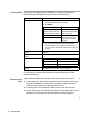
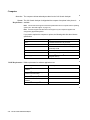
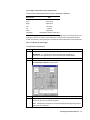
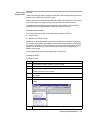
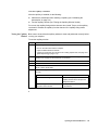
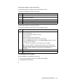
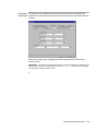
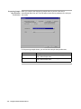
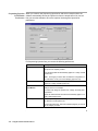
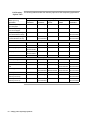
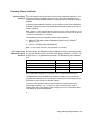
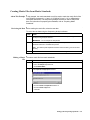
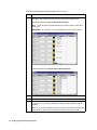
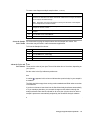
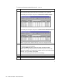
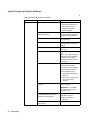
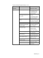
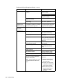
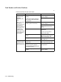
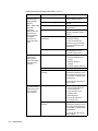
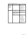
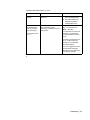
Download DRAFTJune

Transcript
DRAFT
June 21, 2001 10:06 am
Liane, 310UG_NT_Title.fm
ABI PRISM® 310 Genetic Analyzer
User Guide
© Copyright 2001,2010 Applied Biosystems
All rights reserved
For Research Use Only. Not for use in diagnostic procedures.
Information in this document is subject to change without notice. Applied Biosystems assumes no responsibility for any errors that may appear in this document. This
document is believed to be complete and accurate at the time of publication. In no event shall Applied Biosystems be liable for incidental, special, multiple, or
consequential damages in connection with or arising from the use of this document.
This instrument, Serial No. ____________________, is Authorized for use in DNA sequencing and fragment analysis. This authorization is included in the purchase
price of this instrument and corresponds to the up-front fee component of a license under process claims of U.S. patents and under all process claims for DNA
sequence and fragment analysis of U.S. patents now or hereafter owned or licensable by Applied Biosystems for which an Authorization is required, and under
corresponding process claims in foreign counterparts of the foregoing for which an Authorization is required. The running royalty component of licenses may be
purchased from Applied Biosystems or obtained by using Authorized reagents purchased from Authorized suppliers in accordance with the label rights accompanying
such reagents. Purchase of this instrument does not itself convey to the purchaser a complete license or right to perform the above processes. This instrument is also
licensed under U.S. patents and apparatus and system claims in foreign counterparts thereof. No rights are granted expressly, by implication or by estoppel under
composition claims or under other process or system claims owned or licensable by Applied Biosystems. For more information regarding licenses, please contact the
Director of Licensing at Applied Biosystems, 850 Lincoln Centre Drive, Foster City, California 94404.
ABI PRISM and the ABI PRISM design, AMPFLSTR, Applied Biosystems, GeneMapper, GeneScan, Genotyper, MicroAmp, PROCISE, QuantiBlot, SeqScape,
Sequence Navigator, and StockMarks are registered trademarks of Applied Biosystems or its subsidiaries in the U.S. and certain other countries.
ABI, AFPL, BigDye, CATALYST, FAM, GeneAssist, HEX, Hi-Di, JOE, LIZ, NED, PET, POP-4, POP-6, ROX, TAMRA, TET, and VIC are trademarks of Applied
Biosystems or its subsidiaries in the U.S. and certain other countries.
AmpliTaq, AmpliTaq Gold, GeneAmp and TaqMan are registered trademarks of Roche Molecular Systems, Inc.
All other trademarks are the sole property of their respective owners.
Applied Biosystems is committed to providing the world’s leading technology and information for life scientists.
Printed in the USA, 06/2010
Part Number 4317588 Rev. B
Contents
1 About This Guide
Introduction . . . . . . . . . . . . . . . . . . . . . . . . . . . . . . . . . . . . . . . . . . . . . . . . . . . . . . . . . . . . . . . . 1-1
In This Chapter . . . . . . . . . . . . . . . . . . . . . . . . . . . . . . . . . . . . . . . . . . . . . . . . . . . . . . . . 1-1
About This Guide . . . . . . . . . . . . . . . . . . . . . . . . . . . . . . . . . . . . . . . . . . . . . . . . . . . . . . . . . . . . 1-2
Overview of Contents . . . . . . . . . . . . . . . . . . . . . . . . . . . . . . . . . . . . . . . . . . . . . . . . . . . 1-2
About the Quick Reference Card. . . . . . . . . . . . . . . . . . . . . . . . . . . . . . . . . . . . . . . . . . . 1-3
Related Documents . . . . . . . . . . . . . . . . . . . . . . . . . . . . . . . . . . . . . . . . . . . . . . . . . . . . . 1-3
Safety . . . . . . . . . . . . . . . . . . . . . . . . . . . . . . . . . . . . . . . . . . . . . . . . . . . . . . . . . . . . . . . . . . . . . 1-4
Documentation User Attention Words . . . . . . . . . . . . . . . . . . . . . . . . . . . . . . . . . . . . . . . 1-4
Chemical Hazard Warning. . . . . . . . . . . . . . . . . . . . . . . . . . . . . . . . . . . . . . . . . . . . . . . . 1-4
Chemical Waste Hazard Warning . . . . . . . . . . . . . . . . . . . . . . . . . . . . . . . . . . . . . . . . . . 1-5
Site Preparation and Safety Guide. . . . . . . . . . . . . . . . . . . . . . . . . . . . . . . . . . . . . . . . . . 1-5
About MSDSs . . . . . . . . . . . . . . . . . . . . . . . . . . . . . . . . . . . . . . . . . . . . . . . . . . . . . . . . . 1-5
Ordering MSDSs . . . . . . . . . . . . . . . . . . . . . . . . . . . . . . . . . . . . . . . . . . . . . . . . . . . . . . . 1-6
Instrument Safety Labels . . . . . . . . . . . . . . . . . . . . . . . . . . . . . . . . . . . . . . . . . . . . . . . . . 1-6
About Waste Profiles . . . . . . . . . . . . . . . . . . . . . . . . . . . . . . . . . . . . . . . . . . . . . . . . . . . . 1-7
About Waste Disposal . . . . . . . . . . . . . . . . . . . . . . . . . . . . . . . . . . . . . . . . . . . . . . . . . . . 1-7
Before Operating the Instrument . . . . . . . . . . . . . . . . . . . . . . . . . . . . . . . . . . . . . . . . . . . 1-7
Safe and Efficient Computer Use. . . . . . . . . . . . . . . . . . . . . . . . . . . . . . . . . . . . . . . . . . . 1-7
Technical Support . . . . . . . . . . . . . . . . . . . . . . . . . . . . . . . . . . . . . . . . . . . . . . . . . . . . . . . . . . . . 1-9
Contacting Technical Support . . . . . . . . . . . . . . . . . . . . . . . . . . . . . . . . . . . . . . . . . . . . . 1-9
To Contact Technical Support by E-Mail . . . . . . . . . . . . . . . . . . . . . . . . . . . . . . . . . . . . 1-9
To Contact Technical Support by Telephone or Fax (North America) . . . . . . . . . . . . . . 1-9
To Contact Technical Support by Telephone or Fax (Outside North America). . . . . . . 1-11
To Reach Technical Support Through the Applied Biosystems Web Site . . . . . . . . . . . 1-12
To Obtain Technical Documents . . . . . . . . . . . . . . . . . . . . . . . . . . . . . . . . . . . . . . . . . . 1-12
To Obtain Customer Training Information . . . . . . . . . . . . . . . . . . . . . . . . . . . . . . . . . . 1-13
2 Overview of the 310 Genetic Analyzer
Introduction . . . . . . . . . . . . . . . . . . . . . . . . . . . . . . . . . . . . . . . . . . . . . . . . . . . . . . . . . . . . . . . . 2-1
In This Chapter . . . . . . . . . . . . . . . . . . . . . . . . . . . . . . . . . . . . . . . . . . . . . . . . . . . . . . . . 2-1
About This Chapter . . . . . . . . . . . . . . . . . . . . . . . . . . . . . . . . . . . . . . . . . . . . . . . . . . . . . 2-2
For More Information . . . . . . . . . . . . . . . . . . . . . . . . . . . . . . . . . . . . . . . . . . . . . . . . . . . 2-2
Section: Description of the Instrument . . . . . . . . . . . . . . . . . . . . . . . . . . . . . . . . . . . 2-3
In This Section . . . . . . . . . . . . . . . . . . . . . . . . . . . . . . . . . . . . . . . . . . . . . . . . . . . . . . . . . 2-3
Front of the Instrument. . . . . . . . . . . . . . . . . . . . . . . . . . . . . . . . . . . . . . . . . . . . . . . . . . . . . . . . 2-4
Diagram . . . . . . . . . . . . . . . . . . . . . . . . . . . . . . . . . . . . . . . . . . . . . . . . . . . . . . . . . . . . . . 2-4
iii
Doors. . . . . . . . . . . . . . . . . . . . . . . . . . . . . . . . . . . . . . . . . . . . . . . . . . . . . . . . . . . . . . . . 2-4
Status Indicators . . . . . . . . . . . . . . . . . . . . . . . . . . . . . . . . . . . . . . . . . . . . . . . . . . . . . . . 2-4
Back of the Instrument. . . . . . . . . . . . . . . . . . . . . . . . . . . . . . . . . . . . . . . . . . . . . . . . . . . . . . . . 2-5
Diagram. . . . . . . . . . . . . . . . . . . . . . . . . . . . . . . . . . . . . . . . . . . . . . . . . . . . . . . . . . . . . . 2-5
Service LEDs . . . . . . . . . . . . . . . . . . . . . . . . . . . . . . . . . . . . . . . . . . . . . . . . . . . . . . . . . 2-5
Serial Connections . . . . . . . . . . . . . . . . . . . . . . . . . . . . . . . . . . . . . . . . . . . . . . . . . . . . . 2-6
Reset Button . . . . . . . . . . . . . . . . . . . . . . . . . . . . . . . . . . . . . . . . . . . . . . . . . . . . . . . . . . 2-6
On/Off Switch . . . . . . . . . . . . . . . . . . . . . . . . . . . . . . . . . . . . . . . . . . . . . . . . . . . . . . . . . 2-6
Power Cord Receptacle. . . . . . . . . . . . . . . . . . . . . . . . . . . . . . . . . . . . . . . . . . . . . . . . . . 2-6
Behind the Doors of the Instrument. . . . . . . . . . . . . . . . . . . . . . . . . . . . . . . . . . . . . . . . . . . . . . 2-7
Overview. . . . . . . . . . . . . . . . . . . . . . . . . . . . . . . . . . . . . . . . . . . . . . . . . . . . . . . . . . . . . 2-7
Diagram. . . . . . . . . . . . . . . . . . . . . . . . . . . . . . . . . . . . . . . . . . . . . . . . . . . . . . . . . . . . . . 2-7
Gel Block Region . . . . . . . . . . . . . . . . . . . . . . . . . . . . . . . . . . . . . . . . . . . . . . . . . . . . . . 2-8
Detection Region . . . . . . . . . . . . . . . . . . . . . . . . . . . . . . . . . . . . . . . . . . . . . . . . . . . . . 2-10
Autosampler Region . . . . . . . . . . . . . . . . . . . . . . . . . . . . . . . . . . . . . . . . . . . . . . . . . . . 2-11
Section: Description of the Computer and Software . . . . . . . . . . . . . . . . . . . . . . . 2-13
In This Section . . . . . . . . . . . . . . . . . . . . . . . . . . . . . . . . . . . . . . . . . . . . . . . . . . . . . . . 2-13
Computer . . . . . . . . . . . . . . . . . . . . . . . . . . . . . . . . . . . . . . . . . . . . . . . . . . . . . . . . . . . . . . . . . 2-14
Overview. . . . . . . . . . . . . . . . . . . . . . . . . . . . . . . . . . . . . . . . . . . . . . . . . . . . . . . . . . . . 2-14
System Requirements . . . . . . . . . . . . . . . . . . . . . . . . . . . . . . . . . . . . . . . . . . . . . . . . . .
RAM Requirements . . . . . . . . . . . . . . . . . . . . . . . . . . . . . . . . . . . . . . . . . . . . . . . . . . .
Software . . . . . . . . . . . . . . . . . . . . . . . . . . . . . . . . . . . . . . . . . . . . . . . . . . . . . . . . . . . . . . . . . .
Overview. . . . . . . . . . . . . . . . . . . . . . . . . . . . . . . . . . . . . . . . . . . . . . . . . . . . . . . . . . . .
Software for Data Collection . . . . . . . . . . . . . . . . . . . . . . . . . . . . . . . . . . . . . . . . . . . .
Software for Data Analysis . . . . . . . . . . . . . . . . . . . . . . . . . . . . . . . . . . . . . . . . . . . . . .
Other Software . . . . . . . . . . . . . . . . . . . . . . . . . . . . . . . . . . . . . . . . . . . . . . . . . . . . . . .
2-14
2-14
2-15
2-15
2-15
2-16
2-16
Section: Theory of Operation . . . . . . . . . . . . . . . . . . . . . . . . . . . . . . . . . . . . . . . . . 2-17
In This Section . . . . . . . . . . . . . . . . . . . . . . . . . . . . . . . . . . . . . . . . . . . . . . . . . . . . . . .
What the 310 Genetic Analyzer Does . . . . . . . . . . . . . . . . . . . . . . . . . . . . . . . . . . . . . . . . . . .
DNA Sequencing . . . . . . . . . . . . . . . . . . . . . . . . . . . . . . . . . . . . . . . . . . . . . . . . . . . . .
Fragment Analysis . . . . . . . . . . . . . . . . . . . . . . . . . . . . . . . . . . . . . . . . . . . . . . . . . . . .
Principles of Operation . . . . . . . . . . . . . . . . . . . . . . . . . . . . . . . . . . . . . . . . . . . . . . . . . . . . . .
Sample Labeling . . . . . . . . . . . . . . . . . . . . . . . . . . . . . . . . . . . . . . . . . . . . . . . . . . . . . .
Automated Sample Handling . . . . . . . . . . . . . . . . . . . . . . . . . . . . . . . . . . . . . . . . . . . .
Electrokinetic Sample Injection . . . . . . . . . . . . . . . . . . . . . . . . . . . . . . . . . . . . . . . . . .
Electrophoresis . . . . . . . . . . . . . . . . . . . . . . . . . . . . . . . . . . . . . . . . . . . . . . . . . . . . . . .
Sample Fluorescence . . . . . . . . . . . . . . . . . . . . . . . . . . . . . . . . . . . . . . . . . . . . . . . . . .
Detection . . . . . . . . . . . . . . . . . . . . . . . . . . . . . . . . . . . . . . . . . . . . . . . . . . . . . . . . . . . .
Data Collection . . . . . . . . . . . . . . . . . . . . . . . . . . . . . . . . . . . . . . . . . . . . . . . . . . . . . . .
Virtual Filters and Dye Sets . . . . . . . . . . . . . . . . . . . . . . . . . . . . . . . . . . . . . . . . . . . . .
Matrix Files. . . . . . . . . . . . . . . . . . . . . . . . . . . . . . . . . . . . . . . . . . . . . . . . . . . . . . . . . .
Compatibility of Dyes and Virtual Filters. . . . . . . . . . . . . . . . . . . . . . . . . . . . . . . . . . .
Color Display of Data . . . . . . . . . . . . . . . . . . . . . . . . . . . . . . . . . . . . . . . . . . . . . . . . . .
iv
2-17
2-18
2-18
2-18
2-19
2-19
2-19
2-19
2-19
2-19
2-20
2-20
2-20
2-20
2-20
2-21
Virtual Filters and Associated Applications. . . . . . . . . . . . . . . . . . . . . . . . . . . . . . . . . . 2-21
Color Guide for DNA Sequencing Applications . . . . . . . . . . . . . . . . . . . . . . . . . . . . . . 2-21
Color Guide for Fragment Analysis Applications . . . . . . . . . . . . . . . . . . . . . . . . . . . . . 2-22
3 Operating the Instrument Hardware
Introduction . . . . . . . . . . . . . . . . . . . . . . . . . . . . . . . . . . . . . . . . . . . . . . . . . . . . . . . . . . . . . . . . 3-1
In This Chapter . . . . . . . . . . . . . . . . . . . . . . . . . . . . . . . . . . . . . . . . . . . . . . . . . . . . . . . . 3-1
Preparing the 310 Genetic Analyzer for a Run. . . . . . . . . . . . . . . . . . . . . . . . . . . . . . . . . . . . . . 3-2
Summary of Procedures. . . . . . . . . . . . . . . . . . . . . . . . . . . . . . . . . . . . . . . . . . . . . . . . . . 3-2
What to Do Next . . . . . . . . . . . . . . . . . . . . . . . . . . . . . . . . . . . . . . . . . . . . . . . . . . . . . . . 3-2
Section: Procedures for Setting Up and Maintaining the Instrument . . . . . . . . . . . 3-3
In This Section . . . . . . . . . . . . . . . . . . . . . . . . . . . . . . . . . . . . . . . . . . . . . . . . . . . . . . . . . 3-3
Autosampler . . . . . . . . . . . . . . . . . . . . . . . . . . . . . . . . . . . . . . . . . . . . . . . . . . . . . . . . . . . . . . . . 3-4
Cleaning the Autosampler . . . . . . . . . . . . . . . . . . . . . . . . . . . . . . . . . . . . . . . . . . . . . . . . 3-4
Calibrating the Autosampler . . . . . . . . . . . . . . . . . . . . . . . . . . . . . . . . . . . . . . . . . . . . . . 3-4
Homing the Autosampler. . . . . . . . . . . . . . . . . . . . . . . . . . . . . . . . . . . . . . . . . . . . . . . . . 3-6
Filling the Buffer Reservoir . . . . . . . . . . . . . . . . . . . . . . . . . . . . . . . . . . . . . . . . . . . . . . . 3-8
Loading the Samples . . . . . . . . . . . . . . . . . . . . . . . . . . . . . . . . . . . . . . . . . . . . . . . . . . . . 3-9
Buffers and Polymer. . . . . . . . . . . . . . . . . . . . . . . . . . . . . . . . . . . . . . . . . . . . . . . . . . . . . . . . . 3-10
When to Replace Reagents . . . . . . . . . . . . . . . . . . . . . . . . . . . . . . . . . . . . . . . . . . . . . . 3-10
Preparing the Polymer and the Electrophoresis Buffer . . . . . . . . . . . . . . . . . . . . . . . . . 3-10
Making Buffer for a Single Run . . . . . . . . . . . . . . . . . . . . . . . . . . . . . . . . . . . . . . . . . . 3-10
Storing the Buffer . . . . . . . . . . . . . . . . . . . . . . . . . . . . . . . . . . . . . . . . . . . . . . . . . . . . . 3-10
Checking for Polymer Leaks . . . . . . . . . . . . . . . . . . . . . . . . . . . . . . . . . . . . . . . . . . . . . 3-11
Capillary . . . . . . . . . . . . . . . . . . . . . . . . . . . . . . . . . . . . . . . . . . . . . . . . . . . . . . . . . . . . . . . . . . 3-14
About the Capillary . . . . . . . . . . . . . . . . . . . . . . . . . . . . . . . . . . . . . . . . . . . . . . . . . . . . 3-14
Cutting the Capillary . . . . . . . . . . . . . . . . . . . . . . . . . . . . . . . . . . . . . . . . . . . . . . . . . . . 3-14
Cleaning the Capillary Window. . . . . . . . . . . . . . . . . . . . . . . . . . . . . . . . . . . . . . . . . . . 3-14
Installing the Capillary . . . . . . . . . . . . . . . . . . . . . . . . . . . . . . . . . . . . . . . . . . . . . . . . . 3-15
Testing the Capillary Window . . . . . . . . . . . . . . . . . . . . . . . . . . . . . . . . . . . . . . . . . . . . 3-19
Removing and Storing the Capillary . . . . . . . . . . . . . . . . . . . . . . . . . . . . . . . . . . . . . . . 3-20
Verifying that the Capillary Fills Correctly . . . . . . . . . . . . . . . . . . . . . . . . . . . . . . . . . . 3-22
Avoiding Capillary Clogs . . . . . . . . . . . . . . . . . . . . . . . . . . . . . . . . . . . . . . . . . . . . . . . 3-22
Electrode. . . . . . . . . . . . . . . . . . . . . . . . . . . . . . . . . . . . . . . . . . . . . . . . . . . . . . . . . . . . . . . . . . 3-23
Overview . . . . . . . . . . . . . . . . . . . . . . . . . . . . . . . . . . . . . . . . . . . . . . . . . . . . . . . . . . . . 3-23
Cleaning the Electrode. . . . . . . . . . . . . . . . . . . . . . . . . . . . . . . . . . . . . . . . . . . . . . . . . . 3-23
Installing the Electrode . . . . . . . . . . . . . . . . . . . . . . . . . . . . . . . . . . . . . . . . . . . . . . . . . 3-24
Trimming the Electrode . . . . . . . . . . . . . . . . . . . . . . . . . . . . . . . . . . . . . . . . . . . . . . . . . 3-25
Straightening the Electrode . . . . . . . . . . . . . . . . . . . . . . . . . . . . . . . . . . . . . . . . . . . . . . 3-26
Gel Block . . . . . . . . . . . . . . . . . . . . . . . . . . . . . . . . . . . . . . . . . . . . . . . . . . . . . . . . . . . . . . . . . 3-27
Cleaning the Gel Block . . . . . . . . . . . . . . . . . . . . . . . . . . . . . . . . . . . . . . . . . . . . . . . . . 3-27
Removing the Gel Block . . . . . . . . . . . . . . . . . . . . . . . . . . . . . . . . . . . . . . . . . . . . . . . . 3-28
v
Installing the Gel Block . . . . . . . . . . . . . . . . . . . . . . . . . . . . . . . . . . . . . . . . . . . . . . . .
Filling the Gel Block. . . . . . . . . . . . . . . . . . . . . . . . . . . . . . . . . . . . . . . . . . . . . . . . . . .
Heat Plate. . . . . . . . . . . . . . . . . . . . . . . . . . . . . . . . . . . . . . . . . . . . . . . . . . . . . . . . . . . . . . . . .
Preheating the Heat Plate . . . . . . . . . . . . . . . . . . . . . . . . . . . . . . . . . . . . . . . . . . . . . . .
Sample Trays . . . . . . . . . . . . . . . . . . . . . . . . . . . . . . . . . . . . . . . . . . . . . . . . . . . . . . . . . . . . . .
Tray Types. . . . . . . . . . . . . . . . . . . . . . . . . . . . . . . . . . . . . . . . . . . . . . . . . . . . . . . . . . .
Sample Numbering in the 48-Well Tray . . . . . . . . . . . . . . . . . . . . . . . . . . . . . . . . . . . .
Sample Numbering in the 96-Well Tray . . . . . . . . . . . . . . . . . . . . . . . . . . . . . . . . . . . .
About Septa Strips for the 96-Well Tray. . . . . . . . . . . . . . . . . . . . . . . . . . . . . . . . . . . .
Preparing the 96-Well Sample Tray . . . . . . . . . . . . . . . . . . . . . . . . . . . . . . . . . . . . . . .
Inserting the 96-Well Tray . . . . . . . . . . . . . . . . . . . . . . . . . . . . . . . . . . . . . . . . . . . . . .
Syringes . . . . . . . . . . . . . . . . . . . . . . . . . . . . . . . . . . . . . . . . . . . . . . . . . . . . . . . . . . . . . . . . . .
Overview. . . . . . . . . . . . . . . . . . . . . . . . . . . . . . . . . . . . . . . . . . . . . . . . . . . . . . . . . . . .
Warranty Information . . . . . . . . . . . . . . . . . . . . . . . . . . . . . . . . . . . . . . . . . . . . . . . . . .
3-29
3-29
3-30
3-30
3-31
3-31
3-31
3-32
3-32
3-33
3-34
3-35
3-35
3-35
Basic Components . . . . . . . . . . . . . . . . . . . . . . . . . . . . . . . . . . . . . . . . . . . . . . . . . . . .
Cleaning the Syringe. . . . . . . . . . . . . . . . . . . . . . . . . . . . . . . . . . . . . . . . . . . . . . . . . . .
Filling the Syringe. . . . . . . . . . . . . . . . . . . . . . . . . . . . . . . . . . . . . . . . . . . . . . . . . . . . .
Installing the Syringe . . . . . . . . . . . . . . . . . . . . . . . . . . . . . . . . . . . . . . . . . . . . . . . . . .
Inspecting the Syringe. . . . . . . . . . . . . . . . . . . . . . . . . . . . . . . . . . . . . . . . . . . . . . . . . .
Removing Syringes. . . . . . . . . . . . . . . . . . . . . . . . . . . . . . . . . . . . . . . . . . . . . . . . . . . .
Setting Syringe Max Travel . . . . . . . . . . . . . . . . . . . . . . . . . . . . . . . . . . . . . . . . . . . . .
Homing the Syringe . . . . . . . . . . . . . . . . . . . . . . . . . . . . . . . . . . . . . . . . . . . . . . . . . . .
Handling and Storing Syringes . . . . . . . . . . . . . . . . . . . . . . . . . . . . . . . . . . . . . . . . . . .
Recommendations. . . . . . . . . . . . . . . . . . . . . . . . . . . . . . . . . . . . . . . . . . . . . . . . . . . . .
3-35
3-35
3-36
3-37
3-37
3-37
3-37
3-38
3-39
3-39
Section: General Instrument and Computer Procedures . . . . . . . . . . . . . . . . . . . . 3-41
In This Section . . . . . . . . . . . . . . . . . . . . . . . . . . . . . . . . . . . . . . . . . . . . . . . . . . . . . . .
General Care . . . . . . . . . . . . . . . . . . . . . . . . . . . . . . . . . . . . . . . . . . . . . . . . . . . . . . . . . . . . . .
Laboratory Temperature . . . . . . . . . . . . . . . . . . . . . . . . . . . . . . . . . . . . . . . . . . . . . . . .
Laboratory Humidity . . . . . . . . . . . . . . . . . . . . . . . . . . . . . . . . . . . . . . . . . . . . . . . . . .
Voltage Spikes. . . . . . . . . . . . . . . . . . . . . . . . . . . . . . . . . . . . . . . . . . . . . . . . . . . . . . . .
Cleaning . . . . . . . . . . . . . . . . . . . . . . . . . . . . . . . . . . . . . . . . . . . . . . . . . . . . . . . . . . . .
Cables . . . . . . . . . . . . . . . . . . . . . . . . . . . . . . . . . . . . . . . . . . . . . . . . . . . . . . . . . . . . . .
Turning On the Genetic Analyzer . . . . . . . . . . . . . . . . . . . . . . . . . . . . . . . . . . . . . . . . . . . . . .
If a Capillary Is Already Installed. . . . . . . . . . . . . . . . . . . . . . . . . . . . . . . . . . . . . . . . .
Turning On the Instrument . . . . . . . . . . . . . . . . . . . . . . . . . . . . . . . . . . . . . . . . . . . . . .
Shutting Down the Genetic Analyzer . . . . . . . . . . . . . . . . . . . . . . . . . . . . . . . . . . . . . . . . . . .
About a Short-Term Shutdown . . . . . . . . . . . . . . . . . . . . . . . . . . . . . . . . . . . . . . . . . . .
Performing a Short-Term Shutdown . . . . . . . . . . . . . . . . . . . . . . . . . . . . . . . . . . . . . . .
About a Long-Term Shutdown . . . . . . . . . . . . . . . . . . . . . . . . . . . . . . . . . . . . . . . . . . .
Performing a Long-Term Shutdown . . . . . . . . . . . . . . . . . . . . . . . . . . . . . . . . . . . . . . .
Resetting the Genetic Analyzer . . . . . . . . . . . . . . . . . . . . . . . . . . . . . . . . . . . . . . . . . . . . . . . .
About Firmware . . . . . . . . . . . . . . . . . . . . . . . . . . . . . . . . . . . . . . . . . . . . . . . . . . . . . .
Types of Resets . . . . . . . . . . . . . . . . . . . . . . . . . . . . . . . . . . . . . . . . . . . . . . . . . . . . . . .
vi
3-41
3-42
3-42
3-42
3-42
3-42
3-42
3-43
3-43
3-43
3-44
3-44
3-44
3-44
3-45
3-46
3-46
3-46
When to Reset . . . . . . . . . . . . . . . . . . . . . . . . . . . . . . . . . . . . . . . . . . . . . . . . . . . . . . . . 3-46
Troubleshooting with Resets . . . . . . . . . . . . . . . . . . . . . . . . . . . . . . . . . . . . . . . . . . . . . 3-46
Performing a Soft Reset. . . . . . . . . . . . . . . . . . . . . . . . . . . . . . . . . . . . . . . . . . . . . . . . . 3-47
Performing a Cold Boot. . . . . . . . . . . . . . . . . . . . . . . . . . . . . . . . . . . . . . . . . . . . . . . . . 3-47
Performing a Clear Memory Reset . . . . . . . . . . . . . . . . . . . . . . . . . . . . . . . . . . . . . . . . 3-48
About Recovering from a Power Failure . . . . . . . . . . . . . . . . . . . . . . . . . . . . . . . . . . . . 3-49
Switching Between DNA Sequencing and Fragment Analysis . . . . . . . . . . . . . . . . . . . . . . . . 3-50
Switching Between Applications. . . . . . . . . . . . . . . . . . . . . . . . . . . . . . . . . . . . . . . . . . 3-50
Maintaining and Caring for Your Computer. . . . . . . . . . . . . . . . . . . . . . . . . . . . . . . . . . . . . . . 3-51
Overview . . . . . . . . . . . . . . . . . . . . . . . . . . . . . . . . . . . . . . . . . . . . . . . . . . . . . . . . . . . . 3-51
Hard Disk Maintenance . . . . . . . . . . . . . . . . . . . . . . . . . . . . . . . . . . . . . . . . . . . . . . . . . 3-51
Back Up All Programs and Files Regularly. . . . . . . . . . . . . . . . . . . . . . . . . . . . . . . . . . 3-51
Use a Hard Disk Maintenance Program Regularly . . . . . . . . . . . . . . . . . . . . . . . . . . . . 3-51
Use Discretion When Adding Software Programs . . . . . . . . . . . . . . . . . . . . . . . . . . . . 3-51
Monitoring Communication Between the Computer and the Instrument . . . . . . . . . . . . . . . . 3-52
About the Communications Diagnostics Window. . . . . . . . . . . . . . . . . . . . . . . . . . . . . 3-52
Accessing the Communications Diagnostics Window . . . . . . . . . . . . . . . . . . . . . . . . . 3-52
4 Using the 310 Data Collection Software
Introduction . . . . . . . . . . . . . . . . . . . . . . . . . . . . . . . . . . . . . . . . . . . . . . . . . . . . . . . . . . . . . . . . 4-1
In This Chapter . . . . . . . . . . . . . . . . . . . . . . . . . . . . . . . . . . . . . . . . . . . . . . . . . . . . . . . . 4-1
Section: Using the Data Collection Software . . . . . . . . . . . . . . . . . . . . . . . . . . . . . . . 4-3
In This Section . . . . . . . . . . . . . . . . . . . . . . . . . . . . . . . . . . . . . . . . . . . . . . . . . . . . . . . . . 4-3
About the Data Collection Software. . . . . . . . . . . . . . . . . . . . . . . . . . . . . . . . . . . . . . . . . . . . . . 4-4
Overview . . . . . . . . . . . . . . . . . . . . . . . . . . . . . . . . . . . . . . . . . . . . . . . . . . . . . . . . . . . . . 4-4
Data Collection Software Menus. . . . . . . . . . . . . . . . . . . . . . . . . . . . . . . . . . . . . . . . . . . 4-4
Data Collection Functions . . . . . . . . . . . . . . . . . . . . . . . . . . . . . . . . . . . . . . . . . . . . . . . . 4-4
Four Key Tools in the Software . . . . . . . . . . . . . . . . . . . . . . . . . . . . . . . . . . . . . . . . . . . . 4-4
File Types. . . . . . . . . . . . . . . . . . . . . . . . . . . . . . . . . . . . . . . . . . . . . . . . . . . . . . . . . . . . . 4-5
Where the Data is Stored . . . . . . . . . . . . . . . . . . . . . . . . . . . . . . . . . . . . . . . . . . . . . . . . . 4-5
Manual Control. . . . . . . . . . . . . . . . . . . . . . . . . . . . . . . . . . . . . . . . . . . . . . . . . . . . . . . . . . . . . . 4-6
Overview . . . . . . . . . . . . . . . . . . . . . . . . . . . . . . . . . . . . . . . . . . . . . . . . . . . . . . . . . . . . . 4-6
Manual Control Functions . . . . . . . . . . . . . . . . . . . . . . . . . . . . . . . . . . . . . . . . . . . . . . . . 4-6
Open the Manual Control Window . . . . . . . . . . . . . . . . . . . . . . . . . . . . . . . . . . . . . . . . . 4-7
Executing Functions . . . . . . . . . . . . . . . . . . . . . . . . . . . . . . . . . . . . . . . . . . . . . . . . . . . . 4-7
Starting a Module . . . . . . . . . . . . . . . . . . . . . . . . . . . . . . . . . . . . . . . . . . . . . . . . . . . . . . 4-7
Raw Data Display. . . . . . . . . . . . . . . . . . . . . . . . . . . . . . . . . . . . . . . . . . . . . . . . . . . . . . . . . . . . 4-8
Overview . . . . . . . . . . . . . . . . . . . . . . . . . . . . . . . . . . . . . . . . . . . . . . . . . . . . . . . . . . . . . 4-8
Raw Data Window . . . . . . . . . . . . . . . . . . . . . . . . . . . . . . . . . . . . . . . . . . . . . . . . . . . . . . 4-8
Resizing Raw Data . . . . . . . . . . . . . . . . . . . . . . . . . . . . . . . . . . . . . . . . . . . . . . . . . . . . . 4-8
Color Buttons. . . . . . . . . . . . . . . . . . . . . . . . . . . . . . . . . . . . . . . . . . . . . . . . . . . . . . . . . . 4-9
Why Raw Data and Analyzed Data Differ in Color . . . . . . . . . . . . . . . . . . . . . . . . . . . . 4-9
vii
Data Display after Analysis for DNA Sequencing . . . . . . . . . . . . . . . . . . . . . . . . . . . . . 4-9
Virtual Filters for DNA Sequencing . . . . . . . . . . . . . . . . . . . . . . . . . . . . . . . . . . . . . . . 4-10
Virtual Filters for Fragment Analysis . . . . . . . . . . . . . . . . . . . . . . . . . . . . . . . . . . . . . . 4-10
Run Status and History . . . . . . . . . . . . . . . . . . . . . . . . . . . . . . . . . . . . . . . . . . . . . . . . . . . . . . 4-11
Monitoring Run Status and History . . . . . . . . . . . . . . . . . . . . . . . . . . . . . . . . . . . . . . . 4-11
Instrument/Run Status. . . . . . . . . . . . . . . . . . . . . . . . . . . . . . . . . . . . . . . . . . . . . . . . . . 4-11
Log File. . . . . . . . . . . . . . . . . . . . . . . . . . . . . . . . . . . . . . . . . . . . . . . . . . . . . . . . . . . . . 4-11
Electrophoresis History. . . . . . . . . . . . . . . . . . . . . . . . . . . . . . . . . . . . . . . . . . . . . . . . . 4-13
Adjusting the Voltage, Current, Laser, and Temperature Scales. . . . . . . . . . . . . . . . . . 4-13
Modules . . . . . . . . . . . . . . . . . . . . . . . . . . . . . . . . . . . . . . . . . . . . . . . . . . . . . . . . . . . . . . . . . . 4-14
Editing Modules . . . . . . . . . . . . . . . . . . . . . . . . . . . . . . . . . . . . . . . . . . . . . . . . . . . . . . 4-14
Editable Parameters . . . . . . . . . . . . . . . . . . . . . . . . . . . . . . . . . . . . . . . . . . . . . . . . . . . 4-14
About Module Parameters . . . . . . . . . . . . . . . . . . . . . . . . . . . . . . . . . . . . . . . . . . . . . . 4-15
Section: Installation and Configuration of the Data Collection Software . . . . . . 4-17
In This Section . . . . . . . . . . . . . . . . . . . . . . . . . . . . . . . . . . . . . . . . . . . . . . . . . . . . . . .
Installing the Data Collection Software. . . . . . . . . . . . . . . . . . . . . . . . . . . . . . . . . . . . . . . . . .
The Data Collection Software Installer Disk . . . . . . . . . . . . . . . . . . . . . . . . . . . . . . . .
Reinstalling the Data Collection Software . . . . . . . . . . . . . . . . . . . . . . . . . . . . . . . . . .
Installing Modules and Dye Set/Primer Files . . . . . . . . . . . . . . . . . . . . . . . . . . . . . . . .
4-17
4-18
4-18
4-18
4-18
Data Collection Software Preference Files . . . . . . . . . . . . . . . . . . . . . . . . . . . . . . . . . . . . . . .
Overview. . . . . . . . . . . . . . . . . . . . . . . . . . . . . . . . . . . . . . . . . . . . . . . . . . . . . . . . . . . .
About the Preferences Window. . . . . . . . . . . . . . . . . . . . . . . . . . . . . . . . . . . . . . . . . . .
Folder Locations Preferences . . . . . . . . . . . . . . . . . . . . . . . . . . . . . . . . . . . . . . . . . . . .
File Names Preferences. . . . . . . . . . . . . . . . . . . . . . . . . . . . . . . . . . . . . . . . . . . . . . . . .
Sequencing Sample Sheet Defaults Preferences. . . . . . . . . . . . . . . . . . . . . . . . . . . . . .
GeneScan Sample Sheet Defaults Preferences . . . . . . . . . . . . . . . . . . . . . . . . . . . . . . .
Sequencing Injection List Defaults Preferences . . . . . . . . . . . . . . . . . . . . . . . . . . . . . .
GeneScan Injection List Defaults Preferences . . . . . . . . . . . . . . . . . . . . . . . . . . . . . . .
General Settings . . . . . . . . . . . . . . . . . . . . . . . . . . . . . . . . . . . . . . . . . . . . . . . . . . . . . .
Dye Indicators Preferences . . . . . . . . . . . . . . . . . . . . . . . . . . . . . . . . . . . . . . . . . . . . . .
Collection Info Preferences. . . . . . . . . . . . . . . . . . . . . . . . . . . . . . . . . . . . . . . . . . . . . .
General Software Procedures . . . . . . . . . . . . . . . . . . . . . . . . . . . . . . . . . . . . . . . . . . . . . . . . .
How to Find Files . . . . . . . . . . . . . . . . . . . . . . . . . . . . . . . . . . . . . . . . . . . . . . . . . . . . .
Keyboard Shortcuts. . . . . . . . . . . . . . . . . . . . . . . . . . . . . . . . . . . . . . . . . . . . . . . . . . . .
4-19
4-19
4-19
4-20
4-21
4-22
4-23
4-24
4-25
4-26
4-27
4-28
4-29
4-29
4-29
5 Injection Lists
Introduction . . . . . . . . . . . . . . . . . . . . . . . . . . . . . . . . . . . . . . . . . . . . . . . . . . . . . . . . . . . . . . . . 5-1
In This Chapter . . . . . . . . . . . . . . . . . . . . . . . . . . . . . . . . . . . . . . . . . . . . . . . . . . . . . . . . 5-1
About This Chapter. . . . . . . . . . . . . . . . . . . . . . . . . . . . . . . . . . . . . . . . . . . . . . . . . . . . . 5-2
Procedures Included in This Chapter . . . . . . . . . . . . . . . . . . . . . . . . . . . . . . . . . . . . . . . 5-2
Procedures Not Included in This Chapter . . . . . . . . . . . . . . . . . . . . . . . . . . . . . . . . . . . . 5-2
About the Injection List . . . . . . . . . . . . . . . . . . . . . . . . . . . . . . . . . . . . . . . . . . . . . . . . . . . . . . . 5-3
viii
Overview . . . . . . . . . . . . . . . . . . . . . . . . . . . . . . . . . . . . . . . . . . . . . . . . . . . . . . . . . . . . . 5-3
Working with Injection Lists . . . . . . . . . . . . . . . . . . . . . . . . . . . . . . . . . . . . . . . . . . . . . . . . . . . 5-4
About the Examples. . . . . . . . . . . . . . . . . . . . . . . . . . . . . . . . . . . . . . . . . . . . . . . . . . . . . 5-4
Using the Fill Down Function . . . . . . . . . . . . . . . . . . . . . . . . . . . . . . . . . . . . . . . . . . . . . 5-4
Changing the Module for a Sample . . . . . . . . . . . . . . . . . . . . . . . . . . . . . . . . . . . . . . . . . 5-5
Making Multiple Injections from One Sample Tube . . . . . . . . . . . . . . . . . . . . . . . . . . . . 5-5
Adding Rows to an Injection List . . . . . . . . . . . . . . . . . . . . . . . . . . . . . . . . . . . . . . . . . . 5-6
Running a Sample More Than Once . . . . . . . . . . . . . . . . . . . . . . . . . . . . . . . . . . . . . . . . 5-7
Changing Run Parameters . . . . . . . . . . . . . . . . . . . . . . . . . . . . . . . . . . . . . . . . . . . . . . . . 5-7
Changing the Order of the Samples in a Run . . . . . . . . . . . . . . . . . . . . . . . . . . . . . . . . . 5-7
Things You Can Do During a Run . . . . . . . . . . . . . . . . . . . . . . . . . . . . . . . . . . . . . . . . . . . . . . . 5-9
Using the Injection List to Add Samples to a Sample Sheet Mid-Run . . . . . . . . . . . . . . 5-9
Adding New Samples to an Injection List Mid-Run . . . . . . . . . . . . . . . . . . . . . . . . . . . 5-10
Adding Samples to the Instrument Mid-Run. . . . . . . . . . . . . . . . . . . . . . . . . . . . . . . . . 5-11
6 Setting Up DNA Sequencing Experiments
Introduction . . . . . . . . . . . . . . . . . . . . . . . . . . . . . . . . . . . . . . . . . . . . . . . . . . . . . . . . . . . . . . . . 6-1
In This Chapter . . . . . . . . . . . . . . . . . . . . . . . . . . . . . . . . . . . . . . . . . . . . . . . . . . . . . . . . 6-1
About this Chapter. . . . . . . . . . . . . . . . . . . . . . . . . . . . . . . . . . . . . . . . . . . . . . . . . . . . . . 6-2
Section: Setting Up a DNA Sequencing Run . . . . . . . . . . . . . . . . . . . . . . . . . . . . . . . 6-3
In This Section . . . . . . . . . . . . . . . . . . . . . . . . . . . . . . . . . . . . . . . . . . . . . . . . . . . . . . . . . 6-3
About Sequencing Analysis . . . . . . . . . . . . . . . . . . . . . . . . . . . . . . . . . . . . . . . . . . . . . . . . . . . . 6-4
PCR and Cycle Sequencing . . . . . . . . . . . . . . . . . . . . . . . . . . . . . . . . . . . . . . . . . . . . . . . 6-4
Cycle Sequencing Using Terminators . . . . . . . . . . . . . . . . . . . . . . . . . . . . . . . . . . . . . . . 6-5
DNA Sequencing Chemistries . . . . . . . . . . . . . . . . . . . . . . . . . . . . . . . . . . . . . . . . . . . . . 6-5
Description of Chemistry Table Levels . . . . . . . . . . . . . . . . . . . . . . . . . . . . . . . . . . . . . . 6-5
310 Chemistry Options Table . . . . . . . . . . . . . . . . . . . . . . . . . . . . . . . . . . . . . . . . . . . . . 6-6
Performing a DNA Sequencing Experiment . . . . . . . . . . . . . . . . . . . . . . . . . . . . . . . . . . . . . . . 6-7
Materials Required. . . . . . . . . . . . . . . . . . . . . . . . . . . . . . . . . . . . . . . . . . . . . . . . . . . . . . 6-7
Software Required . . . . . . . . . . . . . . . . . . . . . . . . . . . . . . . . . . . . . . . . . . . . . . . . . . . . . . 6-8
Summary of Procedures. . . . . . . . . . . . . . . . . . . . . . . . . . . . . . . . . . . . . . . . . . . . . . . . . . 6-8
Denaturing and Loading Samples . . . . . . . . . . . . . . . . . . . . . . . . . . . . . . . . . . . . . . . . . . . . . . . 6-9
About the Sample Preparation Reagents . . . . . . . . . . . . . . . . . . . . . . . . . . . . . . . . . . . . . 6-9
About TSR and Samples in TSR . . . . . . . . . . . . . . . . . . . . . . . . . . . . . . . . . . . . . . . . . . . 6-9
Preparing the TSR-Sample Mix. . . . . . . . . . . . . . . . . . . . . . . . . . . . . . . . . . . . . . . . . . . . 6-9
Minimum Sample Volume . . . . . . . . . . . . . . . . . . . . . . . . . . . . . . . . . . . . . . . . . . . . . . . . 6-9
Preparing a Portion of a Reaction Mixture for Analysis . . . . . . . . . . . . . . . . . . . . . . . . 6-10
Loading the Samples . . . . . . . . . . . . . . . . . . . . . . . . . . . . . . . . . . . . . . . . . . . . . . . . . . . 6-10
Preparing the DNA Sequencing Sample Sheet. . . . . . . . . . . . . . . . . . . . . . . . . . . . . . . . . . . . . 6-11
About Sample Sheets. . . . . . . . . . . . . . . . . . . . . . . . . . . . . . . . . . . . . . . . . . . . . . . . . . . 6-11
Preparing the Sample Sheet . . . . . . . . . . . . . . . . . . . . . . . . . . . . . . . . . . . . . . . . . . . . . . 6-11
Using a Previously Created Sample Sheet. . . . . . . . . . . . . . . . . . . . . . . . . . . . . . . . . . . 6-13
ix
Importing Sample Sheets . . . . . . . . . . . . . . . . . . . . . . . . . . . . . . . . . . . . . . . . . . . . . . .
Exporting Sample Sheets . . . . . . . . . . . . . . . . . . . . . . . . . . . . . . . . . . . . . . . . . . . . . . .
Preparing the DNA Sequencing Injection List . . . . . . . . . . . . . . . . . . . . . . . . . . . . . . . . . . . .
Overview. . . . . . . . . . . . . . . . . . . . . . . . . . . . . . . . . . . . . . . . . . . . . . . . . . . . . . . . . . . .
Preparing an Injection List . . . . . . . . . . . . . . . . . . . . . . . . . . . . . . . . . . . . . . . . . . . . . .
Editing Injection Lists. . . . . . . . . . . . . . . . . . . . . . . . . . . . . . . . . . . . . . . . . . . . . . . . . .
About Electrokinetic Injection (Voltage and Time) . . . . . . . . . . . . . . . . . . . . . . . . . . .
Electrophoresis Running Voltage for DNA Sequencing . . . . . . . . . . . . . . . . . . . . . . . .
Electrophoresis Temperature. . . . . . . . . . . . . . . . . . . . . . . . . . . . . . . . . . . . . . . . . . . . .
About Electrophoresis Running Time. . . . . . . . . . . . . . . . . . . . . . . . . . . . . . . . . . . . . .
Selecting the Module and Dye Set/Primer File . . . . . . . . . . . . . . . . . . . . . . . . . . . . . . . . . . . .
Overview. . . . . . . . . . . . . . . . . . . . . . . . . . . . . . . . . . . . . . . . . . . . . . . . . . . . . . . . . . . .
Updated Files . . . . . . . . . . . . . . . . . . . . . . . . . . . . . . . . . . . . . . . . . . . . . . . . . . . . . . . .
Modules. . . . . . . . . . . . . . . . . . . . . . . . . . . . . . . . . . . . . . . . . . . . . . . . . . . . . . . . . . . . .
6-14
6-14
6-15
6-15
6-15
6-17
6-17
6-18
6-18
6-18
6-19
6-19
6-19
6-19
Mobility Set/Primer Files . . . . . . . . . . . . . . . . . . . . . . . . . . . . . . . . . . . . . . . . . . . . . . .
Reference Table for Dye Set/Primer Files and Modules. . . . . . . . . . . . . . . . . . . . . . . .
Starting the Run . . . . . . . . . . . . . . . . . . . . . . . . . . . . . . . . . . . . . . . . . . . . . . . . . . . . . . . . . . . .
Starting the Run . . . . . . . . . . . . . . . . . . . . . . . . . . . . . . . . . . . . . . . . . . . . . . . . . . . . . .
Monitoring the Run. . . . . . . . . . . . . . . . . . . . . . . . . . . . . . . . . . . . . . . . . . . . . . . . . . . .
Analyzing the Data . . . . . . . . . . . . . . . . . . . . . . . . . . . . . . . . . . . . . . . . . . . . . . . . . . . .
6-19
6-19
6-22
6-22
6-22
6-22
Section: Matrix Files for DNA Sequencing . . . . . . . . . . . . . . . . . . . . . . . . . . . . . . 6-23
In This Section . . . . . . . . . . . . . . . . . . . . . . . . . . . . . . . . . . . . . . . . . . . . . . . . . . . . . . .
About Matrix Files. . . . . . . . . . . . . . . . . . . . . . . . . . . . . . . . . . . . . . . . . . . . . . . . . . . . . . . . . .
Matrix Files. . . . . . . . . . . . . . . . . . . . . . . . . . . . . . . . . . . . . . . . . . . . . . . . . . . . . . . . . .
How Many Matrix Files? . . . . . . . . . . . . . . . . . . . . . . . . . . . . . . . . . . . . . . . . . . . . . . .
About Using Matrix Files . . . . . . . . . . . . . . . . . . . . . . . . . . . . . . . . . . . . . . . . . . . . . . .
Preparing Matrix Standards . . . . . . . . . . . . . . . . . . . . . . . . . . . . . . . . . . . . . . . . . . . . . . . . . .
About the Matrix Standards . . . . . . . . . . . . . . . . . . . . . . . . . . . . . . . . . . . . . . . . . . . . .
An Example Using dRhodamine Matrix Standards . . . . . . . . . . . . . . . . . . . . . . . . . . .
Preparing Matrix Standard Samples . . . . . . . . . . . . . . . . . . . . . . . . . . . . . . . . . . . . . . .
Denaturing the Matrix Standard Samples . . . . . . . . . . . . . . . . . . . . . . . . . . . . . . . . . . .
Creating Matrix Files from Matrix Standards . . . . . . . . . . . . . . . . . . . . . . . . . . . . . . . . . . . . .
About This Example . . . . . . . . . . . . . . . . . . . . . . . . . . . . . . . . . . . . . . . . . . . . . . . . . . .
Reviewing the Data . . . . . . . . . . . . . . . . . . . . . . . . . . . . . . . . . . . . . . . . . . . . . . . . . . . .
Making a Matrix File . . . . . . . . . . . . . . . . . . . . . . . . . . . . . . . . . . . . . . . . . . . . . . . . . .
If You Get an Error . . . . . . . . . . . . . . . . . . . . . . . . . . . . . . . . . . . . . . . . . . . . . . . . . . . .
Checking the Matrix Quality . . . . . . . . . . . . . . . . . . . . . . . . . . . . . . . . . . . . . . . . . . . .
Creating a Matrix from a Sample . . . . . . . . . . . . . . . . . . . . . . . . . . . . . . . . . . . . . . . . . . . . . .
Overview. . . . . . . . . . . . . . . . . . . . . . . . . . . . . . . . . . . . . . . . . . . . . . . . . . . . . . . . . . . .
Reviewing the Data . . . . . . . . . . . . . . . . . . . . . . . . . . . . . . . . . . . . . . . . . . . . . . . . . . . .
Making a Matrix File . . . . . . . . . . . . . . . . . . . . . . . . . . . . . . . . . . . . . . . . . . . . . . . . . .
If You Get an Error . . . . . . . . . . . . . . . . . . . . . . . . . . . . . . . . . . . . . . . . . . . . . . . . . . . .
Checking Matrix Quality . . . . . . . . . . . . . . . . . . . . . . . . . . . . . . . . . . . . . . . . . . . . . . .
x
6-23
6-24
6-24
6-24
6-24
6-25
6-25
6-25
6-26
6-26
6-27
6-27
6-27
6-27
6-29
6-29
6-30
6-30
6-30
6-30
6-31
6-32
Section: Useful Information for Preparing DNA Sequencing Samples . . . . . . . . . 6-33
In This Section . . . . . . . . . . . . . . . . . . . . . . . . . . . . . . . . . . . . . . . . . . . . . . . . . . . . . . . . 6-33
About DNA Template Preparation . . . . . . . . . . . . . . . . . . . . . . . . . . . . . . . . . . . . . . . . . . . . . . 6-34
Reference Document . . . . . . . . . . . . . . . . . . . . . . . . . . . . . . . . . . . . . . . . . . . . . . . . . . . 6-34
DNA Template Preparation . . . . . . . . . . . . . . . . . . . . . . . . . . . . . . . . . . . . . . . . . . . . . . 6-34
PCR Templates . . . . . . . . . . . . . . . . . . . . . . . . . . . . . . . . . . . . . . . . . . . . . . . . . . . . . . . 6-34
About DNA Template Quality . . . . . . . . . . . . . . . . . . . . . . . . . . . . . . . . . . . . . . . . . . . . . . . . . 6-35
Using Control DNA . . . . . . . . . . . . . . . . . . . . . . . . . . . . . . . . . . . . . . . . . . . . . . . . . . . . 6-35
Sequencing Standards . . . . . . . . . . . . . . . . . . . . . . . . . . . . . . . . . . . . . . . . . . . . . . . . . . 6-35
Poor Template Preparation. . . . . . . . . . . . . . . . . . . . . . . . . . . . . . . . . . . . . . . . . . . . . . . 6-35
Contamination . . . . . . . . . . . . . . . . . . . . . . . . . . . . . . . . . . . . . . . . . . . . . . . . . . . . . . . . 6-35
Amount of DNA to Use . . . . . . . . . . . . . . . . . . . . . . . . . . . . . . . . . . . . . . . . . . . . . . . . . 6-36
About Primer Design . . . . . . . . . . . . . . . . . . . . . . . . . . . . . . . . . . . . . . . . . . . . . . . . . . . . . . . . 6-37
Primer Design . . . . . . . . . . . . . . . . . . . . . . . . . . . . . . . . . . . . . . . . . . . . . . . . . . . . . . . . 6-37
About Preparing Sequencing Reactions . . . . . . . . . . . . . . . . . . . . . . . . . . . . . . . . . . . . . . . . . . 6-38
Reagent Age and Reaction Storage . . . . . . . . . . . . . . . . . . . . . . . . . . . . . . . . . . . . . . . . 6-38
Reaction Tubes. . . . . . . . . . . . . . . . . . . . . . . . . . . . . . . . . . . . . . . . . . . . . . . . . . . . . . . . 6-38
Thermal Cyclers. . . . . . . . . . . . . . . . . . . . . . . . . . . . . . . . . . . . . . . . . . . . . . . . . . . . . . . 6-38
BigDye Terminators. . . . . . . . . . . . . . . . . . . . . . . . . . . . . . . . . . . . . . . . . . . . . . . . . . . . 6-38
Cycle Sequencing Reaction Types. . . . . . . . . . . . . . . . . . . . . . . . . . . . . . . . . . . . . . . . . 6-39
About Cycle Sequencing . . . . . . . . . . . . . . . . . . . . . . . . . . . . . . . . . . . . . . . . . . . . . . . . . . . . . 6-40
Overview . . . . . . . . . . . . . . . . . . . . . . . . . . . . . . . . . . . . . . . . . . . . . . . . . . . . . . . . . . . . 6-40
Conditions for BigDye Terminators . . . . . . . . . . . . . . . . . . . . . . . . . . . . . . . . . . . . . . . 6-40
Cycle Sequencing on the GeneAmp Thermal Cyclers . . . . . . . . . . . . . . . . . . . . . . . . . 6-40
About Preparing Extension Products for Electrophoresis . . . . . . . . . . . . . . . . . . . . . . . . . . . . 6-41
About Excess Dye Terminators . . . . . . . . . . . . . . . . . . . . . . . . . . . . . . . . . . . . . . . . . . . 6-41
7 Setting Up Fragment Analysis Experiments
Introduction . . . . . . . . . . . . . . . . . . . . . . . . . . . . . . . . . . . . . . . . . . . . . . . . . . . . . . . . . . . . . . . . 7-1
In This Chapter . . . . . . . . . . . . . . . . . . . . . . . . . . . . . . . . . . . . . . . . . . . . . . . . . . . . . . . . 7-1
About This Chapter . . . . . . . . . . . . . . . . . . . . . . . . . . . . . . . . . . . . . . . . . . . . . . . . . . . . . 7-2
Section: Setting Up a Fragment Analysis Run . . . . . . . . . . . . . . . . . . . . . . . . . . . . . 7-3
In This Section . . . . . . . . . . . . . . . . . . . . . . . . . . . . . . . . . . . . . . . . . . . . . . . . . . . . . . . . . 7-3
About Fragment Analysis . . . . . . . . . . . . . . . . . . . . . . . . . . . . . . . . . . . . . . . . . . . . . . . . . . . . . . 7-4
Types of Experiments . . . . . . . . . . . . . . . . . . . . . . . . . . . . . . . . . . . . . . . . . . . . . . . . . . . 7-4
Performing a Fragment Analysis Experiment . . . . . . . . . . . . . . . . . . . . . . . . . . . . . . . . . . . . . . 7-5
Materials Required. . . . . . . . . . . . . . . . . . . . . . . . . . . . . . . . . . . . . . . . . . . . . . . . . . . . . . 7-5
Software Required . . . . . . . . . . . . . . . . . . . . . . . . . . . . . . . . . . . . . . . . . . . . . . . . . . . . . . 7-6
Summary of Procedures. . . . . . . . . . . . . . . . . . . . . . . . . . . . . . . . . . . . . . . . . . . . . . . . . . 7-6
Denaturing and Loading the Samples. . . . . . . . . . . . . . . . . . . . . . . . . . . . . . . . . . . . . . . . . . . . . 7-7
About the Sample Preparation Reagents . . . . . . . . . . . . . . . . . . . . . . . . . . . . . . . . . . . . . 7-7
About Formamide and Samples in Formamide . . . . . . . . . . . . . . . . . . . . . . . . . . . . . . . . 7-7
xi
Preparing the Formamide-Sample Mix. . . . . . . . . . . . . . . . . . . . . . . . . . . . . . . . . . . . . . 7-7
Diluting the Formamide-Sample Mix . . . . . . . . . . . . . . . . . . . . . . . . . . . . . . . . . . . . . . . 7-8
Minimum Sample Volume . . . . . . . . . . . . . . . . . . . . . . . . . . . . . . . . . . . . . . . . . . . . . . . 7-8
Loading the Samples. . . . . . . . . . . . . . . . . . . . . . . . . . . . . . . . . . . . . . . . . . . . . . . . . . . . 7-8
Preparing the Fragment Analysis Sample Sheet . . . . . . . . . . . . . . . . . . . . . . . . . . . . . . . . . . . . 7-9
About Sample Sheets . . . . . . . . . . . . . . . . . . . . . . . . . . . . . . . . . . . . . . . . . . . . . . . . . . . 7-9
Preparing a Sample Sheet . . . . . . . . . . . . . . . . . . . . . . . . . . . . . . . . . . . . . . . . . . . . . . . . 7-9
About the Sample Info Column . . . . . . . . . . . . . . . . . . . . . . . . . . . . . . . . . . . . . . . . . . 7-11
About the Color and Std Columns . . . . . . . . . . . . . . . . . . . . . . . . . . . . . . . . . . . . . . . . 7-11
Using a Previously Created Sample Sheet . . . . . . . . . . . . . . . . . . . . . . . . . . . . . . . . . . 7-12
Importing Sample Sheets . . . . . . . . . . . . . . . . . . . . . . . . . . . . . . . . . . . . . . . . . . . . . . . 7-12
Exporting Sample Sheets . . . . . . . . . . . . . . . . . . . . . . . . . . . . . . . . . . . . . . . . . . . . . . . 7-12
Preparing the Fragment Analysis Injection List . . . . . . . . . . . . . . . . . . . . . . . . . . . . . . . . . . . 7-13
Overview. . . . . . . . . . . . . . . . . . . . . . . . . . . . . . . . . . . . . . . . . . . . . . . . . . . . . . . . . . . . 7-13
Preparing an Injection List . . . . . . . . . . . . . . . . . . . . . . . . . . . . . . . . . . . . . . . . . . . . . .
GeneScan Injection List Fields . . . . . . . . . . . . . . . . . . . . . . . . . . . . . . . . . . . . . . . . . . .
Editing Injection Lists. . . . . . . . . . . . . . . . . . . . . . . . . . . . . . . . . . . . . . . . . . . . . . . . . .
About Electrokinetic Injection (Voltage and Time) . . . . . . . . . . . . . . . . . . . . . . . . . . .
Electrophoresis Running Voltage for Fragment Analysis . . . . . . . . . . . . . . . . . . . . . . .
Electrophoresis Temperature. . . . . . . . . . . . . . . . . . . . . . . . . . . . . . . . . . . . . . . . . . . . .
About Electrophoresis Running Time. . . . . . . . . . . . . . . . . . . . . . . . . . . . . . . . . . . . . .
Select the Modules, Analysis Parameters, and Size Standard Files. . . . . . . . . . . . . . . . . . . . .
Overview. . . . . . . . . . . . . . . . . . . . . . . . . . . . . . . . . . . . . . . . . . . . . . . . . . . . . . . . . . . .
Updated Files . . . . . . . . . . . . . . . . . . . . . . . . . . . . . . . . . . . . . . . . . . . . . . . . . . . . . . . .
Modules. . . . . . . . . . . . . . . . . . . . . . . . . . . . . . . . . . . . . . . . . . . . . . . . . . . . . . . . . . . . .
Reference Table for Modules . . . . . . . . . . . . . . . . . . . . . . . . . . . . . . . . . . . . . . . . . . . .
Size Standard Files . . . . . . . . . . . . . . . . . . . . . . . . . . . . . . . . . . . . . . . . . . . . . . . . . . . .
Analysis Parameters Files . . . . . . . . . . . . . . . . . . . . . . . . . . . . . . . . . . . . . . . . . . . . . . .
Starting the Run . . . . . . . . . . . . . . . . . . . . . . . . . . . . . . . . . . . . . . . . . . . . . . . . . . . . . . . . . . . .
Starting the Run . . . . . . . . . . . . . . . . . . . . . . . . . . . . . . . . . . . . . . . . . . . . . . . . . . . . . .
Monitoring the Run. . . . . . . . . . . . . . . . . . . . . . . . . . . . . . . . . . . . . . . . . . . . . . . . . . . .
Analyzing Data . . . . . . . . . . . . . . . . . . . . . . . . . . . . . . . . . . . . . . . . . . . . . . . . . . . . . . .
7-13
7-15
7-16
7-17
7-17
7-17
7-17
7-18
7-18
7-18
7-18
7-18
7-19
7-19
7-20
7-20
7-20
7-20
Section: Matrix Files for Fragment Analysis . . . . . . . . . . . . . . . . . . . . . . . . . . . . . 7-21
In This Section . . . . . . . . . . . . . . . . . . . . . . . . . . . . . . . . . . . . . . . . . . . . . . . . . . . . . . .
About Matrix Files. . . . . . . . . . . . . . . . . . . . . . . . . . . . . . . . . . . . . . . . . . . . . . . . . . . . . . . . . .
Matrix Files. . . . . . . . . . . . . . . . . . . . . . . . . . . . . . . . . . . . . . . . . . . . . . . . . . . . . . . . . .
How Many Matrix Files? . . . . . . . . . . . . . . . . . . . . . . . . . . . . . . . . . . . . . . . . . . . . . . .
About Using Matrix Files . . . . . . . . . . . . . . . . . . . . . . . . . . . . . . . . . . . . . . . . . . . . . . .
Preparing Matrix Standards . . . . . . . . . . . . . . . . . . . . . . . . . . . . . . . . . . . . . . . . . . . . . . . . . . .
About Matrix Standards . . . . . . . . . . . . . . . . . . . . . . . . . . . . . . . . . . . . . . . . . . . . . . . .
Preparing Matrix Standard Samples . . . . . . . . . . . . . . . . . . . . . . . . . . . . . . . . . . . . . . .
Denaturing the Matrix Standard Samples . . . . . . . . . . . . . . . . . . . . . . . . . . . . . . . . . . .
Creating the GeneScan Matrix File . . . . . . . . . . . . . . . . . . . . . . . . . . . . . . . . . . . . . . . . . . . . .
xii
7-21
7-22
7-22
7-22
7-22
7-23
7-23
7-23
7-24
7-25
About This Example . . . . . . . . . . . . . . . . . . . . . . . . . . . . . . . . . . . . . . . . . . . . . . . . . . . 7-25
Reviewing the Data . . . . . . . . . . . . . . . . . . . . . . . . . . . . . . . . . . . . . . . . . . . . . . . . . . . . 7-25
Making a Matrix File . . . . . . . . . . . . . . . . . . . . . . . . . . . . . . . . . . . . . . . . . . . . . . . . . . . 7-26
Checking the Matrix Quality . . . . . . . . . . . . . . . . . . . . . . . . . . . . . . . . . . . . . . . . . . . . . 7-27
Inspecting the Matrix Quality . . . . . . . . . . . . . . . . . . . . . . . . . . . . . . . . . . . . . . . . . . . . 7-28
8 Troubleshooting
Introduction . . . . . . . . . . . . . . . . . . . . . . . . . . . . . . . . . . . . . . . . . . . . . . . . . . . . . . . . . . . . . . . . 8-1
In This Chapter . . . . . . . . . . . . . . . . . . . . . . . . . . . . . . . . . . . . . . . . . . . . . . . . . . . . . . . . 8-1
How to Troubleshoot Data . . . . . . . . . . . . . . . . . . . . . . . . . . . . . . . . . . . . . . . . . . . . . . . . . . . . . 8-2
Troubleshooting Data . . . . . . . . . . . . . . . . . . . . . . . . . . . . . . . . . . . . . . . . . . . . . . . . . . . 8-2
Check Our Web Site. . . . . . . . . . . . . . . . . . . . . . . . . . . . . . . . . . . . . . . . . . . . . . . . . . . . . 8-2
Primer Problems . . . . . . . . . . . . . . . . . . . . . . . . . . . . . . . . . . . . . . . . . . . . . . . . . . . . . . . . . . . . . 8-3
Polymer Problems . . . . . . . . . . . . . . . . . . . . . . . . . . . . . . . . . . . . . . . . . . . . . . . . . . . . . . . . . . . 8-4
Automatic Data Analysis Problems . . . . . . . . . . . . . . . . . . . . . . . . . . . . . . . . . . . . . . . . . . . . . . 8-5
Current Problems . . . . . . . . . . . . . . . . . . . . . . . . . . . . . . . . . . . . . . . . . . . . . . . . . . . . . . . . . . . . 8-6
Signal Strength and Quality Problems . . . . . . . . . . . . . . . . . . . . . . . . . . . . . . . . . . . . . . . . . . . . 8-8
Peak Number and Position Problems . . . . . . . . . . . . . . . . . . . . . . . . . . . . . . . . . . . . . . . . . . . . 8-12
Problems with Peak Quality and Resolution . . . . . . . . . . . . . . . . . . . . . . . . . . . . . . . . . . . . . . 8-16
Problems with Poor Amplification . . . . . . . . . . . . . . . . . . . . . . . . . . . . . . . . . . . . . . . . . . . . . . 8-18
Problems with Extra Peaks. . . . . . . . . . . . . . . . . . . . . . . . . . . . . . . . . . . . . . . . . . . . . . . . . . . . 8-22
A Limited Warranty
To What This Warranty Applies. . . . . . . . . . . . . . . . . . . . . . . . . . . . . . . . . . . . . . . . . . .
To What This Warranty Does Not Apply . . . . . . . . . . . . . . . . . . . . . . . . . . . . . . . . . . . .
Applied Biosystems Obligation. . . . . . . . . . . . . . . . . . . . . . . . . . . . . . . . . . . . . . . . . . .
What is Conveyed by Purchase . . . . . . . . . . . . . . . . . . . . . . . . . . . . . . . . . . . . . . . . . . .
A-1
A-1
A-1
A-2
B Consumables
Introduction . . . . . . . . . . . . . . . . . . . . . . . . . . . . . . . . . . . . . . . . . . . . . . . . . . . . . . . . . . . . . . . .B-1
In This Appendix . . . . . . . . . . . . . . . . . . . . . . . . . . . . . . . . . . . . . . . . . . . . . . . . . . . . . . .B-1
Overview . . . . . . . . . . . . . . . . . . . . . . . . . . . . . . . . . . . . . . . . . . . . . . . . . . . . . . . . . . . . .B-1
Shared Consumables . . . . . . . . . . . . . . . . . . . . . . . . . . . . . . . . . . . . . . . . . . . . . . . . . . . . . . . . .B-2
Capillaries . . . . . . . . . . . . . . . . . . . . . . . . . . . . . . . . . . . . . . . . . . . . . . . . . . . . . . . . . . . .B-2
Trays . . . . . . . . . . . . . . . . . . . . . . . . . . . . . . . . . . . . . . . . . . . . . . . . . . . . . . . . . . . . . . . .B-2
Other Shared Consumables . . . . . . . . . . . . . . . . . . . . . . . . . . . . . . . . . . . . . . . . . . . . . . .B-3
DNA Sequencing Consumables . . . . . . . . . . . . . . . . . . . . . . . . . . . . . . . . . . . . . . . . . . . . . . . . .B-4
DNA Sequencing Polymer. . . . . . . . . . . . . . . . . . . . . . . . . . . . . . . . . . . . . . . . . . . . . . . .B-4
DNA Sequencing Application Kits . . . . . . . . . . . . . . . . . . . . . . . . . . . . . . . . . . . . . . . . .B-4
DNA Sequencing Matrix Standards . . . . . . . . . . . . . . . . . . . . . . . . . . . . . . . . . . . . . . . .B-4
DNA Sequencing Cycle Sequencing Standards . . . . . . . . . . . . . . . . . . . . . . . . . . . . . . .B-4
xiii
DNA Sequencing Consumables Part Numbers. . . . . . . . . . . . . . . . . . . . . . . . . . . . . . . . B-4
Fragment Analysis Consumables. . . . . . . . . . . . . . . . . . . . . . . . . . . . . . . . . . . . . . . . . . . . . . . . B-5
Fragment Analysis Polymer . . . . . . . . . . . . . . . . . . . . . . . . . . . . . . . . . . . . . . . . . . . . . . B-5
Fragment Analysis Application Kits . . . . . . . . . . . . . . . . . . . . . . . . . . . . . . . . . . . . . . . . B-5
Fragment Analysis Matrix Standards . . . . . . . . . . . . . . . . . . . . . . . . . . . . . . . . . . . . . . . B-5
Fragment Analysis Size Standard Kits . . . . . . . . . . . . . . . . . . . . . . . . . . . . . . . . . . . . . . B-5
Fragment Analysis Consumables Part Numbers. . . . . . . . . . . . . . . . . . . . . . . . . . . . . . . B-6
Index
xiv
About This Guide
1
1
Introduction
In This Chapter This chapter covers the following topics:
Topic
See Page
About This Guide
1-2
Safety
1-4
Technical Support
1-9
DRAFT June 18, 2001 4:23 pm
Liane, 310UG 01 AboutManual.fm
About This Guide 1-1
About This Guide
Overview of Use this table as a quick reference to this guide.
Contents
Chapter
1
Content
“About This Guide”
This chapter provides information about the organization of this guide. It
also provides Safety and Technical Support information.
2
“Overview of the 310 Genetic Analyzer”
This chapter describes the parts of the instrument and provides general
information about the hardware and software associated with the
ABI PRISM ® 310 Genetic Analyzer. It also provides a basic explanation of
how the 310 Genetic Analyzer works.
3
“Operating the Instrument Hardware”
This chapter provides instructions for setting up the 310 Genetic Analyzer for
a run. It also describes the procedures for operating and maintaining the 310
Genetic Analyzer.
4
“Using the 310 Data Collection Software”
This chapter describes the procedures for operating the ABI PRISM ® 310
Data Collection Software.
5
“Injection Lists”
This chapter describes additional procedures used in preparing injection
lists. The information in this chapter is meant to supplement the injection list
information in Chapters 6 and 7.
6
“Setting Up DNA Sequencing Experiments”
This chapter describes how to set up the 310 Genetic Analyzer for a DNA
sequencing experiment.
Note This chapter provides general information for preparing DNA
sequencing experiments. For detailed information about preparing your
samples, you will need to refer to the documentation for the chemistries and
thermal cycler you are using, the Automated DNA Sequencing Chemistry
Guide, and the Automated DNA Sequencing Chemistry Guide.
7
“Setting Up Fragment Analysis Experiments”
This chapter describes how to set up the 310 Genetic Analyzer for a
fragment analysis experiment.
Note This chapter provides general information for preparing fragment
analysis experiments. For detailed information about preparing your
samples, you will need to refer to the documentation for the chemistries and
thermal cycler you are using, and the GeneScan Chemistry Reference for
the ABI PRISM 310 Genetic Analyzer.
8
“Troubleshooting”
This chapter provides troubleshooting information for the 310 Genetic
Analyzer.
Appendix A
“Limited Warranty”
This appendix provides warranty information about the instrument.
1-2 About This Guide
DRAFT June 18, 2001 4:23 pm
Liane, 310UG 01 AboutManual.fm
Chapter
Appendix B
Content
“Consumables”
This appendix provides part number information about the consumables
used by the 310 Genetic Analyzer.
About the Quick The Quick Reference Card (P/N 4317590) for the 310 Genetic Analyzer provides
Reference Card information for performing a run, as well as maintenance recommendations.
Related Documents This guide contains references to the following documents.
Document
Part Number
ABI PRISM 310 Genetic Analyzer Site Preparation and Safety
Guide
903558
ABI PRISM DNA Sequencing Analysis Software User Guide
4308924
Automated DNA Sequencing Chemistry Guide
4305080
ABI PRISM SeqScape Software for Comparative Sequencing
Applications User Guide
4326982
ABI PRISM GeneScan Analysis Software User Guide
4308923
ABI PRISM GeneMapper Software User Guide
4318910
GeneScan Chemistry Reference for the ABI PRISM 310 Genetic
Analyzer
4303189
Comparative PCR Sequencing, a Guide to Sequencing-Based
Mutation Detection
Stock No. 770901-001
Guide to PCR Enzymes
Stock No. 700905
POP-4 Polymer Sequencing Protocols for the 310 Genetic
Analyzer User Bulletin
4327927
DRAFT June 18, 2001 4:23 pm
Liane, 310UG 01 AboutManual.fm
About This Guide 1-3
Safety
Documentation User Five user attention words appear in the text of all Applied Biosystems user
Attention Words documentation. Each word implies a particular level of observation or action as
described below.
Note
Calls attention to useful information.
IMPORTANT Indicates information that is necessary for proper instrument operation.
! CAUTION Indicates a potentially hazardous situation which, if not avoided, may result in
minor or moderate injury. It may also be used to alert against unsafe practices.
! WARNING Indicates a potentially hazardous situation which, if not avoided, could result
in death or serious injury.
! DANGER Indicates an imminently hazardous situation which, if not avoided, will result in
death or serious injury. This signal word is to be limited to the most extreme situations.
Chemical Hazard ! WARNING CHEMICAL HAZARD. Some of the chemicals used with Applied Biosystems
Warning instruments and protocols are potentially hazardous and can cause injury, illness, or death.
♦
Read and understand the material safety data sheets (MSDSs) provided by the
chemical manufacturer before you store, handle, or work with any chemicals or
hazardous materials.
♦
Minimize contact with chemicals. Wear appropriate personal protective equipment
when handling chemicals (e.g., safety glasses, gloves, or protective clothing). For
additional safety guidelines, consult the MSDS.
♦
Minimize the inhalation of chemicals. Do not leave chemical containers open. Use
only with adequate ventilation (e.g., fume hood). For additional safety guidelines,
consult the MSDS.
♦
Check regularly for chemical leaks or spills. If a leak or spill occurs, follow the
manufacturer’s cleanup procedures as recommended on the MSDS.
♦
Comply with all local, state/provincial, or national laws and regulations related to
chemical storage, handling, and disposal.
\
1-4 About This Guide
DRAFT June 18, 2001 4:23 pm
Liane, 310UG 01 AboutManual.fm
Chemical Waste ! WARNING CHEMICAL WASTE HAZARD. Wastes produced by Applied Biosystems
Hazard Warning instruments are potentially hazardous and can cause injury, illness, or death.
♦
Read and understand the material safety data sheets (MSDSs) provided by the
manufacturers of the chemicals in the waste container before you store, handle, or
dispose of chemical waste.
♦
Handle chemical wastes in a fume hood.
♦
Minimize contact with chemicals. Wear appropriate personal protective equipment
when handling chemicals (e.g., safety glasses, gloves, or protective clothing). For
additional safety guidelines, consult the MSDS.
♦
Minimize the inhalation of chemicals. Do not leave chemical containers open. Use
only with adequate ventilation (e.g., fume hood). For additional safety guidelines,
consult the MSDS.
♦
After emptying the waste container, seal it with the cap provided.
♦
Dispose of the contents of the waste tray and waste bottle in accordance with
good laboratory practices and local, state/provincial, or national environmental
and health regulations.
Site Preparation and A site preparation and safety guide is a separate document sent to all customers who
Safety Guide have purchased an Applied Biosystems instrument. Refer to the guide written for your
instrument for information on site preparation, instrument safety, chemical safety, and
waste profiles.
About MSDSs Some of the chemicals used with this instrument may be listed as hazardous by their
manufacturer. When hazards exist, warnings are prominently displayed on the labels
of all chemicals.
Chemical manufacturers supply a current MSDS before or with shipments of
hazardous chemicals to new customers and with the first shipment of a hazardous
chemical after an MSDS update. MSDSs provide you with the safety information you
need to store, handle, transport and dispose of the chemicals safely.
We strongly recommend that you replace the appropriate MSDS in your files each
time you receive a new MSDS packaged with a hazardous chemical.
! WARNING CHEMICAL HAZARD. Be sure to familiarize yourself with the MSDSs before
using reagents or solvents.
DRAFT June 18, 2001 4:23 pm
Liane, 310UG 01 AboutManual.fm
About This Guide 1-5
Ordering MSDSs You can order free additional copies of MSDSs for chemicals manufactured or
distributed by Applied Biosystems using the contact information below.
To order MSDSs...
Then...
Over the Internet
a. Go to our Web site at
www.appliedbiosystems.com/techsupp
b. Click MSDSs
If you have...
Then...
The MSDS document
number or the Document
on Demand index number
Enter one of these
numbers in the appropriate
field on this page.
The product part number
Select Click Here, then
enter the part number or
keyword(s) in the field on
this page.
Keyword(s)
c. You can open and download a PDF (using Adobe®
Acrobat® Reader™) of the document by selecting it, or
you can choose to have the document sent to you by fax
or email.
By automated telephone
service
Use “To Obtain Documents on Demand” under “Technical
Support.”
By telephone in the United
States
Dial 1-800-327-3002, then press 1.
By telephone from Canada
By telephone from any other
country
To order in...
Dial 1-800-668-6913 and...
English
Press 1, then 2, then 1 again
French
Press 2, then 2, then 1
See the specific region under “To Contact Technical Support
by Telephone or Fax” under “Technical Support.”
For chemicals not manufactured or distributed by Applied Biosystems, call the
chemical manufacturer.
Instrument Safety Safety labels are located on the instrument. Each safety label has three parts:
Labels ♦ A signal word panel, which implies a particular level of observation or action (e.g.,
CAUTION or WARNING). If a safety label encompasses multiple hazards, the
signal word corresponding to the greatest hazard is used.
1-6 About This Guide
♦
A message panel, which explains the hazard and any user action required.
♦
A safety alert symbol, which indicates a potential personal safety hazard. See the
ABI PRISM 310 Genetic Analyzer Site Preparation and Safety Guide for an
explanation of all the safety alert symbols provided in several languages.
DRAFT June 18, 2001 4:23 pm
Liane, 310UG 01 AboutManual.fm
About Waste Profiles A waste profile was provided with this instrument and is contained in the ABI PRISM
310 Genetic Analyzer Site Preparation and Safety Guide. Waste profiles list the
percentage compositions of the reagents within the waste stream at installation and
the waste stream during a typical user application, although this application may not
be used in your laboratory. These profiles assist users in planning for instrument waste
handling and disposal. Read the waste profiles and all applicable MSDSs before
handling or disposing of waste.
IMPORTANT Waste profiles are not a substitute for MSDS information.
About Waste As the generator of potentially hazardous waste, it is your responsibility to perform the
Disposal actions listed below.
♦
Characterize (by analysis if necessary) the waste generated by the particular
applications, reagents, and substrates used in your laboratory.
♦
Ensure the health and safety of all personnel in your laboratory.
♦
Ensure that the instrument waste is stored, transferred, transported, and disposed
of according to all local, state/provincial, or national regulations.
Note Radioactive or biohazardous materials may require special handling, and disposal
limitations may apply.
Before Operating the Ensure that everyone involved with the operation of the instrument has:
Instrument ♦ Received instruction in general safety practices for laboratories
♦
Received instruction in specific safety practices for the instrument
♦
Read and understood all related MSDSs
! CAUTION Avoid using this instrument in a manner not specified by Applied Biosystems.
Although the instrument has been designed to protect the user, this protection can be impaired
if the instrument is used improperly.
Safe and Efficient Operating the computer correctly prevents stress-producing effects such as fatigue,
Computer Use pain, and strain.
To minimize these effects on your back, legs, eyes, and upper extremities (neck,
shoulder, arms, wrists, hands and fingers), design your workstation to promote neutral
or relaxed working positions. This includes working in an environment where heating,
air conditioning, ventilation, and lighting are set correctly. See the guidelines below.
! CAUTION MUSCULOSKELETAL AND REPETITIVE MOTION HAZARD. These hazards
are caused by the following potential risk factors which include, but are not limited to, repetitive
motion, awkward posture, forceful exertion, holding static unhealthy positions, contact
pressure, and other workstation environmental factors.
♦
Use a seating position that provides the optimum combination of comfort,
accessibility to the keyboard, and freedom from fatigue-causing stresses and
pressures.
–
The bulk of the person’s weight should be supported by the buttocks, not the
thighs.
–
Feet should be flat on the floor, and the weight of the legs should be
supported by the floor, not the thighs.
DRAFT June 18, 2001 4:23 pm
Liane, 310UG 01 AboutManual.fm
About This Guide 1-7
–
♦
Place the keyboard on a surface that provides:
–
The proper height to position the forearms horizontally and upper arms
vertically.
–
Support for the forearms and hands to avoid muscle fatigue in the upper arms.
♦
Position the viewing screen to the height that allows normal body and head
posture. This height depends upon the physical proportions of the user.
♦
Adjust vision factors to optimize comfort and efficiency by:
♦
1-8 About This Guide
Lumbar support should be provided to maintain the proper concave curve of
the spine.
–
Adjusting screen variables, such as brightness, contrast, and color, to suit
personal preferences and ambient lighting.
–
Positioning the screen to minimize reflections from ambient light sources.
–
Positioning the screen at a distance that takes into account user variables
such as nearsightedness, farsightedness, astigmatism, and the effects of
corrective lenses.
When considering the user’s distance from the screen, the following are useful
guidelines:
–
The distance from the user’s eyes to the viewing screen should be
approximately the same as the distance from the user’s eyes to the keyboard.
–
For most people, the reading distance that is the most comfortable is
approximately 20 inches.
–
The workstation surface should have a minimum depth of 36 inches to
accommodate distance adjustment.
–
Adjust the screen angle to minimize reflection and glare, and avoid highly
reflective surfaces for the workstation.
♦
Use a well-designed copy holder, adjustable horizontally and vertically, that allows
referenced hard-copy material to be placed at the same viewing distance as the
screen and keyboard.
♦
Keep wires and cables out of the way of users and passersby.
♦
Choose a workstation that has a surface large enough for other tasks and that
provides sufficient legroom for adequate movement.
DRAFT June 18, 2001 4:23 pm
Liane, 310UG 01 AboutManual.fm
Technical Support
Contacting Technical You can contact Applied Biosystems for technical support:
Support ♦ By e-mail
♦
By telephone or fax
♦
Through the Applied Biosystems web site
You can order Applied Biosystems user documents, MSDSs, certificates of analysis,
and other related documents 24 hours a day. In addition, you can download
documents in PDF format from the Applied Biosystems web site. (Please see the
section “To Obtain Technical Documents” following the telephone information below)
To Contact Technical To contact Applied Biosystems Technical Support by e-mail for help in the following
Support by E-Mail product areas:
Product/Product Area
E-mail address
Genetic Analysis (DNA Sequencing)
[email protected]
Sequence Detection Systems and PCR
[email protected]
Protein Sequencing, Peptide, and DNA
Synthesis
[email protected]
Biochromatography
[email protected]
PerSeptive DNA, PNA and Peptide
Synthesis systems
FMAT 8100 HTS System
CytoFluor® 4000 Fluorescence Plate Reader
Mariner Mass Spectrometers
Voyager Mass Spectrometers
MassGenotyping Solution 1™ (MGS1)
System
To Contact Technical
Support by
Telephone or Fax
(North America)
LC/MS
(Applied Biosystems/MDS Sciex)
[email protected]
Chemiluminescence (Tropix)
[email protected]
To contact Applied Biosystems Technical Support in North America, use the telephone
or fax numbers in the table below.
Note To schedule a service call for other support needs, or in case of an emergency, dial
1.800.831.6844, then press 1.
Product/Product Area
Telephone
Fax
ABI PRISM ® 3700 DNA Analyzer
1.800.831.6844,
then press 8a
1.650.638.5981
DNA Synthesis
1.800.831.6844,
press 2, then press 1a
1.650.638.5981
Fluorescent DNA Sequencing
1.800.831.6844,
press 2, then press 2a
1.650.638.5981
DRAFT June 18, 2001 4:23 pm
Liane, 310UG 01 AboutManual.fm
About This Guide 1-9
Product/Product Area
Telephone
Fax
Fluorescent Fragment Analysis
(including GeneScan® applications)
1.800.831.6844,
press 2, then press 3a
1.650.638.5981
Integrated Thermal Cyclers (ABI PRISM®
877 and Catalyst 800 instruments)
1.800.831.6844,
press 2, then press 4a
1.650.638.5981
ABI PRISM® 3100 Genetic Analyzer
1.800.831.6844,
press 2, then press 6a
1.650.638.5981
Peptide Synthesis
(433 and 43x Systems)
1.800.831.6844,
press 3, then press 1a
1.650.638.5981
Protein Sequencing
(Procise® Protein Sequencing Systems)
1.800.831.6844,
press 3, then press 2a
1.650.638.5981
PCR and Sequence Detection
1.800.762.4001,
then press:
1.240.453.4613
1 for PCRa
2 for TaqMan®
applications and
Sequence Detection
Systems including
ABI Prism‚ 7700,
7900, and 5700a
6 for the 6700
Automated Sample
Prep Systema
or
1.800.831.6844, then
press 5a
1.800.899.5858,
press 1, then press 3b
1.508.383.7855
Biochromatography
(BioCAD®, SPRINT , VISION, and
INTEGRAL® Workstations and POROS®
Perfusion Chromatography Products)
1.800.899.5858,
press 1, then press 4b
1.508.383.7855
Expedite Nucleic Acid Synthesis
Systems
1.800.899.5858,
press 1, then press 5b
1.508.383.7855
Peptide Synthesis (Pioneer and 9050
Plus Peptide Synthesizers)
1.800.899.5858,
press 1, then press 5b
1.508.383.7855
PNA Custom and Synthesis
1.800.899.5858,
press 1, then press 5b
1.508.383.7855
FMAT 8100 HTS System
1.800.899.5858,
press 1, then press 6b
1.508.383.7855
Voyager MALDI-TOF Biospectrometry
Workstations
Mariner ESI-TOF Mass Spectrometry
Workstations
MassGenotyping Solution 1 (MGS1)
System
CytoFluor® 4000 Fluorescence Plate
Reader
1-10 About This Guide
DRAFT June 18, 2001 4:23 pm
Liane, 310UG 01 AboutManual.fm
Product/Product Area
Telephone
Fax
Chemiluminescence (Tropix)
1.800.542.2369
(U.S. only),
or 1.781.271.0045c
1.781.275.8581
LC/MS
(Applied Biosystems/MDS Sciex)
1.800.952.4716
1.508.383.7899
a. 5:30 AM to 5:00 PM Pacific time.
b. 8:00 AM to 6:00 PM Eastern time.
c. 9:00 AM to 5:00 PM Eastern time.
To Contact Technical To contact Applied Biosystems Technical Support or Field Service outside North
Support by America, use the telephone or fax numbers below.
Telephone or Fax
Telephone
Fax
(Outside North Region
Eastern Asia, China, Oceania
America)
Australia (Scoresby, Victoria)
61 3 9730 8600
61 3 9730 8799
China (Beijing)
86 10 64106608 or
86 800 8100497
86 10 64106617
Hong Kong
852 2756 6928
852 2756 6968
India (New Delhi)
91 11 653 3743/3744
91 11 653 3138
Korea (Seoul)
82 2 593 6470/6471
82 2 593 6472
Malaysia (Petaling Jaya)
60 3 79588268
60 3 79549043
Singapore
65 896 2168
65 896 2147
Taiwan (Taipei Hsien)
886 2 2358 2838
886 2 2358 2839
Thailand (Bangkok)
66 2 719 6405
66 2 319 9788
Europe
Austria (Wien)
43 (0)1 867 35 75 0
43 (0)1 867 35 75 11
Belgium
32 (0)2 532 4484
32 (0)2 582 1886
Denmark (Naerum)
45 45 58 60 00
45 45 58 60 01
Finland (Espoo)
358 (0)9 251 24 250
358 (0)9 251 24 243
France (Paris)
33 (0)1 69 59 85 85
33 (0)1 69 59 85 00
Germany (Weiterstadt)
49 (0)6150 101 0
49 (0)6150 101 101
Italy (Milano)
39 (0)39 83891
39 (0)39 838 9492
Norway (Oslo)
47 23 12 06 05
47 23 12 05 75
Portugal (Lisboa)
351.(0)22.605.33.14
351.(0)22.605.33.15
Spain (Tres Cantos)
34.(0)91.806.1210
34.(0)91.806.12.06
Sweden (Stockholm)
46 (0)8 619 4400
46 (0)8 619 4401
Switzerland (Rotkreuz)
41 (0)41 799 7777
41 (0)41 790 0676
The Netherlands (Nieuwerkerk a/d
IJssel)
31 (0)180 392400
31 (0)180 392409 or
31 (0)180 392499
United Kingdom (Warrington, Cheshire)
44 (0)1925 825650
44 (0)1925 282502
DRAFT June 18, 2001 4:23 pm
Liane, 310UG 01 AboutManual.fm
About This Guide 1-11
Region
Telephone
Fax
European Managed Territories (EMT)
Africa, English speaking
(Johannesburg, South Africa)
27 11 478 0411
27 11 478 0349
Africa, French speaking
(Paris, France)
33 1 69 59 85 11
33 1 69 59 85 00
India (New Delhi)
91 11 653 3743
91 11 653 3138
91 11 653 3744
Poland, Lithuania, Latvia, and Estonia
(Warszawa)
48 22 866 40 10
48 22 866 40 20
For all other EMT countries not listed
(Central and southeast Europe, CIS,
Middle East, and West Asia)
44 1925 282481
44 1925 282509
Japan
Japan (Hacchobori, Chuo-Ku, Tokyo)
81 3 5566 6230
81 3 5566 6507
Latin America
Caribbean countries, Mexico, and
Central America
52 55 35 3610
52 55 66 2308
Brazil
0 800 704 9004 or
55 11 5070 9654
55 11 5070 9694/95
Argentina
800 666 0096
55 11 5070 9694/95
Chile
1230 020 9102
55 11 5070 9694/95
Uruguay
0004 055 654
55 11 5070 9694/95
To Reach Technical
Support Through To contact Technical Support through the Applied Biosystems web site:
the Applied
Step
Action
Biosystems Web Site
1
Go to http://www.appliedbiosystems.com
2
Click SERVICES & SUPPORT at the top of the page, then click Frequently Asked
Questions.
3
Click Contact Support in the contents list at the left of the screen.
4
Click your geographic region for the product area of interest.
5
In the Personal Assistance form, enter the requested information and your
question, then click Ask Us RIGHT NOW.
6
In the Customer Information form, enter the requested information, then click Ask
Us RIGHT NOW.
Within 24 to 48 hours, you will receive an e-mail reply to your question from an
Applied Biosystems technical expert.
To Obtain Technical You can obtain technical documents, such as Applied Biosystems user documents,
Documents MSDSs, certificates of analysis, and other related documents for free, 24 hours a day.
You can obtain documents:
1-12 About This Guide
♦
By telephone
♦
Through the Applied Biosystems web site
DRAFT June 18, 2001 4:23 pm
Liane, 310UG 01 AboutManual.fm
Ordering Documents by Telephone
To order documents by telephone:
1
From the U.S. or Canada, dial 1.800.487.6809, or from outside the U.S. and Canada,
dial 1.858.712.0317.
2
Follow the voice instructions to order documents (for delivery by fax).
Note
There is a limit of five documents per fax request.
Obtaining Documents Through the Web Site
To view, download, or order documents through the Applied Biosystems web site:
Step
Action
1
Go to http://www.appliedbiosystems.com
2
Click SERVICES & SUPPORT at the top of the page, then click Documents on
Demand.
3
In the search form, enter and select search criteria, then click Search at the
bottom of the page.
4
In the results screen, do any of the following:
♦ Click the pdf icon to view a PDF version of the document.
♦ Right-click the pdf icon, then select Save Target As to download a copy of the
PDF file.
♦ Select the Fax check box, then click Deliver Selected Documents Now to have
the document faxed to you.
♦ Select the Email check box, then click Deliver Selected Documents Now to have
the document (PDF format) e-mailed to you.
Note There is a limit of five documents per fax request, but no limit on the number
of documents per e-mail request.
To Obtain Customer To obtain Applied Biosystems training information:
Training
Step
Action
Information
1
Go to http://www.appliedbiosystems.com
2
Click SERVICES & SUPPORT at the top of the page, then click Training.
DRAFT June 18, 2001 4:23 pm
Liane, 310UG 01 AboutManual.fm
About This Guide 1-13
Overview of the
310 Genetic Analyzer
2
2
Introduction
In This Chapter Topics in this chapter include the following:
Topic
See Page
Section: Description of the Instrument
2-3
Front of the Instrument
2-4
Back of the Instrument
2-5
Behind the Doors of the Instrument
2-7
Section: Description of the Computer and Software
2-13
Computer
2-14
Software
2-15
Section: Theory of Operation
2-17
What the 310 Genetic Analyzer Does
2-18
Principles of Operation
2-19
DRAFT June 19, 2001 10:51 am
Liane, 310UG 02 OverviewInstr.fm
Overview of the 310 Genetic Analyzer 2-1
About This Chapter This chapter will help you identify parts of the ABI PRISM ® 310 Genetic Analyzer and
understand how it works.
The 310 Genetic Analyzer is a system composed of instrument hardware, a computer,
several types of software, and consumables.
For More For information about the procedures for operating the 310 Genetic Analyzer, see
Information Chapter 3, “Operating the Instrument Hardware.”
For information about the software used with the 310 Genetic Analyzer, see the
following chapters:
♦
Chapter 4, “Using the 310 Data Collection Software.”
♦
Chapter 5, “Injection Lists.”
♦
Chapter 6, “Setting Up DNA Sequencing Experiments.”
♦
Chapter 7, “Setting Up Fragment Analysis Experiments.”
For part number information about the consumables used with the 310 Genetic
Analyzer, see Appendix B, “Consumables.”
2-2 Overview of the 310 Genetic Analyzer
DRAFT June 19, 2001 10:51 am
Liane, 310UG 02 OverviewInstr.fm
Section: Description of the Instrument
In This Section This section covers the following topics:
Topic
See Page
Front of the Instrument
2-4
Back of the Instrument
2-5
Behind the Doors of the Instrument
2-7
DRAFT June 19, 2001 10:51 am
Liane, 310UG 02 OverviewInstr.fm
Overview of the 310 Genetic Analyzer 2-3
Front of the Instrument
Diagram
Left door
Right door
B-D
5
4
3
2
1
ABI PRISM
310 Genetic Analyzer
GR0979
Status
indicators
Doors The doors protect you from exposure to the instrument's laser and electrophoresis
power supply.
The doors must be closed to begin a run. The run interrupts if they are opened.
Status Indicators The status indicators are red, amber, and green lights. The pattern of lights indicates
the instrument’s state.
Instrument Status
LED Pattern
Ready for use
Steady green
Running
Blinking green
End of run
Steady green with blinking amber
Paused, door open, or awaiting completion
of self-test
Blinking amber
Failure (check the error log in the Data
Collection software for details)
Steady red
No firmware
All three steady
2-4 Overview of the 310 Genetic Analyzer
DRAFT June 19, 2001 10:51 am
Liane, 310UG 02 OverviewInstr.fm
Back of the Instrument
Diagram
Service LEDs
1
INIT
SPARE
TRAY
Z LIMIT
Y LIMIT
X LIMIT
Reset button
RESET
Serial connections
CONTROL/DATA
DIAGNOSTICS
AUX/SERIAL
On/Off switch
Service LEDs
2
FIRMWARE
STATUS
XLX
NOTICE:
This system is intended
for research use only.
It is not to be used for
reporting patient diagnostic
or therapeutic results.
Model:
Serial No.:
Mfg'd.:
Patents:
LISTED
Laboratory
®
Equipment
3K32
LINE
200-240 VAC 50/60 Hz
Power Rating: 10A
THIS PRODUCT COMPLIES WITH
21 CFR 1040 AS APPLICABLE.
CLASS 1 LASER PRODUCT
MADE IN USA
Power cord receptacle
WARNING: Risk of electric shock.
Disconnect power cord from supply
before removing protective cover.
Note
For an explanation of the service LEDs, see the table below.
Service LEDs The following table lists the service LEDs in the above figure. The LEDs are red lights.
The pattern of lights indicates the instrument’s state.
LED
1
Purpose
INIT
Indicates board is functioning properly
SPARE
Not used
TRAY
Indicates 48- or 96-well tray
♦ On = 48-well tray
♦ Off = 96-well tray
2
Z LIMIT
Y LIMIT
X LIMIT
Lit when the autosampler is at the furthest extent of its travel
FIRMWARE
STATUS
Lights 2 through 9 indicate the status of the firmware
When the electrode is at the front left of the autosampler, all lights should
be on.
♦ Flashing lights indicate the firmware is loaded.
♦ All lights off mean the board has a problem.
♦ Four lights on and four off means you need to reload the firmware.
XLX
DRAFT June 19, 2001 10:51 am
Liane, 310UG 02 OverviewInstr.fm
When flashing, indicates the logic board is functioning properly
Overview of the 310 Genetic Analyzer 2-5
Serial Connections The following table lists the serial connections on the back of the instrument.
Port
Purpose
CONTROL/DATA
Connects the instrument to the COM1 port on the computer
DIAGNOSTICS
Connects the instrument to a diagnostics device or the computer
communications port
AUX/SERIAL
Auxiliary serial connection
Reset Button This button resets communications between the instrument and the computer. Insert a
pen or a similar thin object to push the recessed button and activate the reset.
For more information, see “Resetting the Genetic Analyzer” on page 3-46.
On/Off Switch This switch turns power to the instrument on and off.
Power Cord A power cord delivers power to the instrument from a wall receptacle and is rated for
Receptacle 110 or 230 VAC.
For information about the power, see the ABI PRISM 310 Genetic Analyzer Site
Preparation and Safety Guide.
2-6 Overview of the 310 Genetic Analyzer
DRAFT June 19, 2001 10:51 am
Liane, 310UG 02 OverviewInstr.fm
Behind the Doors of the Instrument
Overview Hardware located inside the 310 Genetic Analyzer is responsible for:
♦
Automated sample handling
♦
Electrophoresis
♦
Fluorescence detection
Some of this hardware is located directly behind the doors. Other parts, such as
power supplies, electronics, detection optics and the laser, are only accessible by a
service technician.
Diagram
Gel block
region
0.05
0.1
0.15 0.2
0.25
Detection
region
Autosampler
region
DRAFT June 19, 2001 10:51 am
Liane, 310UG 02 OverviewInstr.fm
GR0978
ABI PRISM
310 Genetic Analyzer
Overview of the 310 Genetic Analyzer 2-7
Gel Block Region The gel block controls the flow of polymer and samples through the capillary.
Syringe drive
Syringe drive toggle
N
CAUTIOG
MOVIN S
PART
!
Syringe guide
0.25
Gel pump button
0.05
0.1
0.15 0.2
Glass syringe
Tray button
Luer valve
Capillary fitting
Anode buffer valve actuator
Anode buffer valve
Waste valve
Anode electrode
Waste vial
Anode buffer reservoir
GR1057
Drip tray
Parts of the gel block:
Part
Purpose
Syringe drive
Provides positive pressure to the syringe
Syringe drive toggle
Allows you to switch the syringe drive to either the glass or
plastic syringe
Syringe guide
Holds the plastic and glass syringes in position
Gel pump button
This button is not used for normal operation of the
instrument at this time.
Tray button
Moves the autosampler in and out so you can put a sample
tray on the autosampler or a sample into the sample tray
Anode buffer valve actuator
Opens and closes the buffer valve
2-8 Overview of the 310 Genetic Analyzer
DRAFT June 19, 2001 10:51 am
Liane, 310UG 02 OverviewInstr.fm
Parts of the gel block: (continued)
Part
Purpose
Anode buffer valve
Closes access to the buffer when filling the capillary
Opens access to the buffer for electrophoresis
Anode electrode
Provides a positive electrical current for electrophoresis
Anode buffer reservoir
Contains the buffer required for electrophoresis
Drip tray
Catches any liquids that drip from the gel block
Glass syringe
Stores the polymer between runs and generates the
necessary force to fill the capillary with polymer
Luer valve
Attaches the plastic syringe to the pump block
Capillary ferrule
Attaches the capillary to the gel block
Waste valve
Allows for waste flow when priming and cleaning the gel
block channels
Waste vial (optional)
Collects waste put through the waste valve
DRAFT June 19, 2001 10:51 am
Liane, 310UG 02 OverviewInstr.fm
Overview of the 310 Genetic Analyzer 2-9
Detection Region The detection region collects data from the samples as they migrate past the capillary
window.
Capillary
Heat plate
Thermal tape
N HOT
Detector window
CAUTIO
GR0982
Detector door
Parts of the detection region:
Part
Purpose
Capillary
Carries the sample past the laser to the gel block
Heat plate
Heats the capillary during electrophoresis
Heater
doora
Insulates the capillary during electrophoresis and protects
you from burns
Thermal tape
Holds the capillary in place against the heat plate
Detector window
Allows the laser to pass through the capillary window and
excite the dye labels attached to the sample
Detector door
Holds the capillary in place and protects you from
exposure to the laser
a. The heater door covers the heat plate. It is not shown in the drawing above.
2-10 Overview of the 310 Genetic Analyzer
DRAFT June 19, 2001 10:51 am
Liane, 310UG 02 OverviewInstr.fm
Autosampler Region The autosampler moves buffers and samples to the capillary.
Electrode thumbscrew
N HOT
CAUTIO
Cathode electrode
48- or 96-well tray
1
2
3
4
5 6
Autosampler
!
GR0980
ION
CAUVTING
MO TS
PAR
Parts of the autosampler region:
Part
Purpose
Electrode thumbscrew
Holds the electrode. It also has a hole through which you thread
the capillary.
Cathode electrode
Provides a negative pole for electrical current for electrophoresis
48-well tray
Holds a maximum of 48 0.5-mL tubes in a 6 x 8 format
96-well tray
Holds a maximum of 96 0.2-mL tubes in an 8 x 12 format
Autosampler
Holds the sample tray and consumable tubes:
♦ Two 4-mL buffer vials
♦ One 1.5-mL Eppendorf tube
♦ Up to three 0.5-mL tubes
The autosampler moves the tray and tubes so the capillary can
be inserted into them.
DRAFT June 19, 2001 10:51 am
Liane, 310UG 02 OverviewInstr.fm
Overview of the 310 Genetic Analyzer 2-11
2-12 Overview of the 310 Genetic Analyzer
DRAFT June 19, 2001 10:51 am
Liane, 310UG 02 OverviewInstr.fm
Section: Description of the Computer and Software
In This Section This section covers the following topics:
Topic
See Page
Computer
2-14
Software
2-15
DRAFT June 19, 2001 10:51 am
Liane, 310UG 02 OverviewInstr.fm
Overview of the 310 Genetic Analyzer 2-13
Computer
Overview The computer collects and analyzes data from the 310 Genetic Analyzer.
System The 310 Genetic Analyzer is shipped with a computer. An optional color printer is
Requirements available.
Note Contact technical support for the latest specifications for the computer and the operating
system (see “Technical Support” on page 1-9).
Note Technical support and field service will support only the computers supplied and
configured by Applied Biosystems.
If you need to replace the computer or printer, the following table lists the minimum
specification.
Item
Specification
CPU
733 MHz Intel Pentium III processor
Monitor
Color monitor 17-inch display or larger
Disk drive
Hard disk with a minimum of 2 GB storage,
preferably 10 GB
Memory
256 MB random access memory.
Printer
Color PostScript printer
Operating system software
Microsoft ® Windows NT ® 4.0/Service Pack 5
(English version)
RAM Requirements RAM requirements for software applications are:
Software
PRISM ®
ABI
Software
RAM Required
310 Data Collection
96 MB
ABI PRISM ® Sequencing Analysis
Software and basecallers
10 MB
ABI PRISM ® SeqScape ™ Software
7 MB
PRISM ®
ABI
Software
GeneScan ®
Analysis
ABI PRISM ® GeneMapper ™ Software
2-14 Overview of the 310 Genetic Analyzer
10 MB
38 MB
DRAFT June 19, 2001 10:51 am
Liane, 310UG 02 OverviewInstr.fm
Software
Overview The 310 Genetic Analyzer comes with software programs that perform:
♦
Raw data collection
♦
Data analysis
Software
Purpose
Data Collection software
Controls, monitors, and collects data from the 310
Genetic Analyzer instrument
Sequencing Analysis software
Analyzes raw sequencing data and calls bases (de
novo sequencing)
SeqScape software
Compares DNA sequences. Used for a variety of
mutation detection applications
GeneScan Analysis software
Sizes and quantifies DNA fragments
GeneMapper software
Compares DNA fragments. Used for linkage
mapping and human identification applications.
Other software is available from Applied Biosystems to align sequences, identify
previously unsequenced regions, archive data, identify patterns of heredity, and other
data manipulations. See your sales representative or visit the Applied Biosystems
Web site at
http://www.appliedbiosystems.com
Software for Data The Data Collection software collects the raw data from either DNA sequencing or
Collection fragment analysis runs. The raw data is fluorescence which is detected on the CCD
array as the labeled fragments, separated in the capillary by electrophoresis and
excited by the laser, pass the detection window. The raw data is analyzed by the
analysis software (e.g., Sequencing Analysis software or GeneScan Analysis
software) and is converted to DNA sequence data or DNA fragment size/quantitation
data.
The Data Collection software contains information about the dyes’ emission
(fluorescence) spectra and processes the raw data as base sequence, fragment size,
or relative concentration for use by one of the analysis applications.
The Data Collection software is discussed thoroughly in Chapter 6, “Setting Up DNA
Sequencing Experiments.”
DRAFT June 19, 2001 10:51 am
Liane, 310UG 02 OverviewInstr.fm
Overview of the 310 Genetic Analyzer 2-15
Software for Data DNA Sequencing
Analysis The DNA sequencing analysis software analyzes the raw sequencing data collected
by the Data Collection software.
The software programs available for analyzing the raw data for DNA sequencing:
♦
Sequencing Analysis software
The Sequencing Analysis software analyzes the raw data and calls the bases. It is
used for de novo sequencing projects. For more information see the ABI PRISM
DNA Sequencing Analysis Software User Guide.
♦
SeqScape software
The SeqScape software is a fully integrated software tool for a variety of mutation
detection applications. It is used for comparative sequencing projects. For more
information, see the ABI PRISM SeqScape Software for Comparative Sequencing
Applications User Guide.
Fragment Analysis
The fragment analysis software enables you to use 310 Genetic Analyzer automated
fluorescence detection to size and quantify DNA fragments. The program automates
the sizing of DNA fragments. It also provides flexibility to interactively confirm and
fine-tune the data analysis and allows you to display the results of an experiment in
several different ways.
The software programs available for analyzing the raw data for fragment analysis:
♦
GeneScan Analysis software
The GeneScan Analysis software analyzes raw data to quantify the DNA
fragments and determine the size of the fragments by comparing them to
fragments contained in a size standard. For more information see the ABI PRISM
GeneScan Analysis Software User Guide.
♦
GeneMapper software
The GeneMapper software is a high throughput, accurate software tool for linkage
mapping and human identification applications. For more information see the
ABI PRISM GeneMapper Software User Guide.
Other Software Software Provided with Your Computer
If other software programs have been provided on the hard disk of your computer,
send in the registration cards to receive future updates from their manufacturers.
The operating system is described in manuals provided with your computer.
Software Not Provided with Your Computer
Do not install other programs on the computer yourself unless directed to do so by a
Applied Biosystems representative. Other programs may have features that interfere
with correct operation of the 310 Genetic Analyzer software.
2-16 Overview of the 310 Genetic Analyzer
DRAFT June 19, 2001 10:51 am
Liane, 310UG 02 OverviewInstr.fm
Section: Theory of Operation
In This Section This section covers the following topics:
Topic
See Page
What the 310 Genetic Analyzer Does
2-18
Principles of Operation
2-19
DRAFT June 19, 2001 10:51 am
Liane, 310UG 02 OverviewInstr.fm
Overview of the 310 Genetic Analyzer 2-17
What the 310 Genetic Analyzer Does
DNA Sequencing DNA sequencing experiments determine the order of the bases in a DNA sample.
Fluorescently labeled dyes are attached to ACGT extension products in DNA
sequencing reactions. Dye labels are incorporated using either 5´-dye labeled primers
or 3´-dye labeled dideoxynucleotide terminators. Polymerases such as AmpliTaq ® FS
are used for primer extension.
The sequencing reaction sample tubes are placed in a tray in the instrument’s
autosampler. The autosampler brings each sample successively into contact with the
cathode electrode and one end of a glass capillary filled with polymer. An anode
electrode at the other end of the capillary is immersed in buffer.
A portion of the sample enters the capillary as current flows from the cathode to the
anode. This is called electrokinetic injection. The end of the capillary near the cathode
is then placed in buffer. Current is applied again to continue electrophoresis.
When the nucleotides reach a detector window in the capillary coating, a laser excites
the fluorescent dye labels. Emitted fluorescence from the dyes is collected by a CCD
camera. The software interprets the result, calling the bases from the fluorescence
intensity at each data point.
The software programs available for DNA sequencing are:
♦
Sequencing Analysis software
♦
SeqScape software
Fragment Analysis Fragment analysis experiments attempt to determine the relative quantity of DNA
fragments of a different size in a sample.
Each sample is labeled with one fluorescent dye. A dye-labeled internal size standard
is also placed in the tube. Three samples and a size standard can be electrophoresed
simultaneously when using a dye set with four colors. When using a dye set with five
colors, four samples and a size standard can be electrophoresed simultaneously.
The sample tubes are placed in a tray in the instrument’s autosampler. The
autosampler brings each sample successively into contact with the cathode electrode
and one end of a glass capillary filled with polymer. An anode electrode at the other
end of the capillary is immersed in buffer.
A portion of the sample enters the capillary as current flows from the cathode to the
anode. This is called electrokinetic injection. The end of the capillary near the cathode
is then placed in buffer. Current is applied again to continue electrophoresis.
When the DNA fragments reach a detector window in the capillary coating, a laser
excites the fluorescent dye labels. Emitted fluorescence from the dyes is collected by
a CCD camera. The software interprets the result, calculating the size or quantity of
the fragments from the fluorescence intensity at each data point.
The software programs available for fragment analysis are:
♦
GeneScan Analysis software
♦
GeneMapper software
2-18 Overview of the 310 Genetic Analyzer
DRAFT June 19, 2001 10:51 am
Liane, 310UG 02 OverviewInstr.fm
Principles of Operation
Sample Labeling The samples are labeled using a dye set comprised of dyes that fluoresce at different
wavelengths. The dyes might label either different bases in the DNA sequence or
different fragments in an experiment.
Automated Sample Fluorescently labeled samples are placed in the autosampler.
Handling
The cathode electrode and one end of a polymer-filled capillary are located near the
autosampler. The autosampler brings samples in the sample tray successively into
contact with them. A short period of electrophoresis injects the sample into the
capillary. The autosampler then moves the cathode buffer reservoir to the capillary
and electrode to continue electrophoresis.
The cathode buffer reservoir, a waste vial, and a water reservoir (used to wash the
cathode electrode and capillary tip between samples) are vials located on the
autosampler.
Electrokinetic The short period of electrophoresis conducted while the capillary and cathode are
Sample Injection immersed in the sample is called electrokinetic injection.
A portion of the sample forms a tight band in the capillary during this injection.
Electrophoresis Electrophoresis is the movement of charged molecules through a polymer in an
electrical field. It is used to separate DNA fragments by size.
Samples are electrophoretically separated as they travel through polymer in the
capillary.
! WARNING HIGH VOLTAGE HAZARD. Exposure to high voltage can cause serious injury
and death. Do not touch the electrodes or capillary when the electrophoresis power supply is
on.
An interlock switch shuts off the electrophoresis power supply if the front doors of the
instrument are open.
Since the capillary is fastened along most of its length to a heat plate, temperature is
controlled during electrophoresis.
Sample Fluorescence As the DNA fragments pass through the window of the capillary, an argon-ion laser
excites the attached dye labels and they fluoresce.
! WARNING LASER HAZARD. Exposure to direct or reflected laser light at 10 mW for 0.1
seconds can burn the retina and leave a permanent blind spot. Never look directly into the laser
beam or allow a reflection of the beam to enter your eyes.
The laser is located behind the detector door and the front door of the instrument. An
interlock switch protects you from the laser when the front door of the instrument is
open.
DRAFT June 19, 2001 10:51 am
Liane, 310UG 02 OverviewInstr.fm
Overview of the 310 Genetic Analyzer 2-19
Detection A series of lenses direct and focus the fluorescent light into a spectrograph.
A diffraction grating in the spectrograph disperses the light by wavelength and focuses
the resulting light spectrum onto a CCD array.
Data Collection The Data Collection software collects raw data and allows real-time run monitoring.
For more information about data collection, see Chapter 4, “Using the 310
Data Collection Software.”
Virtual Filters and The Data Collection software defines certain areas on the CCD array for the collection
Dye Sets of the fluorescent emissions from the dye labels in the dye set. These areas are called
virtual filters. There can be any number of virtual filters, since the filter is simply a
software-designated site on the CCD array. Virtual filters are grouped into sets and
referred to by a letter, such as Virtual Filter Set E5, G5, E, D, C, or F.
Fluorescent dye labels come in sets of four or five. There are several different dye
sets, for use in different types of experiments. The fluorescence from each dye set
must be collected using the correct virtual filter set.
You select the virtual filter set that corresponds to the experiment’s dye set by
choosing a module file when setting up the run. The virtual filter set’s letter is in the
module file name. For example, data is collected from BigDye ™ Terminator
sequencing samples using Virtual Filter E. To run BigDye Terminator samples, choose
a module file such as SeqPOP6(1mL)E.md4.
Some portion of a dye’s emission profile may fall on a virtual filter other than the one
intended to collect its emission maximum. The dyes in each dye set are selected to
have widely spaced emission maximums to minimize overlap of the emission profiles
on the CCD array. However, overlap still occurs to some extent.
Matrix Files The spectral overlap between colors on the CCD array is corrected by a matrix file in
the software. The matrix file is generated from a separate matrix run, and contains
information about how much of the collected light falling on a filter is due to the
intended light emission and how much is contaminating light.
When setting up the run, you select a matrix file to interpret the data and correct for
spectral overlap.
One matrix file can be used for all runs sharing the same conditions. If run conditions
are changed, a new matrix file must be generated using the new run conditions.
Changes in run conditions affect dye fluorescence and the amount of spectral overlap.
Compatibility of The following dyes cannot be used in the same sample, because there is no virtual
Dyes and Virtual filter that distinguishes one from the other:
Filters ♦ 5-FAM ™ and 6-FAM ™
♦
HEX ™ and JOE ™, VIC ™
♦
TAMRA ™ and NED ™
♦
PET ™ and ROX ™
2-20 Overview of the 310 Genetic Analyzer
DRAFT June 19, 2001 10:51 am
Liane, 310UG 02 OverviewInstr.fm
Color Display of The Data Collection software creates a real-time display of the light intensities
Data collected on the virtual filters. The wavelengths of the dyes in the set are: blue, green,
yellow, red, and orange.The colors on the real-time display do not represent actual
wavelengths. They represent the color-coded relative wavelengths of the four or five
dyes in each dye set.
Each of the sequencing chemistries is associated with one of the dye sets. Each
chemistry associates the four bases with dyes of different relative wavelengths.
Therefore, the color associated with each base in the Data Collection software
changes with the chemistry used to label it.
Virtual Filters and In DNA sequencing applications, Virtual Filter A uses the four colors to represent
Associated wavelengths within the dye set used with Taq primer sequencing and the dye set used
Applications with Taq terminator sequencing.
Virtual Filter uses the four colors to represent wavelengths within the dye set used for
primer sequencing with T7 primers, an application that is no longer common.
Virtual Filter E represents wavelengths within the dye set used for sequencing with
dichlororhodamine-labeled terminators or BigDye-labeled primers. This virtual filter is
also used with the GeneScan Analysis software.
Virtual Filters E5, G5, D, C, and F are used only with the GeneScan Analysis software.
Color Guide for The following are color guides for DNA sequencing raw data displays.
DNA Sequencing
Virtual Filter A
Applications
Taq Primer
Taq Terminator
Color
Base
Dye
Base
Dye
Blue
C
5-FAM
G
R110
Green
A
JOE
A
R6G
Yellow
G
TAMRA
T
TAMRA
Red
T
ROX
C
ROX
Virtual Filter E
dRhodamine
Terminator
BigDye
Terminator
BigDye
Primer
BigDye
v 3.0
Color
Base
Dye
Base
Dye
Base
Dye
Base
Dye
Blue
G
dR110
G
dR110
C
dR110
G
Dye 1
Green
A
dR6G
A
dR6G
A
dR6G
A
Dye 2
C
dTAMRA ™
T
dTAMRA ™
G
dTAMRA ™
T
Dye 3
T
dROX ™
C
dROX ™
T
dROX ™
C
Dye 4
Yellow
Red
The Sequencing Analysis software converts the information collected by the Data
Collection software to a color code in which blue represents C, green represents A,
yellow represents G, and red represents T. When G is printed, black replaces yellow,
because black is easier to read.
DRAFT June 19, 2001 10:51 am
Liane, 310UG 02 OverviewInstr.fm
Overview of the 310 Genetic Analyzer 2-21
Color Guide for The following are color guides for fragment analysis raw data displays.
Fragment Analysis
Corresponding Dye
Applications
Dye set E5
Dye set G5
Dye set C
Dye set F
Color
DS-02
DS-33
DS-30
Dye set D
DS-31
DS-34
DS-32
Blue
dR110
6-FAM
6-FAM
6-FAM
6-FAM
5-FAM
JOE
Green
dR6G
VIC
HEX
VIC
TET ™
Yellow
dTAMRA
NED
NED
NED
HEX
NED
Red
dROX
PET
ROX
ROX
TAMRA
ROX
Orange
LIZ ™
LIZ ™
2-22 Overview of the 310 Genetic Analyzer
DRAFT June 19, 2001 10:51 am
Liane, 310UG 02 OverviewInstr.fm
Operating the Instrument
Hardware
3
3
Introduction
In This Chapter Topics in this chapter include the following:
Topic
See Page
Preparing the 310 Genetic Analyzer for a Run
3-2
Section: Procedures for Setting Up and Maintaining the Instrument
3-3
Autosampler
3-4
Buffers and Polymer
3-10
Capillary
3-14
Electrode
3-23
Gel Block
3-27
Heat Plate
3-30
Sample Trays
3-31
Syringes
3-35
Section: General Instrument and Computer Procedures
3-41
General Care
3-42
Turning On the Genetic Analyzer
3-43
Shutting Down the Genetic Analyzer
3-44
Resetting the Genetic Analyzer
3-46
Switching Between DNA Sequencing and Fragment Analysis
3-50
Maintaining and Caring for Your Computer
3-51
Monitoring Communication Between the Computer and the Instrument
3-52
DRAFT June 19, 2001 10:38 am
Liane, 310UG 03 InstrOpProc.fm
Operating the Instrument Hardware 3-1
Preparing the 310 Genetic Analyzer for a Run
Summary of The following table lists in order the procedures used when setting up the ABI PRISM ®
Procedures 310 Genetic Analyzer for a run. Once you are familiar with the instrument and its
operation, you can refer to the Quick Reference Card to get a run started quickly.
Before using the instrument, make sure you are familiar with the safety information in
Chapter 1, “About This Guide.”
Prepare the 310 Genetic Analyzer by:
Step
What to Do Next
Procedure
See Page
1
Turning On the Genetic Analyzer
3-43
2
Preparing the Polymer and the Electrophoresis Buffer
3-10
3
Cleaning the Gel Block
3-27
4
Filling the Gel Block
3-29
5
Cleaning the Electrode
3-23
6
Installing the Capillary
3-15
7
Calibrating the Autosampler
3-4
8
Testing the Capillary Window
3-19
9
Filling the Buffer Reservoir
3-8
10
Cleaning the Syringe
3-35
11
Filling the Syringe
3-36
12
Installing the Syringe
3-37
13
Homing the Syringe
3-38
14
Preheating the Heat Plate
3-30
If you are running a…
Then…
DNA sequencing experiment
Proceed to Chapter 6, “Setting Up DNA Sequencing
Experiments,” to prepare the sample, sample sheet, and
injection list.
Fragment analysis experiment
Proceed to Chapter 7, “Setting Up Fragment Analysis
Experiments,” to prepare the sample, sample sheet, and
injection list.
3-2 Operating the Instrument Hardware
DRAFT June 19, 2001 10:38 am
Liane, 310UG 03 InstrOpProc.fm
Section: Procedures for Setting Up and Maintaining the Instrument
In This Section This section covers the following topics:
Topic
See Page
Autosampler
3-4
Buffers and Polymer
3-10
Capillary
3-14
Electrode
3-23
Gel Block
3-27
Heat Plate
3-30
Sample Trays
3-31
Syringes
3-35
DRAFT June 19, 2001 10:38 am
Liane, 310UG 03 InstrOpProc.fm
Operating the Instrument Hardware 3-3
Autosampler
Cleaning the When to Clean the Autosampler
Autosampler Clean the autosampler once a week.
How to Clean the Autosampler
To clean the autosampler, remove dried buffer from the autosampler with a
water-dampened lab wipe.
! CAUTION Salt accumulation on the autosampler can cause arcing during electrophoresis.
Calibrating the When to Calibrate the Autosampler
Autosampler The autosampler calibration settings are maintained in the random access memory
(RAM) of the instrument.
Recalibrate the autosampler:
♦
After changing the electrode
♦
After changing the capillary
♦
If the capillary and the septa caps collide
♦
After a reset that clears memory
♦
When prompted by the instrument
An autosampler that is not calibrated can cause damage to the cathode electrode,
capillary, and autosampler, and can result in poor data collection—or no data—due to
improper capillary position in a sample tube.
IMPORTANT The sample tray and Eppendorf tube must be removed before calibrating the
autosampler. If the sample tray is not removed, the electrode will be bent.
Calibration Points
The autosampler tray platform is shown below. Use the black or silver dots on the front
and rear of the platform to calibrate the autosampler.
1
2
3
4
5
6
7
8
9
10
11
12
A
B
C
Rear
calibration
point
D
Front
calibration
point
E
F
G
H
3-4 Operating the Instrument Hardware
DRAFT June 19, 2001 10:38 am
Liane, 310UG 03 InstrOpProc.fm
Autosampler Calibration Keyboard Equivalents
These are the keyboard equivalents for the autosampler calibration:
Move to the
Key
Rear
Up Arrow
Front
Down Arrow
Right
Right Arrow
Left
Left Arrow
Up
Page Up
Down
Page Down
Half Steps
Use Shift Key with the above keys
IMPORTANT By holding the keys down (rather than tapping them), the autosampler will move
in larger increments. Use caution when holding down the keys or the autosampler will travel
farther than intended, causing damage to the electrode and the Teflon block of the autosampler.
How to Calibrate the Autosampler
To calibrate the autosampler:
Step
1
Action
Remove the sample tray and Eppendorf tube from the autosampler.
IMPORTANT The sample tray must be removed before calibrating the
autosampler. If the sample tray is not removed, the electrode will be bent.
2
Open the ABI PRISM ® 310 Data Collection Software.
3
From the Instrument menu, select Autosampler Calibration.
The Autosampler Calibration window opens.
4
Click Start and follow the directions that appear on the screen.
5
Move the autosampler using the arrow keys in the Autosampler Calibration window
or the arrow keys on the computer keyboard.
Note Hold down the arrow keys to move the autosampler with larger steps. This is
often useful for z calibration
DRAFT June 19, 2001 10:38 am
Liane, 310UG 03 InstrOpProc.fm
Operating the Instrument Hardware 3-5
To calibrate the autosampler: (continued)
Step
6
Action
Align the calibration dot on the front of the tray platform with the capillary.
♦ Center the end of the capillary on the x, y-calibration point.
♦ Almost touch the z-calibration point with the end of the capillary.
Note
See the diagram under “Calibration Points” on page 3-4.
7
Click Set to save the calibration value.
8
Repeat for the rear calibration point and click Set.
Follow the instructions on the screen to complete the calibration.
Autosampler Calibration Test
The electrode and capillary must be immersed in the sample during electrokinetic
injection. Minimum sample volume is 10 µL. Microcentrifuging the sample briefly to
bring it to the bottom may be necessary.
Current problems and low signal problems can result if the electrode and capillary do
not make contact with the sample.
Test manually that the autosampler calibration is allowing the capillary and electrode
to make contact with your samples.
To test the autosampler calibration manually:
Step
Action
1
Put an empty tube in position A5 of the autosampler.
2
Open the Data Collection software, if not open already.
3
From the Window menu, select Manual Control.
4
From the Function drop-down list, select Autosampler to Position.
5
Use the Autosampler to Position function to send the autosampler to position 5.
6
Execute the Autosampler Up function.
7
Use the Autosampler Z Max Travel function to lower capillary and electrode into the
tube.
8
Inspect the depth of the capillary and electrode in the tube visually.
Homing the When to Home the Autosampler
Autosampler Home the autosampler after:
♦
Turning on the main power switch
♦
Resetting the 310 Genetic Analyzer
How to Home the Autosampler
To home the autosampler:
Step
Action
1
Open the Data Collection software, if not open already.
2
From the Window menu, select Manual Control.
3-6 Operating the Instrument Hardware
DRAFT June 19, 2001 10:38 am
Liane, 310UG 03 InstrOpProc.fm
To home the autosampler: (continued)
Step
3
Action
From the Function drop-down list, select Autosampler Home X-Y Axis, then click
Execute.
IMPORTANT Always home the X, Y positions before the Z position. Homing the Z
position first can bend the electrode.
4
From the Function drop-down list, select Autosampler Home Z Axis, then click
Execute.
DRAFT June 19, 2001 10:38 am
Liane, 310UG 03 InstrOpProc.fm
Operating the Instrument Hardware 3-7
Filling the Buffer The following steps describe how to load buffers and wash solutions on the
Reservoir autosampler.
! WARNING CHEMICAL HAZARD. Some chemicals used with this instrument are
potentially hazardous. Warnings are prominently displayed on the bottle labels of all hazardous
chemicals. Material Safety Data Sheets (MSDSs) are provided by the manufacturer and contain
information about physical characteristics, hazards, precautions, first aid, spill cleanup, and
disposal procedures. The MSDSs can be kept in the Safety Supplement provided with the
chemistry guide. Please familiarize yourself with the information contained in these documents
before attempting to operate the instrument or using hazardous reagents.
To fill the buffer reservoir:
Step
1
Action
To access the autosampler on an idle instrument, press the Tray button.
0.05
Tray
button
0.1
0.15 0.2
0.25
The autosampler moves forward, allowing access to all sample and buffer positions.
GR0978
ABI PRISM
310 Genetic Analyzer
Note On some early 310 Genetic Analyzers, the Tray button is located on the front
panel where the figure shows the status indicators.
2
Fill the anode buffer reservoir to the red line with 1X Genetic Analyzer Buffer with
EDTA, and install it on the gel block.
3
Label one of the buffer vials as “Buffer,” and fill it to the line with 1X Genetic
Analyzer buffer with EDTA.
4
Cap the vial, insert the septum, and place it in position 1 on the autosampler. This
serves as the cathode buffer.
5
Label the other glass buffer vial as “H2O,” and fill it to the line with filter-sterilized,
deionized water.
6
Cap the vial, insert the septum, and place it in position 2 on the autosampler.
7
If the 1.5-mL Eppendorf tube has a lid attached, cut the lid off.
8
Fill the tube completely with filter-sterilized, deionized water, and place it in position
3 on the autosampler.
Note Do not use a screw-cap tube. The screw-cap tubes are too high to clear the
electrode and capillary.
9
3-8 Operating the Instrument Hardware
Attach the anode buffer reservoir containing the buffer solution to the gel block.
DRAFT June 19, 2001 10:38 am
Liane, 310UG 03 InstrOpProc.fm
Loading the Samples The following steps describe how to load the samples on the autosampler.
To load samples in the autosampler tray:
1
Press the Tray button to bring the autosampler platform forward.
2
Put the tray on the platform.
3
Press the Tray button to move the autosampler back.
Note For information about inserting the 96-well tray, see “Inserting the 96-Well Tray” on
page 3-34.
DRAFT June 19, 2001 10:38 am
Liane, 310UG 03 InstrOpProc.fm
Operating the Instrument Hardware 3-9
Buffers and Polymer
When to Replace Use the following table.
Reagents
Reagent
Replace
Cathode and Anode buffers
Every 48 hours or 48 injections (whichever
comes first)
Polymer
Every 3 days
Water in the water vial and waste vial
Every 48 hours or 48 injections (whichever
comes first)
Preparing the ! CAUTION CHEMICAL HAZARD. POP polymers may cause eye, skin, and respiratory
Polymer and the tract irritation. Please read the MSDS for the polymer you are using, and follow the handling
Electrophoresis instructions. Wear appropriate protective eyewear, clothing, and gloves. Use for research and
development purposes only.
Buffer
IMPORTANT! 10X Genetic Analysis Buffer with EDTA. Please read the MSDS, and follow the
handling instructions. Wear appropriate protective eyewear, clothing, and gloves.
! WARNING CHEMICAL HAZARD. Some chemicals used with this instrument are potentially
hazardous. Warnings are prominently displayed on the bottle labels of all hazardous chemicals.
Material Safety Data Sheets (MSDSs) are provided by the manufacturer and contain
information about physical characteristics, hazards, precautions, first aid, spill cleanup, and
disposal procedures. Please familiarize yourself with the information contained in these
documents before attempting to operate the instrument or using hazardous reagents.
To prepare the polymer and the electrophoresis buffer:
Step
Action
1
Equilibrate polymer to room temperature, then mix thoroughly by inversion.
2
Allow the polymer to sit for at least 5 minutes after mixing.
3
Dilute 5 mL of ABI PRISM ® 10X Genetic Analyzer Buffer with EDTA to a 1X
concentration (50 mL total volume) with distilled, deionized water.
Note The 10X Genetic Analyzer Buffer with EDTA can be diluted in a smaller
volume. Diluted buffer can be stored at 4 °C and used within 2 weeks.
Making Buffer for a You can prepare fresh electrophoretic buffer for a single run by combining:
Single Run ♦ 1.3 mL of 10X Genetic Analyzer Buffer with EDTA
♦
11.7 mL deionized water
You can also prepare a stock 1X solution of analysis buffer by combining:
♦
5 mL 10X Genetic Analysis Buffer with EDTA
♦
45 mL deionized water
Store the stock buffer at 2 to 8°C.
Storing the Buffer Store the electrophoresis buffer at 2 to 8 °C. The 1X buffer can be stored for 2 weeks.
3-10 Operating the Instrument Hardware
DRAFT June 19, 2001 10:38 am
Liane, 310UG 03 InstrOpProc.fm
Checking for Overview
Polymer Leaks Leaks can cause high rates of polymer consumption. Severe leaks usually mean one
or more of the manual valves are not closed.
Leaks may also occur at the ferrule sealing the capillary to the gel block, at the Teflon
seal of the plunger in the glass syringe, or at the valve to the buffer reservoir.
Check the base of the glass syringe for polymer leaks (visible as a white residue),
especially at the interface between the glass barrel and the metal tip.
About the Leak Detect Error
If the instrument pauses with a Leak Detect error message, check for:
♦
Polymer leaks
♦
Bubbles in the glass syringe
Bubbles in the glass syringe will compress as the syringe tries to inject polymer into
the gel block and capillary. The software assumes the syringe travel for compressing
the bubble is for polymer delivery. More than 15 counts on the syringe drive encoder
triggers a Leak Detect error. These counts might be the result of compressing a
bubble in the syringe.
Avoid bubbles in the glass syringe when filling it with polymer.
Checking for Leaks
To check for leaks:
Step
Action
1
Open the Data Collection software, if not open already.
2
From the Window menu, select Manual Control.
3
Press the Tray button.
The autosampler tray moves forward.
4
Place a small tube containing 0.5 mL of water in tube position 3 in the front of the
autosampler.
5
Press the Tray button again to move the autosampler back to its original position.
6
Select Seq Fill Capillary.md4 from the Module drop-down list in the Manual Control
window.
7
Make note of the position of the end of the glass syringe plunger and write it down.
DRAFT June 19, 2001 10:38 am
Liane, 310UG 03 InstrOpProc.fm
Operating the Instrument Hardware 3-11
To check for leaks: (continued)
Step
Action
8
Click Start.
9
After the module has run, again note the position of the plunger, and subtract it from
the initial value.
The module should consume 4–7 µL of polymer per 10-minute fill. Check for leaks if
more than 7 µL of polymer was consumed.
Correcting Leaks at the Syringe
To correct leaks at the syringe:
Step
1
Action
Replace the syringe if polymer leakage is:
♦ Excessive past the plunger’s seal
♦ Between the metal collar and the glass barrel
Loss of only a few microliters of polymer out of a full syringe is normal and
acceptable.
2
If polymer has leaked from the base of the glass syringe, check for the presence of
two O-rings and a plastic ferrule.
O-rings
Metal collar and glass barrel
0.05
3
0.1
0.15 0.2
0.25
Replace the O-rings if they are worn.
Correcting Leaks at the Valve to the Buffer Reservoir
To correct leaks at the valve to the buffer reservoir:
Step
Action
1
Remove the gel block and rinse it with warm, pure water.
2
Flush the gel block channel to the anode buffer reservoir with warm, pure water.
GR1058
Buffer reservoir valve
Channel to the anode buffer reservoir
3
Attach a 5-mL plastic syringe filled with warm, pure water to the gel block.
3-12 Operating the Instrument Hardware
DRAFT June 19, 2001 10:38 am
Liane, 310UG 03 InstrOpProc.fm
To correct leaks at the valve to the buffer reservoir: (continued)
Step
Action
4
Plug the other gel block openings with plugs provided in the Basic Installation Kit.
5
Clean each gel block channel with distilled, deionized water, removing and
replacing plugs to direct the water through each channel in turn.
6
Clean the channel to the buffer reservoir thoroughly.
7
Reinstall the block on the instrument.
8
If leaks continue at the buffer reservoir valve, contact your Service Representative.
DRAFT June 19, 2001 10:38 am
Liane, 310UG 03 InstrOpProc.fm
Operating the Instrument Hardware 3-13
Capillary
About the Capillary A capillary is a glass tube with a very small internal diameter. Filled with polymer, it
carries the sample past the laser and detector to the gel block. The capillary has an
opaque polyimide coating except in the window area. Through the window, the laser
and detector read samples during electrophoresis. Capillaries are fragile, especially at
the detection window.
Do not expose the ends of a polymer-filled capillary to air for more than 30 minutes.
This allows the polymer to dry and adversely affects capillary performance. Make sure
the autosampler is moved back and the capillary immersed in buffer as soon as
samples are loaded.
Be careful when handling the capillary. The capillary window for the detector is very
fragile.
If maintained properly, one capillary can be used for at least 100 electrophoretic
separations.
Cutting the Why Cut the Capillary
Capillary For some applications, you may want to reduce the length of the 61- or 47-cm capillary
to reduce the run time. A capillary cutter is available for this purpose. Capillary cutters
are small, flat squares of a hard ceramic material.
You may want to practice this technique on an old capillary before cutting new
capillaries.
How to Cut the Capillary
To cut a capillary:
Step
Action
1
Scratch the capillary with the capillary cutter using one firm, even stroke.
2
Break the capillary at the scratch mark on the glass.
3
Examine the capillary.
The cut end must be flat, without jagged edges.
Cleaning the Clean the capillary window with a lint-free lab wipe moistened with ethanol.
Capillary Window ! WARNING CHEMICAL HAZARD. Ethanol is a flammable liquid and vapor. It may cause
eye, skin, and upper respiratory tract irritation. Prolonged or repeated contact may dry skin.
Exposure may cause central nervous system depression and liver damage. Please read the
MSDS, and follow the handling instructions. Wear appropriate protective eyewear, clothing, and
gloves.
3-14 Operating the Instrument Hardware
DRAFT June 19, 2001 10:38 am
Liane, 310UG 03 InstrOpProc.fm
Installing the About Installing the Capillary
Capillary The capillary can break at the detector window if twisted. Always connect the capillary
to the gel block first, because the capillary will turn slightly as you connect it there. If
the other end is not free to move, the capillary will twist and break.
Always install the capillary on a clean gel block.
Removing the Capillary from the Packaging
Capillaries are shipped in a curved plastic tube. Remove a capillary by grasping it
between your thumb and forefinger, and then pulling and turning the capillary
simultaneously.
Note
Be careful not to bend the capillary at the capillary window.
Connecting the Capillary to the Gel Block
To connect the capillary to the gel block:
Step
Action
1
Clean the capillary window with an ethanol-dampened lab wipe.
2
Open the door covering the heat plate.
3
Unscrew the plastic capillary fitting partially on the right side of the gel block.
4
Screw the capillary fitting partially back into the gel block.
IMPORTANT Do not tighten the fitting at this point in the procedure, or the
opening at the tip will be crushed. The capillary must be properly inserted through
the opening before you tighten the fitting.
5
Thread one end of the capillary through the capillary fitting.
0.05
0.1
0.15 0.2
0.25
Capillary fitting
Waste valve
DRAFT June 19, 2001 10:38 am
Liane, 310UG 03 InstrOpProc.fm
Waste vial
Operating the Instrument Hardware 3-15
To connect the capillary to the gel block: (continued)
Step
6
Action
Adjust the end of the capillary so that it is positioned directly below the opening to
the glass syringe. It is also acceptable to position the end of the capillary between
the intersection of the channels and the capillary fitting.
IMPORTANT The end of the capillary must protrude well beyond the opening at
the tip of the capillary fitting. To avoid crushing the opening, be certain that you see
the capillary in the gel block channel before proceeding to the next step.
GR0975
Position the capillary
directly below the
opening to the glass
syringe
7
Tighten the capillary fitting finger-tight to secure the capillary.
IMPORTANT Overtightening can cause cracks in the gel block which will result in
polymer leakage.
IMPORTANT The capillary will twist as the fitting is tightened. Leave the other end
of the capillary free to twist, or the capillary will break.
3-16 Operating the Instrument Hardware
DRAFT June 19, 2001 10:38 am
Liane, 310UG 03 InstrOpProc.fm
Positioning the Capillary in the Detector
The central portion of the capillary window should rest over the laser detector window
without putting strain or tension on the capillary. The window is fragile; be careful not
to break it when you fit the capillary into its track in the detector.
To position the capillary:
Step
1
Action
Open the laser detector door, and position the capillary in the vertical track of the
detector.
Capillary
B-D
5
4
2
1
0.1
0.15 0.2
0.25
3
GR0418
0.05
Detector plate
2
Align the colored labelling mark on the capillary with the top edge of the detector
plate and laser detector door. This will position the capillary window over the laser
detector opening.
3
Tape the capillary to the heat plate with thermal tape to secure the position of the
capillary labelling mark (colored capillary mark) relative to the detector plate.
For a diagram showing how the capillary is taped to the heat plate, see “Detection
Region” on page 2-10.
4
Close the laser detector door to secure the position of the capillary window.
DRAFT June 19, 2001 10:38 am
Liane, 310UG 03 InstrOpProc.fm
Operating the Instrument Hardware 3-17
Positioning the Capillary Near the Electrode
The capillary and cathode electrode should be as close to each other as possible. The
capillary should protrude beyond the electrode no more than 0.5 mm.
To position the electrode end of the capillary:
Step
1
Action
Thread the capillary through the capillary hole in the electrode thumbscrew until it
protrudes past the tip of the electrode by about 0.5 mm (maximum).
B-D
5
4
2
0.05
0.1
GR0419
0.15 0.2
0.25
3
1
0.5 mm
2
Tape the capillary to the heat plate with thermal tape to secure the position of the
capillary tip relative to the electrode. Tape the capillary just above the electrode
thumbscrew and just above the detector door.
IMPORTANT To avoid damaging the 61-cm sequencing capillary, verify that the
entire capillary is secured to the heat plate before closing the heat plate door.
3
Close the door over the heat plate.
4
With the heat plate door closed, check that the capillary has not moved relative to
the electrode.
Resetting the Injection Counter
To reset the injection counter:
Step
Action
1
Open the Instrument window and select Change Capillary. The Reset window opens.
2
Click OK in the Reset window to set the injection counter to 0 (zero).
3-18 Operating the Instrument Hardware
DRAFT June 19, 2001 10:38 am
Liane, 310UG 03 InstrOpProc.fm
After the Capillary is Installed
After the capillary is installed, do the following:
♦
Calibrate the autosampler after installing a capillary (see “Calibrating the
Autosampler” on page 3-4).
♦
Test the capillary window (see “Testing the Capillary Window,” below)
Do not turn the capillary fitting with the detector door closed. Torque on the capillary
can break it. Release the capillary from the detector if the capillary fitting needs
adjustment.
Testing the Capillary Run a test to ensure that the capillary window is clean and positioned correctly before
Window running your samples.
To test the capillary window:
Step
1
Action
If necessary, do the following:
a. Turn on the instrument and the computer.
b. Open the Data Collection software.
c. Create an injection list (for instructions for creating injection lists, see page 6-15
[DNA sequencing] or page 7-13).
2
Insert a row into the injection list before the first sample. See “Adding Rows to an
Injection List” on page 5-6 for instructions, if necessary.
3
Set the module to Test CCD 4-Color.
4
Change the collection time from 5 minutes to 1 minute.
5
When the module runs, check the raw data for excessive noise. The ideal baseline
falls at or below about 2068.
6
Use the following table to help determine whether the capillary is positioned
correctly.
If...
Then...
the baseline is too high
remove the capillary and clean the
capillary window with a lab wipe and
dampened ethanol.
there is a single blue line at 8000 or at
the bottom of the window
the capillary window is not positioned
in the detector.
DRAFT June 19, 2001 10:38 am
Liane, 310UG 03 InstrOpProc.fm
Operating the Instrument Hardware 3-19
Removing and Storing a Capillary On the Instrument
Storing the IMPORTANT Leave the power off when storing the capillary with this method. The
Capillary autosampler moves up when the power is turned on.
To store the capillary on the instrument:
Step
Action
1
Run the Seq Fill Capillary module in Manual Control to remove any sample still in the
capillary.
2
Turn off the instrument. The autosampler drops when the power is turned off.
3
Remove the thermal tape holding the capillary to the heat plate.
4
Lower the end of the capillary into the buffer vial in the autosampler.
5
Tape the capillary in this position and close all the doors.
Before Turning Power On
IMPORTANT When a capillary has been stored on the 310 Genetic Analyzer, you must
reposition the capillary before turning power back on. If you do not reposition the capillary, the
autosampler will break it when the instrument is turned on.
To move the capillary before turning on the instrument:
Step
Action
1
Position the capillary end 0.5 mm below the end of the electrode.
2
Securely tape the capillary to the heat plate in this position.
3
Turn on the power to the instrument.
Storing the Capillary Off the Instrument
To store the capillary off the instrument:
Step
1
Action
Label the capillary with the number of runs performed.
A capillary can be used for up to 100 runs. Keep track of the number of runs
performed on each capillary.
2
Maintain the capillary ends in two sample tubes filled with sterile deionized water
and closed with septa.
3
Water evaporates very slowly from the tubes. Check them every week and add
water if necessary.
4
Always clean the gel block after removing the capillary.
3-20 Operating the Instrument Hardware
DRAFT June 19, 2001 10:38 am
Liane, 310UG 03 InstrOpProc.fm
Removing the Capillary for Short-term Storage
Use this procedure if the capillary will be reused within 1 week.
To remove the capillary for short-term storage:
Step
Action
1
Open the Data Collection software, if not open already.
2
From the Manual Control window, run the Seq Fill Capillary module to remove any
sample still in the capillary
3
Leave the polymer in the capillary.
4
Remove the capillary by following the installation steps in reverse order.
5
Clean the gel block.
Removing the Capillary for Long-term Storage
To remove the capillary when it will not be reused within 1 week:
Step
1
Action
Flush the capillary free of polymer as follows:
a. Rinse the gel block.
b. Fill the glass syringe with 200 µL of water.
c. Close all valves.
d. Move the syringe drive to position 250.
e. Open the Data Collection software, if not open already.
f. From the Manual Control window, run the Seq Fill Capillary module to force the
polymer out of the capillary.
– It takes about 6 minutes to force the polymer from the capillary.
Note When the capillary is completely flushed of polymer, the water flowing
through the capillary may trigger the leak detector. If this happens, click OK in the
Pause Alert window, resume the run from the menu, and cancel the run
immediately.
2
Remove the capillary by following the installation steps in reverse order.
3
Clean the gel block.
After Reinstalling a Stored Capillary
After reinstalling a stored capillary, be sure you:
♦
Run a known standard to verify the condition of the capillary
♦
Recalibrate the autosampler
DRAFT June 19, 2001 10:38 am
Liane, 310UG 03 InstrOpProc.fm
Operating the Instrument Hardware 3-21
Verifying that the Capillaries used with Performance Optimized Polymers are uncoated. A proper coat of
Capillary Fills polymer is especially important for these capillaries. Routinely check that capillaries fill
Correctly properly.
To determine if the capillary is filling properly, check the Log File. The syringe drive
encoder should move one or two counts per injection for the 1.0-mL syringe.
If there are...
This...
zero counts
Indicates that the capillary did not fill and
may be clogged.
more than 15 counts
May indicate a polymer leak.
For more information, see “Checking for
Polymer Leaks” on page 3-11.
Avoiding Capillary Clogged capillaries cause current problems during electrophoresis.
Clogs
Cause
Prevention
Proteins
Purify your DNA templates.
Run samples with TSR to avoid drawing protein into the capillary.
Large molecular weight
DNA
Purify your DNA templates.
Bacteria
Use deionized, distilled water. Water is the most common source
of bacterial contamination.
Crystallized buffer or
polymer
Clean the electrode every 2 days.
Run samples with TSR to avoid drawing large molecular weight
DNA into the capillary.
Check for crystals at the connection of the glass syringe and gel
block.
Bring polymer to room temperature before use.
Do not expose the end of a filled capillary to air for more than 30
minutes.
3-22 Operating the Instrument Hardware
DRAFT June 19, 2001 10:38 am
Liane, 310UG 03 InstrOpProc.fm
Electrode
Overview There are two electrodes in the 310 Genetic Analyzer: an anode and a cathode. Both
electrodes are platinum.
Electrode
Description
Anode
This electrode is on the left as you face the instrument and
is always immersed in the electrophoresis buffer.
Cathode
This electrode is a U-shaped wire located above the
autosampler.
Note Always recalibrate the
autosampler if the cathode
electrode is removed,
replaced, or cleaned.
It is placed in the sample during electrophoresis.
You can remove and replace the cathode electrode.
Cleaning the When to Clean the Electrode
Electrode Clean the electrode every 48 hours.
In addition, you will need to clean the electrode in any of the following situations:
♦
If it has been touched
♦
If it is new
♦
When autosampler buffer solutions are replaced
Note
Crystals formed on the electrode can fall into the sample and clog the capillary.
Since the capillary is removed from buffer while the electrode is cleaned, complete the
procedure quickly, so that the capillary does not dry out.
How to Clean the Electrode
To clean the electrode:
Step
Action
1
Open the Data Collection software, if not open already.
2
Press the Tray button on the 310 Genetic Analyzer to lower the autosampler and
present the tray.
3
Wipe the electrode with lint-free lab wipe that has been dampened with distilled,
deionized water
4
Dry the electrode with fresh lint-free lab wipe.
5
Press the Tray button to return the autosampler to its original position and
immerse the capillary in buffer.
6
Recalibrate the autosampler after cleaning, trimming or replacing the electrode.
DRAFT June 19, 2001 10:38 am
Liane, 310UG 03 InstrOpProc.fm
Operating the Instrument Hardware 3-23
Installing the To install the electrode:
Electrode
Step
Action
1
Remove the capillary if it is on the instrument.
2
Unscrew and remove the cathode electrode thumbscrew.
B-D
5
4
3
2
1
GR0976
0.05
0.1
0.15
0.2
0.25
Thumbscrew
3
There are three holes in the electrode thumbscrew: the capillary hole, an inner
electrode hole, and an outer electrode hole.
Put the long arm of the cathode electrode in the inner electrode hole.
Electrode thumbscrew
Outer electrode hole
Inner electrode hole
Capillary hole
Electrode
4
Put the short arm of the electrode in the outer hole.
5
Push the electrode down until it is flush with the top of the electrode thumbscrew.
6
Screw the electrode thumbscrew back onto the instrument.
7
Recalibrate the autosampler after installing the electrode.
3-24 Operating the Instrument Hardware
DRAFT June 19, 2001 10:38 am
Liane, 310UG 03 InstrOpProc.fm
Trimming the It may be necessary to trim a new electrode so that the end is flush with the stripper
Electrode plate.
To trim the electrode:
Step
Action
1
Open the Data Collection software, if not open already.
2
In the Manual Control window, open the Function drop-down list and select Home
Z-Axis.
3
Use the wire cutter (P/N T-6157) provided in the instrument packing kit.
Hold the cutters with the flat cutting face toward the top of the instrument.
Note The wire cutter provided in the instrument packing kit is a flush-cutting
wire cutter. Do not use other types of wire cutter.
4
Cut the electrode flush with the lower surface of the stripper plate.
Be sure you:
♦ Do not flex the stripper plate upwards while cutting
♦ Do not cut the electrode too short
Thumbscrew
HOT
AUTION
C
Electrode
Stripper plate
2
3
4
5 6
ION
CAUVTING
MO TS
R
A
P
5
Recalibrate the autosampler after trimming the electrode.
DRAFT June 19, 2001 10:38 am
Liane, 310UG 03 InstrOpProc.fm
!
GR0980
1
Operating the Instrument Hardware 3-25
Straightening the The electrode may bend if:
Electrode ♦ A screw top tube is used in position 3 of the autosampler
♦
The Z position of the autosampler is homed before the X, Y positions
♦
The autosampler is not properly calibrated
♦
Keys are held down when moving the autosampler with keyboard equivalents
♦
The electrode is too long (the electrode should be flush with the translucent
stripper plate)
To straighten the electrode, if the cathode electrode is bent:
Step
Action
1
Remove the electrode from the electrode thumbscrew.
2
Lay it on a flat surface.
3
Rub a flatblade screwdriver back and forth along the length of the electrode to
straighten it.
GR1027
4
Replace the electrode.
5
Recalibrate the autosampler after installing the electrode.
3-26 Operating the Instrument Hardware
DRAFT June 19, 2001 10:38 am
Liane, 310UG 03 InstrOpProc.fm
Gel Block
Cleaning the Gel When to Clean the Gel Block
Block Clean the gel block when:
♦
Installing the syringe
♦
Removing the capillary
♦
Changing between a DNA sequencing experiment and a fragment analysis
experiment
♦
Shutting down the instrument
♦
The instrument has run for 4 days without any of the above occurring
IMPORTANT The gel block can be irreversibly damaged if polymer dries in the channels. It
can be difficult or impossible to resolubilize dried polymer. Clean the gel block as often as
recommended.
It is especially important to clean the gel block if a syringe containing polymer was
installed on the block for more than 1 week. At room temperature, sufficient urea
decomposition occurs in 1 week to cause transient current increases during
electrophoresis.
IMPORTANT Do not expose the gel block to any organic solvents. Do not clean the gel block
with organic solvents or boiling water.
How to Clean the Gel Block
To clean the gel block:
Step
Action
1
Remove the gel block from the instrument.
2
Open all valves and ports on the gel block.
3
Hold the gel block under warm running water to thoroughly rinse it.
4
Force warm, pure water through the channels with the 5-cc plastic syringe provided
in the Basic Installation Kit.
♦ Direct the flow of water through each channel in turn by sealing channel
openings with plugs provided in the Basic Installation Kit.
♦ Rinse each channel five times.
Note If a 30-cc syringe is available, rinse each channel with it once. This can be
more convenient than rinsing five times with a 5-cc syringe.
5
Rinse the valves with warm, pure water.
Note
Soak valves that are coated with dried polymer.
6
Visually inspect the channels for dried polymer, which looks like white residue.
7
Rinse the block and its channels with distilled, deionized water.
8
Force air through the channels, using the plastic syringe or canned compressed air,
until the channels are dry.
Note This removes residual water from the gel block and fittings and ensures that
the running polymer is not diluted.
9
Replace the gel block and buffer reservoir.
DRAFT June 19, 2001 10:38 am
Liane, 310UG 03 InstrOpProc.fm
Operating the Instrument Hardware 3-27
Removing the Gel The gel block rides on two steel shafts. It slides freely after a spring plunger in the
Block block moves past an indentation on one of the steel shafts.
For a diagram of the inside of the instrument, see “Behind the Doors of the Instrument”
on page 2-7.
To remove the gel block from the 310 Genetic Analyzer:
Step
Action
Open the Data Collection software, if not open already.
2
From the Window menu, select Manual Control.
3
From the Manual Control window, move the syringe drive up.
4
Remove the glass syringe and plastic syringe.
5
Remove the capillary.
6
Remove the buffer reservoir by gently twisting and pulling it straight down.
7
Remove the gel block by pulling it straight toward you.
GR0414b
1
3-28 Operating the Instrument Hardware
DRAFT June 19, 2001 10:38 am
Liane, 310UG 03 InstrOpProc.fm
Installing the Gel To install the gel block on the 310 Genetic Analyzer:
Block
Step
Action
1
Verify that the gold electrode socket on the back of the block is dry.
2
Align the steel shafts with the two large holes of the block.
3
Before sliding the gel block all the way to the back of the shafts, align the anode
buffer reservoir valve with the activator arm.
4
Slide the U-shaped end of the activator arm into the collar at the top of the valve’s
plunger.
5
Lift the plunger about 3 mm, if necessary, and slide the gel block until flush against
the instrument.
Filling the Gel Block To fill the gel block channels with polymer:
Step
1
Action
From the Function menu of the Manual Control window, select Buffer Valve Close.
This closes the pin valve at the anode buffer reservoir on the gel block.
2
Open the waste valve below the syringe manually.
3
Press the syringe plunger until a drop of polymer forms on the bottom of the waste
valve.
This removes the air bubbles at this valve site and uses about 0.1 mL of polymer.
4
Close the waste valve manually.
5
From the Function menu of the Manual Control window, select Buffer Valve Open.
This opens the pin valve at the anode buffer reservoir on the gel block.
6
Press the syringe plunger until polymer fills the polymer channel in the block.
This removes all of the air bubbles from the polymer channels and uses about
0.1 mL of polymer.
IMPORTANT There should be no air bubbles in the gel block channels.
7
From the Function menu, select Buffer Valve Close.
8
Move the syringe drive toggle to the right to position it over the syringe plunger.
9
From the Function menu, select Syringe Down.
10
Select 50-step intervals and click Execute until the toggle makes contact with the
syringe plunger.
DRAFT June 19, 2001 10:38 am
Liane, 310UG 03 InstrOpProc.fm
Operating the Instrument Hardware 3-29
Heat Plate
Preheating the Heat This procedure is optional. Preheating the heat plate can take up to 30 minutes. You
Plate can prepare the samples while the instrument preheats.
To preheat the heat plate:
Step
Action
1
Open the Data Collection software, if not open already.
2
From the Window menu, select Manual Control.
3
From the Function menu, select Temperature Set.
The Manual Control window opens.
The Value text box becomes active.
4
Type the temperature in the Value text box, according to the table below.
Application
5
Temperature ( °C)
DNA sequencing
50
Fragment analysis
60
Click Execute.
IMPORTANT The instrument doors must be closed. The safety interlock prevents
operation when the doors are open.
6
Prepare your samples while the instrument is preheating.
Note There is no active cooling system on the 310 Genetic Analyzer. You cannot set the heat
plate to a temperature lower than the ambient temperature.
3-30 Operating the Instrument Hardware
DRAFT June 19, 2001 10:38 am
Liane, 310UG 03 InstrOpProc.fm
Sample Trays
Tray Types One of two trays can be attached to the tray platform. A sensor in the platform
automatically detects the type of tray.
Number of Tube
Positions
Size of Sample Tubes
(mL)
48
0.5
96
0.2
Sample Numbering The example below shows the numbering of the tube positions in the 48-well tray.
in the 48-Well Tray
1
2
3
4
5
6
7
8
9
10
11
12
6
A
5
B
4
C
D
E
F
On
Side
3
2
G
H
1
Because of the staggered arrangement of sample tubes in the 48-tube sample tray,
the numbering of the tube positions across the first row is A1, A3, A5, etc.
The numbering of the tube positions across the second row is B2, B4, B6, etc.
DRAFT June 19, 2001 10:38 am
Liane, 310UG 03 InstrOpProc.fm
Operating the Instrument Hardware 3-31
Sample Numbering The example below shows the numbering of the tube positions in the 96-well tray.
in the 96-Well Tray
1
2
3
4
5
6
7
8
9
10
11
12
A
6
B
5
C
4
On
Side
D
E
3
2
F
G
1
GR0432
H
About Septa Strips Septa strips seal 0.2-mL tubes in the 96-well tray. They require septa clips.
for the 96-Well Tray ! CAUTION The septa strip will melt at high temperatures. Do not autoclave or reuse the
septa strips.
! CAUTION Do not close the lid when denaturing samples using septa strips in the
GeneAmp ™ 9600 or 9700 Thermal Cycler. The septa strip may adhere to the lid.
The retainer clip interferes with the insertion guides in the GeneAmp 9600 and 9700
Thermal Cycler. Therefore, you cannot place the retainer clip on the sample tray while
you are using either the 9600 or the 9700 to heat denature your samples.
You can process fewer samples by leaving the unused wells in the sample tray empty.
The reaction tube eight-strip and septa strip can be cut to accommodate the number
of samples you want to process.
3-32 Operating the Instrument Hardware
DRAFT June 19, 2001 10:38 am
Liane, 310UG 03 InstrOpProc.fm
Preparing the To prepare the 96-sample tray:
96-Well Sample Tray
Step
Action
1
Place the MicroAmp ® base on a flat surface (do not put the base in the instrument).
2
Place the MicroAmp tray onto the base so that the well numbered A1 is located at
the upper left corner of the tray. The cutout in the outside rim of the tray will then be
located on the left side of the tray. This orients the tray for proper fit into the sample
block.
Genetic analyzer retainer clip
Genetic analyzer septa strip
MicroAmp retainer
MicroAmp reaction tubes
GR1168
MicroAmp tray (see retainer)
Adaptor
Note
3
For part number information, see Appendix B, “Consumables.”
Place the MicroAmp reaction tubes in the tray.
Note The wells in the tray are labeled left to right from 1 through 12 and A through
H from back to front.
4
Place the MicroAmp retainer over the sample tray and tubes.
The retainer and tray are keyed so that the retainer can fit only one way.
5
Pipette the solution into the sample tubes.
DRAFT June 19, 2001 10:38 am
Liane, 310UG 03 InstrOpProc.fm
Operating the Instrument Hardware 3-33
To prepare the 96-sample tray: (continued)
Step
6
Action
Sit the septa strip on top of the sample tubes, with each of the 24 septum placed
into the opening of a sample tube.
Gently and evenly press the septa strip down until the strip is seated securely
against the tubes.
7
Place the retainer clip over the 24 openings on the septa strip and press down until
the clip clicks into place over the rim on each side of the sample tray.
Inserting the To insert the tray into the 310 Genetic Analyzer:
96-Well Tray
Step
Action
Remove the tray assembly from the base for insertion into the 310 Genetic
Analyzer.
2
Attach the adaptor to the bottom of the tray assembly.
GR0705
1
Sample
tray
Clip over tray rim
Adaptor cutout
GR0705 • 310 UserBulletin
96-well with Septum Assembly
3
With the adaptor cutout pointed toward the instrument, take the following actions:
♦ Place the tray assembly on the autosampler platform.
♦ Press it flat against the rectangular, raised guide until the tray is flush with the
platform.
A sensor in the platform recognizes which tray is present (the 96-well tray or the
48-well tray) so that the tube positions are correctly identified during the run.
3-34 Operating the Instrument Hardware
DRAFT June 19, 2001 10:38 am
Liane, 310UG 03 InstrOpProc.fm
Syringes
Overview Glass syringes are used with the 310 Genetic Analyzer and serve as the polymer
reservoir during the run.
This describes the care, use, and maintenance of the syringes used with the 310
Genetic Analyzer.
This information applies to the syringes manufactured by the Kloehn company.
Following the simple care, use, and maintenance tips in this bulletin will ensure
maximum syringe life and satisfactory results with normal use.
Warranty Each syringe is manufactured to exact tolerances and is tested with deionized water.
Information
Warranty replacement policy states that syringes will be replaced free of charge if a
problem occurs within the first 3 months (90 days) of use.
The lifetime of each syringe varies with use and care.
Basic Components The elements of the syringe discussed in this user bulletin are shown below.
Ferrule
O-rings
Stainless
steel hub
0.1
0.2
0.3
0.4
Teflon tip
0.5
0.6
0.7
0.8
0.9
Glass barrel
Plunger
Plunger
button
1.0 ml
GR1686
Cleaning the Syringe When to Clean the Syringe
Thoroughly clean syringes:
♦
Before loading new polymer
♦
Whenever the syringe is removed from the gel block
Always verify that the syringe is clean before use.
How to Clean the Syringe
.
To clean the syringe:
Step
1
Action
Remove the plunger by slowly drawing it from the glass barrel (count slowly to 5 —
i.e., “one thousand one...one thousand two...”) while keeping the entire syringe
submerged in water.
IMPORTANT Moving the dry plunger quickly can damage it, resulting in
premature failure or leakage around the plunger.
DRAFT June 19, 2001 10:38 am
Liane, 310UG 03 InstrOpProc.fm
Operating the Instrument Hardware 3-35
To clean the syringe: (continued)
Step
2
Action
Remove the ferrule from the syringe.
a. Soak the ferrule in warm (not boiling) water for as long as it takes to remove
crystals (if any) in the ferrule.
b. Rinse the ferrule with deionized water.
3
Clean the glass barrel with warm, pure water. Dissolve all crystals, if there are any.
4
Rinse the glass barrel with distilled, deionized water.
5
Inspect the O-ring in the stainless steel hub of the syringe for damage, and replace
it if necessary.
IMPORTANT Make sure the O-ring does not block the hole in the stainless steel
hub.
6
Inspect the O-ring on the ferrule and replace it if necessary.
7
Place the ferrule back onto the syringe.
8
When the syringe is clean, do one of the following:
If…
Then…
the syringe is to be used
insert the plunger into the barrel (count
slowly to 5) using deionized water as a
lubricant.
the syringe is to be stored
a. Dry the plunger and barrel.
b. Insert the plunger into the barrel
(count slowly to 5).
c. Store as a matched set.
IMPORTANT Be sure to store the
barrel and plunger as a matched set.
Filling the Syringe
! CAUTION CHEMICAL HAZARD. POP polymers may cause eye, skin, and respiratory
tract irritation. Please read the MSDS for the polymer you are using, and follow the handling
instructions. Wear appropriate protective eyewear, clothing, and gloves. Use for research and
development purposes only.
To fill a syringe:
Step
Action
1
Grasp the syringe by the glass barrel and plunger button.
2
Draw 1.0 mL of deionized water slowly into the syringe, and then dispense the
water completely into a waste container.
3
Draw 0.15 mL of polymer slowly into the syringe. Raise to eye level, and while
holding syringe tip up, dispense completely into a lint-free lab wipe. (This ensures
that the deionized water does not dilute the polymer and, if done correctly,
eliminates bubbles from the syringe.)
4
Fill the syringe slightly more than desired volume (for example, if you need 0.5 mL,
fill to 0.7 mL).
5
Raise the syringe to eye level, and hold the syringe tip up with graduation scale
outlined against a white background. Tap the glass barrel with your fingernail to
raise air bubbles, and then gently push them out using the plunger.
6
Move the syringe plunger to the desired volume.
7
Blot the syringe tip with a lint-free lab wipe without drawing any liquid out of the tip.
3-36 Operating the Instrument Hardware
DRAFT June 19, 2001 10:38 am
Liane, 310UG 03 InstrOpProc.fm
To fill a syringe: (continued)
Step
8
Action
Hold the syringe by the stainless steel hub, and screw the filled syringe gently into
the gel block (finger-tight only).
CAUTION Do not screw syringe into the gel block by holding the glass
barrel as this will break the glass barrel. Hold only the stainless steel hub.
Installing the To install the glass syringe:
Syringe
Step
Action
1
Install the prepared syringe on the gel block with the plunger positioned at the
bottom of its travel.
2
Move the syringe drive toggle to the right, so it is positioned over the syringe
plunger.
Inspecting the To inspect the syringe:
Syringe
Step
1
Action
Inspect the glass syringe for two O-rings, one behind the ferrule and one around
the ferrule.
O-rings
0.05
2
0.1
0.15
0.2
0.25
Verify that the ferrule is firmly seated in the end of the syringe.
Removing Syringes To remove the syringe:
Step
Action
1
Open the Data Collection software, if it is not currently open.
2
Open the Manual Control window, go to the Function drop-down list, and select
Home Syringe.
3
Click Execute.
4
Unscrew the syringe from the gel block.
Setting Syringe Max Determine the Syringe Max Travel for each size of glass syringe that you use. Record
Travel the values on the Calibration sticker on the left side door.
When you install a syringe, enter the correct Syringe Max Travel value in the Function
drop-down list of Manual Control.
DRAFT June 19, 2001 10:38 am
Liane, 310UG 03 InstrOpProc.fm
Operating the Instrument Hardware 3-37
Note
The syringe must be empty when setting Syringe Max Travel.
To set Syringe Max Travel:
Step
Action
1
Open the Data Collection software.
2
Open the Manual Control window, go to the Function drop-down list, select
Syringe Home, then click Execute.
3
Install a clean, empty glass syringe with the syringe plunger at the bottom of its
travel.
4
From the Function drop-down list, select Syringe Down.
Move the syringe down gradually until it reaches the plunger.
In the Status window, go to the Injection drop-down list, and read the number in
the Gel Pump At field.
5
Subtract 15 from that number.
In the Manual Control window, go to the Function drop-down list and select
Syringe Max Travel.
6
Type in the number you just calculated in step 5, then click Execute.
7
Record this value on the Calibration sticker on the left side door.
Note If you install a syringe of a different size, you must input the max travel
value for that syringe size.
Homing the Syringe Home the syringe after:
♦
Rebooting the instrument
♦
Changing the syringe max travel
♦
When prompted by the instrument
To home the syringe:
Step
Action
1
Open the Data Collection software.
2
Open the Manual Control window.
3
From the Function drop-down list, select Syringe Home, then click Execute.
The 310 Genetic Analyzer homes the syringe.
3-38 Operating the Instrument Hardware
DRAFT June 19, 2001 10:38 am
Liane, 310UG 03 InstrOpProc.fm
Handling and Each syringe is shipped with the plunger installed in the barrel as a matched set to
Storing Syringes ensure that the syringes:
♦
Do not leak
♦
Have the proper breakaway force
Note Breakaway force is the pounds of normal force (not psi) needed to start the plunger in
motion.
Interchanging plungers and barrels can result in:
♦
Leakage
♦
Shortened syringe life (breakaway force too high or too low)
♦
Capillaries not filled completely (breakaway force too high)
Recommendations Keep these important facts in mind:
♦
Do not place O-rings on the syringe plunger. Doing so will alter the syringe
breakaway force and cause improper filling of capillaries.
♦
Do not rapidly heat or cool an assembled syringe, as doing so will crack the glass
barrel.
♦
Allow the polymer to reach room temperature before filling the syringe.
♦
Remove the plunger from the barrel slowly (count slowly to 5). Moving the dry
plunger quickly in the barrel may damage the Teflon plunger and cause leakage
around the plunger.
♦
Resting the plunger on the lab bench may change the shape of the Teflon tip.
♦
Do not store the syringe barrel and plunger separately.
♦
Store syringes:
–
Dry
–
Away from direct sunlight
–
With the plunger in the barrel
♦
Do not lubricate the plunger with polymer before inserting it into the barrel.
Lubricating with polymer can damage the Teflon plunger.
♦
Use only deionized water to lubricate the syringe.
DRAFT June 19, 2001 10:38 am
Liane, 310UG 03 InstrOpProc.fm
Operating the Instrument Hardware 3-39
3-40 Operating the Instrument Hardware
DRAFT June 19, 2001 10:38 am
Liane, 310UG 03 InstrOpProc.fm
Section: General Instrument and Computer Procedures
In This Section This section covers the following topics:
Topic
See Page
General Care
3-42
Turning On the Genetic Analyzer
3-43
Shutting Down the Genetic Analyzer
3-44
Resetting the Genetic Analyzer
3-46
Switching Between DNA Sequencing and Fragment Analysis
3-50
Maintaining and Caring for Your Computer
3-51
Monitoring Communication Between the Computer and the Instrument
3-52
DRAFT June 19, 2001 10:38 am
Liane, 310UG 03 InstrOpProc.fm
Operating the Instrument Hardware 3-41
General Care
Laboratory Ensure that the ambient temperature is maintained between 15 and 30 °C (59 and
Temperature 86 °F) whenever the instrument is in operation, including nights and weekends.
Once the instrument is set up and in operation, the laboratory temperature should not
fluctuate more than ±2 °C.
Do not keep the instrument in direct sunlight or under heating or air conditioning vents.
Laboratory Ensure that the humidity is below 80%. Avoid excessive condensation on the
Humidity instrument.
Voltage Spikes Do not plug the computer and 310 Genetic Analyzer into the same circuit used by
other laboratory devices, especially centrifuges, refrigerators or freezers. Ensure that
the circuit is grounded. Check with your laboratory’s building facilities personnel if you
have questions about the quality of power in your laboratory.
Put the computer and 310 Genetic Analyzer on a line conditioner or an uninterruptible
power supply (UPS) if voltage spikes and power outages are a persistent problem.
Cleaning Clean the electrode, heat plate, and autosampler often to avoid the build up of
conductive debris that causes arcing. Wiping with a water-dampened lab wipe is
sufficient.
Clean the gel block as often as recommended. Polymer that dries in the gel block can
be difficult or impossible to remove.
Protect the instrument from excessive dust.
Cables Avoid twisting power cords around 310 Genetic Analyzer data communication cables.
Power cords can affect the performance of computer cables.
The distance over which data communications are reliable depends upon both
networking protocol and the type and quality of the cable. Connect the 310 Genetic
Analyzer and the computer that is collecting data with no more than six feet of cable.
Use the cables provided with the instrument.
3-42 Operating the Instrument Hardware
DRAFT June 19, 2001 10:38 am
Liane, 310UG 03 InstrOpProc.fm
Turning On the Genetic Analyzer
If a Capillary Is To turn on the 310 Genetic Analyzer if a capillary is already installed:
Already Installed
Step
1
Action
Remove the capillary from the buffer tube.
Note The capillary is inserted in a buffer vial on the autosampler when it is stored
on the instrument.
2
Thread the capillary through the electrode thumbscrew. It should extend 0.5 mm
beyond the electrode.
See “Positioning the Capillary Near the Electrode” on page 3-18.
3
Turn on the instrument.
4
Check the LEDs on the front. The green light should be illuminated.
5
Turn on the computer.
6
Open the Data Collection software.
7
Open the Manual Control window, select Syringe Home, and click Execute.
8
In the Manual Control window:
a. Select Autosampler Home X,Y and click Execute.
b. Select Autosampler Home Z and click Execute.
9
Calibrate the autosampler.
See “Calibrating the Autosampler” on page 3-4.
Turning On the To turn on the 310 Genetic Analyzer:
Instrument
Step
Action
1
Turn on the instrument.
2
Check the LEDs on the front. The green light should be illuminated.
3
Turn on the computer.
4
Open the Data Collection software.
5
Open the Manual Control window, select Syringe Home, and click Execute.
6
In the Manual Control window:
a. Select Autosampler Home X,Y and click Execute.
b. Select Autosampler Home Z and click Execute.
DRAFT June 19, 2001 10:38 am
Liane, 310UG 03 InstrOpProc.fm
Operating the Instrument Hardware 3-43
Shutting Down the Genetic Analyzer
About a Short-Term A short-term shutdown is typically for no more than 2 days and used to conserve
Shutdown power.
The key to a short-term shutdown is keeping the capillary in solution. This prevents
polymer from drying in the capillary.
Performing a To perform a short-term shutdown:
Short-Term
Step
Action
Shutdown
1
Shut down the computer.
2
Turn off the instrument.
The LED status lights will turn off.
3
Store the ends of the capillary in solution.
Note
You can store the capillary on or off the 310 Genetic Analyzer.
For more information, see:
♦ “Storing the Capillary Off the Instrument” on page 3-20 or,
♦ “Storing a Capillary On the Instrument” on page 3-20
4
Close the instrument doors.
About a Long-Term A long-term shutdown is appropriate when you want to turn off the 310 Genetic
Shutdown Analyzer for more than 2 days.
You may need to refer to the following procedures:
Procedure
Removing the Capillary for Long-term Storage
See page
3-21
Removing the Gel Block
3-28
Removing Syringes
3-37
Cleaning the Gel Block
3-27
Cleaning the Syringe
3-35
Executing Functions
4-7
Starting a Module
4-7
3-44 Operating the Instrument Hardware
DRAFT June 19, 2001 10:38 am
Liane, 310UG 03 InstrOpProc.fm
Performing a To perform a long-term shutdown:
Long-Term
Step
Action
Shutdown
1
Remove the capillary, syringe, and pump block.
2
Wash the syringe and pump block.
3
Reinstall the pump block and the capillary.
4
Fill the syringe with distilled and deionized water and attach it to the pump block.
5
Flush the capillary by running the Run Seq Fill Capillary module or the Syringe Down
function in Manual Control.
The polymer in the capillary will be flushed to the waste tube on the autosampler.
6
Press the Tray button to present the autosampler.
7
Remove all chemistry and samples from the autosampler.
8
Wipe the autosampler, trays, drip tray, and electrode with lab wipes dampened with
water.
9
Shut down the computer.
10
Turn off the instrument.
11
Remove the capillary and store it.
DRAFT June 19, 2001 10:38 am
Liane, 310UG 03 InstrOpProc.fm
Operating the Instrument Hardware 3-45
Resetting the Genetic Analyzer
About Firmware Firmware is software stored and executed in the 310 Genetic Analyzer’s battery
backed-up memory. It communicates with the software on the computer, enabling the
systems to function together.
Types of Resets There are three types of reset:
Type of reset
Result
Soft reset
Restarts the firmware.
Cold boot
Deletes and reloads the firmware.
Clear memory
Deletes the firmware and calibration data and reloads the firmware.
You must enter the calibration data again manually.
When to Reset You should reset the 310 Genetic Analyzer when you experience the following
situations:
Reset the...
If...
Instrument
♦ It is behaving unpredictably.
♦ It does not respond to software commands.
Computer and the
instrument
they are not communicating correctly
If No Port is selected in the General Settings in
Preferences, the computer and the 310 Genetic Analyzer
Note
cannot communicate. Check this setting and select the correct
communications port before resetting.
Troubleshooting Perform the various types of resets in this order to resolve a problem with the 310
with Resets Genetic Analyzer:
♦
Soft reset
♦
Cold boot
♦
Clear Memory
Call Technical Support if the problem persists after a Clear Memory reset.
3-46 Operating the Instrument Hardware
DRAFT June 19, 2001 10:38 am
Liane, 310UG 03 InstrOpProc.fm
Performing a Soft To perform a soft reset:
Reset
Step
Action
1
Push the Reset button on the back of the 310 Genetic Analyzer with a pointed
object, such as a pen.
2
Quit the Data Collection software.
3
Reopen the Data Collection software.
4
Open the Manual Control window, select Syringe Home, and click Execute.
5
In the Manual Control window, select:
♦ Autosampler Home X,Y and click Execute
♦ Autosampler Home Z and click Execute
Performing a Cold In Manual Control
Boot
To perform a cold boot using Manual Control:
Step
1
Action
In the Data Collection software, open the Manual Control window.
2
Select Cold Boot Instrument from the drop-down list.
3
Click Execute.
4
A dialog box appears as the firmware is sent to the instrument.
5
Open the Manual Control window, select Syringe Home, and click Execute.
6
In the Manual Control window, select:
♦ Autosampler Home X,Y and click Execute
♦ Autosampler Home Z and click Execute
If Manual Control is not Working
To perform a cold boot without using Manual Control:
Step
Action
1
Quit the Data Collection software.
2
Shut down the computer.
3
Turn off the instrument.
4
Hold the Tray button down for 10 seconds while you turn on the instrument. This
deletes the firmware.
The three lit LED status lights indicate the absence of firmware.
5
Restart the computer and open the Data Collection software.
A dialog box appears as the firmware reloads.
6
Open the Manual Control window, select Syringe Home, and click Execute.
7
In the Manual Control window, select:
♦ Autosampler Home X,Y and click Execute
♦ Autosampler Home Z and click Execute
DRAFT June 19, 2001 10:38 am
Liane, 310UG 03 InstrOpProc.fm
Operating the Instrument Hardware 3-47
Performing a Clear IMPORTANT Since a clear memory reset will delete the calibration data, it is imperative that
Memory Reset you record the current calibrated values. If you forget to record this data before a clear memory
reset, a service engineer will need to reestablish the calibration values. You can find calibration
data on the Calibration sticker, through Manual Control, or through LabView software. In this
procedure, you will record the values manually and as a calibration file.
To record the calibration data:
Step
1
Action
Open Manual Control and record the values for:
♦ CCD Pixel Position X
♦ CCD Pixel Position Y
♦ Syringe Pump Force
♦ Syringe Max Travel
2
In Manual Control, select Calibration File Make.
3
Quit the Data Collection software and shut down the computer.
4
Turn off the instrument.
To perform a clear memory reset:
Step
1
Action
Hold the Tray and Gel buttons down for 10 seconds while you turn on the 310
Genetic Analyzer. This deletes the firmware and clears the RAM.
The three lit status lights indicate the absence of firmware.
2
Restart the computer and open the Data Collection software.
A dialog box will appear as the firmware reloads.
3
Open the Manual Control window and enter the calibration values again manually
for:
♦ CCD Pixel Position X (horizontal)
♦ CCD Pixel Position Y (vertical)
♦ Syringe Pump Force
♦ Syringe Max Travel
or select Calibration File Send.
4
Select Syringe Home and click Execute.
5
In the Manual Control window, select:
♦ Autosampler Home X,Y and click Execute
♦ Autosampler Home Z and click Execute
6
Calibrate the autosampler.
See “Calibrating the Autosampler” on page 3-4.
7
Wait 10 minutes after a clear memory reset before starting a run. This allows the
temperature circuitry to calibrate.
3-48 Operating the Instrument Hardware
DRAFT June 19, 2001 10:38 am
Liane, 310UG 03 InstrOpProc.fm
About Recovering The 310 Genetic Analyzer will not recover from a power failure.
from a Power
To reduce the chance of power failure, it is recommended that you install a UPS unit
Failure for the computer. Contact technical support for recommendations for UPS units.
IMPORTANT Under power down or power fail situations, the autosampler drops, exposing an
open end of the capillary to air. If power was lost for more than 30 minutes, check the EPT file
during the next electrophoresis to be sure the capillary is carrying current. Polymer may have
dried in the capillary and created a blockage that requires cleaning or replacement.
DRAFT June 19, 2001 10:38 am
Liane, 310UG 03 InstrOpProc.fm
Operating the Instrument Hardware 3-49
Switching Between DNA Sequencing and Fragment Analysis
Switching Between The 310 Genetic Analyzer can be used for both DNA sequencing analysis and
Applications fragment analysis. Each time you switch between these two applications, you must
prepare the instrument by doing the following:
Take this action
See page
Cleaning the Syringe
3-35
Removing and Storing the Capillary
3-20
Cleaning the Gel Block
3-27
3-50 Operating the Instrument Hardware
DRAFT June 19, 2001 10:38 am
Liane, 310UG 03 InstrOpProc.fm
Maintaining and Caring for Your Computer
Overview Computers require regular attention and maintenance to operate efficiently and
consistently.
Because the software for the 310 Genetic Analyzer on the computer works with large
files and accesses the hard disk often, it is especially important to follow the
procedures described here to minimize errors during operation.
Hard Disk Follow these guidelines for optimal performance of your 310 Genetic Analyzer
Maintenance software and the computer.
♦
Back up all programs and files regularly
♦
Use a hard disk maintenance program regularly to reorganize a fragmented disk
♦
Use discretion when adding software programs
Back Up All Although the hard disk is extremely reliable, it is still subject to the whims of fate and
Programs and Files power. Always back up your computer’s hard disk so you do not lose the data you
Regularly have spent hours collecting and analyzing. Keep the backups in a safe place.
When you use the Data Collection software and analysis programs regularly, a large
number of data files may accumulate on your hard disk and consume available disk
space. Make copies of the data files you use infrequently, and remove the originals
from your hard disk to reclaim storage space for future work.
Use a Hard Disk Whenever files are written to the hard disk, opened and rewritten, their physical
Maintenance location on the disk changes. This fragments the disk. If a significant amount of
Program Regularly fragmentation occurs, the system runs slowly, and files may be lost. Protect your data
by running a disk optimizer program at least once a month.
Use Discretion When ♦
Adding Software
Programs
Keep an anti-viral software application loaded on your hard disk and use it to
inspect your hard disk either when you start up or shut down (at least once a day).
Viruses can simply be annoying, but they can also, in the worst case, destroy all
information stored on your hard disk.
♦
Use the computer only for 310 Genetic Analyzer software. Prevent program
conflicts before they occur. Do not load games or other software programs onto
your hard disk.
♦
Do not use any software or games (this includes custom startup sounds and
graphics) other than those that came on your original system or on the 310
Genetic Analyzer software disks.
DRAFT June 19, 2001 10:38 am
Liane, 310UG 03 InstrOpProc.fm
Operating the Instrument Hardware 3-51
Monitoring Communication Between the Computer and the Instrument
About the The window shows information for all Send and Reply messages since the Data
Communications Collection software was last launched. These two types of messages will always be
Diagnostics Window updated.
The communications diagnostics window displays the:
♦
Number of messages
♦
Number of characters
♦
Time-out period
♦
Number of retries
♦
Number of serial errors
Large numbers of retries indicate poor cable routing (see “Cables” on page 3-42),
broken pins on connectors, or bad cables.
Serial retries indicate broken pins on connectors or bad cables.
Long duration for replies indicates a computer serial driver problem.
Accessing the To open the Communication Diagnostics window, select Communication
Communications Diagnostics from the Help menu.
Diagnostics Window
If there is no communication, the number of characters on Send and Reply will show 0
(zero) or will stop updating.
3-52 Operating the Instrument Hardware
DRAFT June 19, 2001 10:38 am
Liane, 310UG 03 InstrOpProc.fm
Using the 310
Data Collection Software 4
4
Introduction
]
In This Chapter Topics in this chapter include the following:
Topic
See Page
Section: Using the Data Collection Software
4-3
About the Data Collection Software
4-4
Manual Control
4-6
Raw Data Display
4-8
Run Status and History
4-11
Modules
4-14
Section: Installation and Configuration of the Data Collection Software
4-17
Installing the Data Collection Software
4-18
Data Collection Software Preference Files
4-19
General Software Procedures
4-29
DRAFT June 19, 2001 10:38 am
Liane, 310UG 04 DataCollectSW.fm
Using the 310 Data Collection Software 4-1
4-2 Using the 310 Data Collection Software
DRAFT June 19, 2001 10:38 am
Liane, 310UG 04 DataCollectSW.fm
Section: Using the Data Collection Software
In This Section This section covers the following topics:
Topic
See Page
About the Data Collection Software
4-4
Manual Control
4-6
Raw Data Display
4-8
Run Status and History
4-11
Modules
4-14
DRAFT June 19, 2001 10:38 am
Liane, 310UG 04 DataCollectSW.fm
Using the 310 Data Collection Software 4-3
About the Data Collection Software
Overview The ABI PRISM ® 310 Data Collection Software is installed by the Field Service
Engineer on the computer when setting up the ABI PRISM ® 310 Genetic Analyzer in
your laboratory. If you need to reinstall the Data Collection software, refer to
“Installation and Configuration of the Data Collection Software” on page 4-17.
The Data Collection software provides instructions to firmware running on the
instrument and displays instrument status and raw data in real time. As the instrument
records sample fluorescence on the detection system hardware, the Data Collection
software running on the computer collects the data, interprets it, and stores it on the
computer’s hard drive.
Data Collection The File, Edit, Instrument, Window, and Help menus are available when you open the
Software Menus Data Collection software.
Data Collection The following table lists the functions you can do with the Data Collection software.
Functions
Monitor
♦ Instrument Status
♦ Raw data
♦ Electrophoresis History
♦ Instrument Log
Automatically
♦ Start the data analysis software
♦ Direct analysis programs to print the data
Manage files by
♦ Editing modules
♦ Importing and exporting data
Four Key Tools in To run the 310 Genetic Analyzer successfully, you need to know how to operate four
the Software key tools in the Data Collection software:
♦
Manual Control
♦
Raw data display
♦
Sample sheet
♦
Injection list
Manual control and raw data display are discussed later in this chapter.
See Chapter 6, “Setting Up DNA Sequencing Experiments,” and Chapter 7, “Setting
Up Fragment Analysis Experiments,” for information about sample sheets and
injection lists.
See Chapter 5, “Injection Lists,” for additional information about injection lists.
4-4 Using the 310 Data Collection Software
DRAFT June 19, 2001 10:38 am
Liane, 310UG 04 DataCollectSW.fm
File Types The following table lists the types of software files that are required by the instrument.
Application
Software File
Purpose
Both
Sample sheet
The sample sheet associates sample information (name
and type of analysis) with a sample tube position.
For more information, refer to Chapters 6 and 7.
Injection list
The injection list specifies the order for running samples,
how many injections are made from each sample, and the
module and running conditions for each injection.
For more information, refer to Chapters 5, 6, and 7.
Module
The 310 Genetic Analyzer executes the steps in a module
to process a sample. Run time, temperature,
electrophoresis voltage, injection time, and injection
voltage are some of the run parameters controlled by the
module.
Matrix
Matrix files contain information that corrects for spectral
overlap. Fluorescent dye labels are sold in sets of four or
five. The emission spectra of the dyes overlap slightly.
Although an effort is made to select dyes for each set that
overlap minimally, spectral overlap still occurs to some
extent.
For more information, refer to Chapters 6 and 7.
Sequence
analysis only
Fragment
analysis only
Preference
Preference files record the default for a number of different
selections in the software.
Basecaller
The basecaller file contains the algorithms for calling
bases.
Dye set/primer
Dye set/primer files (mobility files) adjust the data for the
mobility of the sequencing primer or terminator in the
polymer.
Analysis
parameters
The analysis parameters file holds the default start and
stop point for data analysis, the default peak height and
width threshold, and the default size-calling method.
Size
standards
The size standard file holds the results of a run performed
with fragments of known length. This file can be used to
analyze other samples run with the same size standard
under the same conditions to determine the size of
fragments of unknown length.
Where the Data is The Data Collection software creates a Run folder automatically to hold the sample
Stored files when you start a run.
The data from each sample is stored in a sample file. Sample files from the same run
are stored in the same Run folder.
DRAFT June 19, 2001 10:38 am
Liane, 310UG 04 DataCollectSW.fm
Using the 310 Data Collection Software 4-5
Manual Control
Overview Manual Control allows you to manually operate:
♦
Functions
♦
Test modules
Functions are specific mechanical tasks, such as moving the autosampler, moving the
syringe, and turning the laser on and off.
Manual Control also allows you to edit modules. See “Editing Modules” on page 4-14.
Manual Control From the Manual Control window, you can:
Functions ♦ Present and return the autosampler tray
♦
Home the X, Y, and Z axes of the autosampler
♦
Position the autosampler
♦
Open and close the buffer valve
♦
Turn electrophoresis on and off
♦
Set electrophoresis voltage
♦
Turn the laser on and off
♦
Run the laser
♦
Set laser power
♦
Put laser on standby
♦
Home the syringe
♦
Move the syringe up and down
♦
Set the temperature of the heat plate
♦
Turn off the heat plate
♦
Set the autosampler Z buffer travel value
♦
Set the autosampler Z maximum travel value
♦
Make and send calibration files
♦
Set the CCD camera X and Y pixel positions
♦
Cold boot the instrument
♦
Set the syringe pump force value
♦
Set the syringe maximum travel value
4-6 Using the 310 Data Collection Software
DRAFT June 19, 2001 10:38 am
Liane, 310UG 04 DataCollectSW.fm
Open the Manual To open the Manual Control window, select Manual Control from the Window menu.
Control Window
Executing Functions To execute a function:
Step
Action
1
Select the function from the Function drop-down list.
2
Some functions require a value (such as temperature in °C or voltage in kV) to
work. If the function you select requires a value, enter it in the Value field.
3
Click the Execute button to start the function.
Starting a Module To start a module:
Step
1
Action
Select the module file you want to run from the Module drop-down list.
Note The drop-down list displays the contents of the Modules folder selected as
the default in Folder Location preferences. To use a module file in a folder other
than the default folder, select Other from the drop-down list and locate the file.
2
Click the Start button to start the module.
3
To pause or cancel a running module, click the Pause or Cancel buttons.
DRAFT June 19, 2001 10:38 am
Liane, 310UG 04 DataCollectSW.fm
Using the 310 Data Collection Software 4-7
Raw Data Display
Overview During a run you can monitor:
♦
Real-time raw data
♦
Instrument status
♦
Instrument errors
♦
Real-time electrophoresis data
Raw Data Window The Raw Data window shows data detected as it passes the capillary window, with a
different colored line representing each filter. The computer simultaneously updates
the Raw Data window with four lines every few seconds during instrument operation.
To open the Raw Data window, select Raw Data from the Window menu.
The raw data window will display either four or five lines of data, depending on the
number of dyes being run.
Resizing Raw Data Double-click the left side (Y-axis) of the Raw Data window to display the Set Scale
dialog box where you can enter values to scale the raw data.
To change the scale for Scans/Time, double-click the top (X-axis) of the Raw Data
window to display the dialog box.
4-8 Using the 310 Data Collection Software
DRAFT June 19, 2001 10:38 am
Liane, 310UG 04 DataCollectSW.fm
Color Buttons The buttons at the bottom of the Raw Data window represent the colors by which the
data is displayed. These colors are set in the Dye Indicators preferences (see “Dye
Indicators Preferences” on page 4-27).
When you click one of the buttons, the line of data represented by that color is hidden,
and the button turns white. To restore the line of data, click the button again.
Why Raw Data and The colors in the real-time data display differ from the colors in the display of data after
Analyzed Data analysis.
Differ in Color The Data Collection software defines specific areas on the CCD camera from which to
collect light intensities. These areas correspond to different wavelengths of light. The
result is similar to using a physical filter to separate the light wavelengths. This is
referred to as a “virtual” filter, since no physical filtering hardware is used.
On the real-time display (the Raw Data window), the Data Collection software displays
these intensities, color-coded according to wavelength. Blue, green, yellow, and red
(in that order) represent the wavelengths of the dye emissions within each dye set.
Blue represents the shortest wavelength, and red represents the longest.
The colors on the real-time displays therefore represent the relative wavelengths of
the dyes being detected.
A virtual filter set represents the relative wavelengths of the dye set as blue, green,
yellow, and red regardless of the absolute value of the wavelengths in nanometers.
The colors do not represent actual wavelengths. They represent the relative
wavelengths of the four dyes in each dye set.
Each of the chemistries is associated with a dye set. The relative wavelengths of the
dye labels are not consistent across dye sets. Therefore the color associated with a
base in the raw data depends on the chemistry used to label it.
The analysis software may reassign the colors to standardize data collected with
different labeling chemistries.
Data Display after The analysis program converts the information collected by the Data Collection
Analysis for DNA software, so that after analysis the color assigned to a base is consistent regardless of
Sequencing the sequencing chemistry used for labelling:
Color of
Analyzed Data
Base
Blue
C
Green
A
Black
G
Red
T
DRAFT June 19, 2001 10:38 am
Liane, 310UG 04 DataCollectSW.fm
Using the 310 Data Collection Software 4-9
Virtual Filters for In DNA sequencing applications, the dyes corresponding to the colors in the raw data
DNA Sequencing are listed below.
Virtual Filter A
Virtual Filter E
Color
Dye
Primer
Dye
Terminator
dRhodamine
Terminators
BigDye ™ v 3.0
Blue
5-FAM ™
R110
dR110
Dye 1
Green
JOE ™
R6G
dR6G
Dye 2
Yellow
TAMRA ™
TAMRA ™
dTAMRA ™
Dye 3
Red
ROX ™
ROX ™
dROX ™
Dye 4
Virtual Filters for In fragment analysis applications, the dyes corresponding to the colors are listed
Fragment Analysis below.
Corresponding Dye
Dye set E5
Dye set G5
DS-02
DS-33
DS-30
Blue
dR110
6-FAM ™
6-FAM ™
Green
dR6G
VIC ™
Yellow
dTAMRA ™
Red
Orange
Color
4-10 Using the 310 Data Collection Software
Dye set D
Dye set C
Dye set F
DS-31
DS-34
DS-32
6-FAM ™
6-FAM ™
5-FAM ™
HEX ™
VIC ™
TET ™
JOE ™
NED ™
NED ™
NED ™
HEX ™
NED ™
dROX ™
PET ™
ROX ™
ROX ™
TAMRA ™
ROX ™
LIZ ™
LIZ ™
DRAFT June 19, 2001 10:38 am
Liane, 310UG 04 DataCollectSW.fm
Run Status and History
Monitoring Run You can monitor the status of your run using the Data Collection software. The Data
Status and History Collection software collects raw data and allows real-time run monitoring in four
software windows that show:
♦
Instrument/run status
♦
Sample raw data
♦
Instrument log file
♦
Electrophoresis history
Instrument/Run During a run, the current status of the instrument is displayed in the Status window.
Status
To view the status of your run, select Status from the Window menu.
The Status window displays:
♦
Current state of the instrument
♦
Time remaining in the current function
♦
Actual electrophoresis voltage, heat plate temperature, and laser power
♦
Set points for the electrophoresis voltage, heat plate temperature, and laser power
♦
Actual electrophoresis current
The Status window is updated about once per second.
Log File The log file contains a comprehensive record of all error and status messages
generated by the Data Collection software during a run. A log file is created for each
run and stored in the run folder.
The log file records:
♦
Injection parameters
♦
Electrophoresis parameters
♦
Instrument status at a few different times during data collection for each sample
DRAFT June 19, 2001 10:38 am
Liane, 310UG 04 DataCollectSW.fm
Using the 310 Data Collection Software 4-11
♦
Module used
♦
Total number of data points collected for each sample
The log file is useful for troubleshooting. If there is a problem with the data, compare
the information recorded in the log file against your expectations for the run. Was a
parameter set incorrectly? Was the wrong module selected? Does a component of the
instrument fail to reach the set parameters?
To view the log file, select Log from the Window menu. The log file is a text file.
The information in the file is formatted as follows:
xxx
month/day/year
hour:minute:second
Description of event
The entry in the first column, xxx, is variable. The possible entries are:
Entry
Meaning
…
System start, system stop or file created
-->
Message sent to instrument
<--
Message received from instrument
***
Warning
###
Computer or instrument error
4-12 Using the 310 Data Collection Software
DRAFT June 19, 2001 10:38 am
Liane, 310UG 04 DataCollectSW.fm
Electrophoresis The Electrophoresis History window plots the actual values for the electrophoresis
History power supply, laser power, and heat plate temperature over the course of the run. The
information in the Electrophoresis History window is stored in each sample file.
to view the Electrophoresis History, select Electrophoresis History from the Window
menu during a run.
Scan number/time scale
Electrophoresis voltage
Electrophoresis current
Laser power
Heat plate temperature
The voltage, current, laser power, and temperature scales are adjustable.
Adjusting the To adjust scale in the Electrophoresis History window:
Voltage, Current,
Step
Action
Laser, and
1
Double-click one of the fields in the window, or click a field once, then go to the Edit
Temperature Scales
menu and select Scale.
The Set Scale dialog box opens.
2
In the fields of the Set Scale dialog box, type the scale’s maximum and minimum
values.
3
Click OK.
DRAFT June 19, 2001 10:38 am
Liane, 310UG 04 DataCollectSW.fm
Using the 310 Data Collection Software 4-13
Modules
Editing Modules Through the Manual Control window, you can customize module files to optimize your
runs. Modified module files will be saved with a new file name.
To edit a module:
Step
Action
1
Select a module from the drop-down list in Manual Control.
2
Click the page icon. This opens the Module Editor Settings dialog box
3
Edit the values you want to change.
4
Click the Save a Copy button. This saves your new settings under a new file name.
When prompted, give the file a descriptive name.
Note
User-created module files are not locked.
Editable Parameters The parameters that can be edited differ from module to module. You may be able to
edit:
♦
Injection time
♦
Injection voltage
♦
Run voltage
♦
Run temperature
♦
Run time
♦
Syringe pump time
♦
Pre-injection electrophoresis time
Except for syringe pump time and pre-injection electrophoresis time, the parameters
above can be altered for individual samples through the injection list without
permanently modifying the module. See Chapter 5, “Injection Lists,” as well as “Editing
Injection Lists” on page 6-17 (DNA sequencing) or 7-16 (fragment analysis).
The settings dialog box cannot be printed. However, the log file contains the injection
list parameters used with the sample and it can be printed.
4-14 Using the 310 Data Collection Software
DRAFT June 19, 2001 10:38 am
Liane, 310UG 04 DataCollectSW.fm
About Module The following parameters can be changed only by editing a module.
Parameters
Parameter
Description
Syringe Pump Time
This is the time used to fill the capillary with polymer.
You may wish to experiment with slightly shorter times to
maximize throughput.
Pre-injection
Electrophoresis
DRAFT June 19, 2001 10:38 am
Liane, 310UG 04 DataCollectSW.fm
Pre-injection electrophoresis is a prerun of the refilled capillary
for ion equilibration, before samples are electrokinetically
injected.
Using the 310 Data Collection Software 4-15
4-16 Using the 310 Data Collection Software
DRAFT June 19, 2001 10:38 am
Liane, 310UG 04 DataCollectSW.fm
Section: Installation and Configuration of the Data Collection Software
In This Section This section covers the following topics:
Topic
See Page
Installing the Data Collection Software
4-18
Data Collection Software Preference Files
4-19
General Software Procedures
4-29
DRAFT June 19, 2001 10:38 am
Liane, 310UG 04 DataCollectSW.fm
Using the 310 Data Collection Software 4-17
Installing the Data Collection Software
The Data Collection The installer disk is shipped with the instrument. The Field Service Engineer installs
Software Installer the 310 Data Collection on the computer when setting up the 310 Genetic Analyzer in
Disk your laboratory. Keep the Installer disk as a backup copy.
Reinstalling the Data To reinstall your 310 Genetic Analyzer:
Collection Software
Step
Action
1
From the Start menu, point to Settings, then select Control Panels.
2
Double-click the Add/Remove Programs icon.
3
From the list on the Install/Uninstall tabbed page, select 310 Data Collection.
4
Click Add/Remove, then follow the prompts to uninstall the software.
5
Insert the Installer disk into the computer.
6
Double-click the Setup icon.
7
Follow the prompts to install the software.
Installing Modules From time to time, you may need to add files for new applications that have been
and Dye Set/Primer released since the software was written. User Bulletins may inform you of a new
Files application requiring updated module and dye set/primer files. If so, the files are
available on disks from local representatives or through the Applied Biosystems Web
site at
http://www.appliedbiosystems.com
To install modules and dye set/primer (mobility) files:
Step
Action
1
Copy the modules into D:\AppliedBio\310\Modules.
2
Copy the dye set/primer files into
D:\AppliedBio\Shared\Analysis\Basecaller\Mobility.
4-18 Using the 310 Data Collection Software
DRAFT June 19, 2001 10:38 am
Liane, 310UG 04 DataCollectSW.fm
Data Collection Software Preference Files
Overview Preference files set:
♦
Where the software looks for files
♦
How files are named
♦
Default settings for sample sheets and injection lists
♦
Computer/instrument communications port
♦
Starting number for automatic file numbering
♦
How dyes are represented on screen
You can modify the reference files through the Preferences window.
About the The Preferences window contains tabs through which you select defaults. The files
Preferences Window and locations that the Data Collection software will automatically use these default
settings unless directed to do otherwise.
The preference tabs are:
♦
Folder Locations
♦
Default File Names
♦
Sequence Sample Sheet Defaults
♦
Sequence Injection List Defaults
♦
GeneScan Sample Sheet Defaults
♦
GeneScan Injection List Defaults
♦
General Settings
♦
Dye Indicators
♦
Collection Info
To open the Preferences window:
Step
Action
1
Open the Window menu, point to Preferences, then select the preference file you
want to view or modify.
2
The Preferences window opens, displaying the tab for the preference file you
selected.
You can view different preference files by clicking on the appropriate tab.
DRAFT June 19, 2001 10:38 am
Liane, 310UG 04 DataCollectSW.fm
Using the 310 Data Collection Software 4-19
Folder Locations The Folder Locations preferences file tells the injection list where to find the:
Preferences ♦ Sample Sheet folder
♦
Module folder
♦
Folder containing Run folders
♦
Firmware file folder
♦
Analysis Settings folder (this folder contains basecaller files)
♦
GeneScan Analysis Parameters folder
♦
GeneScan Size Standard folder
The name in the button identifies the path to a folder.
Clicking the button that shows the path to a folder will allow you to change the path.
One example of why you may need to do this is if the Modules drop-down list in the
injection list is empty. You may need to reset the path to the Modules folder.
To set the path to a folder:
Step
Action
1
Click the button that shows the current path to the folder.
2
Navigate to the location of the correct folder.
3
Select the correct folder, then click Select.
Clicking the Search For Folders button will reset all the folders to the default paths in
the AppliedBio folder.
Identifies the
path to a folder
4-20 Using the 310 Data Collection Software
DRAFT June 19, 2001 10:38 am
Liane, 310UG 04 DataCollectSW.fm
File Names The Data Collection software creates and names certain files automatically. Your
Preferences preferences for automatic file naming can be entered in this part of the Data Collection
software.
Select none, today’s date, or global serial number as a file name suffix from the
drop-down lists.
IMPORTANT The names you enter into the fields can only have alphanumeric characters. The
software does not allow non-alphanumerics such as *, <, >, |, /, \, :, " because such characters
can disrupt the automatic creation of files.
DRAFT June 19, 2001 10:38 am
Liane, 310UG 04 DataCollectSW.fm
Using the 310 Data Collection Software 4-21
Sequencing Sample When you create a new Sequencing sample sheet, a portion of the form is
Sheet Defaults automatically filled in for you. The information comes from a preference file, which you
Preferences can modify.
For Sequencing sample sheets, you can set these sample sheet preferences:
Preference
Description
Dye Set/Primer
Default dye set/primer file that will automatically appear on a
newly-created sample sheet.
Matrix
Default matrix file that will automatically appear on a
newly-created sample sheet.
4-22 Using the 310 Data Collection Software
DRAFT June 19, 2001 10:38 am
Liane, 310UG 04 DataCollectSW.fm
GeneScan Sample When you create a new GeneScan sample sheet, a portion of the form is
Sheet Defaults automatically filled in for you. The information comes from a preference file, which you
Preferences can modify.
For GeneScan sample sheets, you can set the size standard dye color for both four
dye runs and five dye runs. This is the default dye color that will automatically be
selected as the color for the size standard on a newly-created sample sheet.
DRAFT June 19, 2001 10:38 am
Liane, 310UG 04 DataCollectSW.fm
Using the 310 Data Collection Software 4-23
Sequencing Injection When you create a new Sequencing injection list and select a sample sheet, the
List Defaults software automatically fills out the injection list from the sample sheet. You can set
Preferences how you want the software to fill out the injection list through the injection list
preferences.
For Sequencing injection lists, you can set the following preferences:
Preference
Description
Length to Detector
The distance between the end of the capillary that is in the
sample and the capillary window.
Enter the length that will automatically appear on a newly-created
injection list.
Note The length you enter does not affect the configuration of
the instrument. It is for your record-keeping purposes only.
Operator
Enter the name of the instrument operator that will automatically
appear on a newly-created injection list.
4 Dye Module
A module file contains the instructions that tell the 310 Genetic
Analyzer how to run a sample.
5 Dye Module
It includes such things as injection time, voltage, and heat plate
temperature.
Select the default module file that will automatically appear on a
newly-created injection list.
Autoanalyze with
Analyzes your samples automatically using the analysis program
you specify in the drop-down list.
From the drop-down list, select the software program you want to
use to analyze your data.
4-24 Using the 310 Data Collection Software
DRAFT June 19, 2001 10:38 am
Liane, 310UG 04 DataCollectSW.fm
GeneScan Injection When you create a new GeneScan injection list and select a sample sheet, the
List Defaults software automatically fills out the injection list from the sample sheet. You can set
Preferences how you want the software to fill out the injection list through the injection list
preferences.
For GeneScan injection lists, set the following preferences:
Preference
Description
Length to Detector
The distance between the end of the capillary that is in the
sample and the capillary window.
Enter the length that will automatically appear on a newly-created
injection list.
The length you enter does not affect the configuration of the
instrument. It is for your record-keeping purposes only.
Operator
Enter the name of the operator that will automatically appear on a
newly-created injection list.
4 Dye Module
A module file contains the instructions that tell the 310 Genetic
Analyzer how to run a sample.
5 Dye Module
It includes such things as injection time, voltage, and heat plate
temperature.
Select the default module file that will automatically appear on a
newly-created injection list.
Matrix
A matrix file contains an algorithm that adjusts the data for
spectral overlap of the fluorescent peaks in a dye set.
Select the default matrix file that will automatically appear on a
newly-created injection list.
Autoanalyze with
Analyzes your samples automatically using the analysis program
you specify in the drop-down list.
From the drop-down list, select the software program (e.g.,
AnalyzeGSsample.bat) you want to use to analyze your data.
DRAFT June 19, 2001 10:38 am
Liane, 310UG 04 DataCollectSW.fm
Using the 310 Data Collection Software 4-25
For GeneScan injection lists, set the following preferences: (continued)
Preference
Description
Analysis Parameters file
Holds the default start and stop point for data analysis, the default
peak height threshold, and the default size calling method.
Size Standard file
Holds the results of a run performed with fragments of known
length.
The file can be used to analyze other runs performed under the
same conditions to determine the size of fragments of unknown
length.
Autoprint
Prints your analyzed data automatically.
Check the box to have autoprint automatically enabled on a
newly-created injection list.
General Settings General Settings sets preferences for communication between the computer and the
310 Genetic Analyzer and sets up automated file numbering.
You can set the following General Settings preferences:
Preference
Description
Global Serial Number
Files can be automatically numbered.
This is the starting point for automated numbering here.
Set which files to include in automatic numbering through the file
names preferences page.
Communication Port
Tell the Data Collection software which communications port on
the computer is connected to the 310 Genetic Analyzer.
Select the communications port (e.g., COM1, COM2) or No Port
to which the serial cable from the instrument is connected.
4-26 Using the 310 Data Collection Software
DRAFT June 19, 2001 10:38 am
Liane, 310UG 04 DataCollectSW.fm
Dye Indicators The Dye Indicators preferences allows you to change:
Preferences ♦ Dye Code
♦
Dye Color
♦
Plot Color
Set the following dye indicator preferences:
Preference
Description
Code
A single letter, usually related to the dye’s representational color
or its name.
To change the dye code, type a new letter in the code box.
Dye Color
The color displayed on the GS sample sheet to represent
fluorescence from that dye.
To change the color used to represent a dye, select a new color
from the drop-down list.
Plot Color
Color displayed on the electropherogram to represent
fluorescence from that dye. These are the colors displayed in the
Raw Data window.
To change the color used to represent a dye, select a new color
from the drop-down list.
Reset to factory Settings
DRAFT June 19, 2001 10:38 am
Liane, 310UG 04 DataCollectSW.fm
Click to set all the codes and colors back to their factory settings.
Using the 310 Data Collection Software 4-27
Collection Info Collection information is used by the Sequence Collector software. The collection
Preferences names entered in the Collection Info tab will appear in the Collection Name drop-down
list in the sample sheet. Only the sample files with collection names can be uploaded
into the Sequence Collector software .
Set the following Collection Info preferences:
Preference
Description
Add Row
To add a new entry, click the Add Row button and fill in the
collection information
Delete Row
To delete an entry, select the entry you want to delete and click
the Delete Row button.
4-28 Using the 310 Data Collection Software
DRAFT June 19, 2001 10:38 am
Liane, 310UG 04 DataCollectSW.fm
General Software Procedures
How to Find Files When files are stored on a computer, you can organize them by saving each one in a
folder with related files. The organization can be taken a step farther by gathering
related folders together inside yet another folder.
If...
Then...
you want the location of
a file that is not open
a. Double-click the My Computer icon on the computer desktop.
a file is open
the name of the file and its location are displayed at the top of the
window.
b. Double-click the drive and folder icons to search the computer.
The drive designation is displayed first. Folders and sub-folders
are listed, separated by backslashes (\).
Keyboard Shortcuts If there is a keyboard shortcut for a command, it will appear to the right of the
command in the menu.
DRAFT June 19, 2001 10:38 am
Liane, 310UG 04 DataCollectSW.fm
Using the 310 Data Collection Software 4-29
Injection Lists
5
5
Introduction
In This Chapter Topics in this chapter include the following:
Topic
See Page
About the Injection List
5-3
Working with Injection Lists
5-4
Things You Can Do During a Run
5-9
DRAFT June 19, 2001 10:38 am
Liane, 310UG 05 InjectList.fm
Injection Lists 5-1
About This Chapter The information in this chapter is meant to supplement the injection list information in
Chapter 6, “Setting Up DNA Sequencing Experiments,” and Chapter 7, “Setting Up
Fragment Analysis Experiments.”
Procedures Included This chapter describes additional procedures used for working with injection lists.
in This Chapter
Procedures Not Creating an Injection List for DNA Sequencing
Included in This
To create an injection list for DNA sequencing, see “Preparing the DNA Sequencing
Chapter Injection List” on page 6-15.
Creating an Injection List for Fragment Analysis
To create an injection list for fragment analysis, see “Preparing the Fragment Analysis
Injection List” on page 7-13.
5-2 Injection Lists
DRAFT June 19, 2001 10:38 am
Liane, 310UG 05 InjectList.fm
About the Injection List
Overview The injection list specifies the order for running samples, how many injections are
made from each sample, and the module and running conditions for each injection.
The Run button in the injection list is used to begin a run.
Fill out the injection list in the ABI PRISM ® 310 Data Collection Software to direct the
processing of your samples.
The injection list pulls sample names and associated tube positions automatically
from a sample sheet and lists them as sequential injections to the capillary. Other
information pulled from the sample sheet or created by the injection list is displayed
according to settings in the injection list preference files.
You can change the run parameters for each injection and the order of the injections
by editing the injection list.
DRAFT June 19, 2001 10:38 am
Liane, 310UG 05 InjectList.fm
Injection Lists 5-3
Working with Injection Lists
About the Examples The procedures in this section can be used for both DNA sequencing and fragment
analysis applications.
Using the Fill Down The fill down function is a shortcut for filling in the fields in a column for the samples
Function that require the same value (name, module, injection specs, etc.).
Note
This only works with contiguous fields in a column.
To use the fill down function:
Step
1
Action
In this example, the same module will be used for all the samples.
For the first sample in the injection list that requires the module, click the field in the
Module column, then click the arrow that appears at the right side of the field. A
drop-down list appears.
2
Select the module for the sample.
3
In the Modules column, hold down the Shift key and select the fields for all the
subsequent samples that require that module.
Note
5-4 Injection Lists
To select the entire column, click the column header.
DRAFT June 19, 2001 10:38 am
Liane, 310UG 05 InjectList.fm
To use the fill down function: (continued)
Step
4
Action
Select Fill Down from the Edit menu. All selected Module fields will be filled in with
the same module.
Changing the To change a module for a sample, click the module you want to change. Click the
Module for a Sample arrow that appears at the right side of the field to open the drop-down list and select a
different module.
Making Multiple The default setting for the injection list assumes that each sample will be injected
Injections from One once. If you prefer multiple injections, modify the Tube & Sample Name column so that
Sample Tube the sample appears multiple times.
To make multiple injections from one sample tube:
Step
1
Action
In this example, the original Sample Sheet will be modified to inject the sample in A3
twice.
DRAFT June 19, 2001 10:38 am
Liane, 310UG 05 InjectList.fm
Injection Lists 5-5
To make multiple injections from one sample tube: (continued)
Step
Action
2
For the injection you are modifying, click the sample name in the Tube & Sample
Name column, then click the arrow that appears next to the sample name. A
drop-down list appears.
3
Select the sample you want to inject.
In this example, instead of injecting a sample in position A5 of the autosampler as
the third injection, sample in position A3 will be the third injection.
Adding Rows to an The injection list has the same number of rows as the sample sheet. You can add new
Injection List rows before or after an existing row in the injection list. To fill in the fields for Tube &
Sample Name and Module in a new row, select from the drop-down lists. For all the
other fields, type a value.
You can add lines to the injection list before a run begins or while it is in progress;
however, you cannot add lines above an injection that is running or already completed.
Adding One Row
To add rows, highlight a row, select Insert from the Edit menu, and a new row will be
inserted above the highlighted row.
Adding Multiple Rows
To add more than one row, highlight the number of rows you want to add, then select
Insert. For example, if you want to add three new rows above row 2, select rows 2, 3,
and 4, then select Insert from the Edit menu. Three new rows will be inserted above
row 2.
Adding a Row to the End of the Injection List
To add a row at the end of the injection list, select Add from the Edit menu.
5-6 Injection Lists
DRAFT June 19, 2001 10:38 am
Liane, 310UG 05 InjectList.fm
Running a Sample The injections are sequentially numbered. To run a sample more than once, add a row
More Than Once to the injection list. Then use the drop-down lists in the Tube & Sample Name column
to select the sample for more than one injection or copy and paste the entire injection
on the new line.
Changing Run As you select a module file for each injection, the run parameters are filled in
Parameters according to the values in the module. You can edit any parameter by clicking in the
field and typing the new value. Click another field or press Enter to save the change.
Changing the Order The default setting for the injection list assumes that each sample will be injected in
of the Samples in a the order listed in the sample sheet. If you prefer a different injection order, modify the
Run Tube & Sample Name column.
Remember that the samples in the tray must match the positions in the injection list.
To change the order of samples during a run:
Step
1
Action
You can change the order of injections anywhere in the injection list following the
currently running injection.
The original order of injections:
2
Select an injection name in the Tube & Sample Name column and use the drop-down
list to select the sample you want injected next.
DRAFT June 19, 2001 10:38 am
Liane, 310UG 05 InjectList.fm
Injection Lists 5-7
To change the order of samples during a run: (continued)
Step
3
Action
Continue to change the selected samples in the Tube & Sample Name column until
you have the order you want.
Rows in the injection list can also be cut from one location and pasted into another.
Holding down the option key when selecting an injection number selects the whole
row.
To cut and paste rows within an injection list:
Step
5-8 Injection Lists
Action
1
Select the row you want to move.
2
From the Edit menu, select Cut.
3
Select the row below where you want to move the row.
4
From the Edit menu, select Paste.
DRAFT June 19, 2001 10:38 am
Liane, 310UG 05 InjectList.fm
Things You Can Do During a Run
Using the Injection To add samples to an active sample sheet during a run:
List to Add Samples
Step
Action
to a Sample Sheet
1
From the injection list, click the page icon ( ) next to the Sample Sheet drop-down
Mid-Run
list. This opens the currently running sample sheet.
Note You cannot change or delete the samples in the sample sheet which are
used in the injection list. These samples will appeared grayed out when you reopen
a sample sheet to make additions.
2
Add a new sample by typing a name in the Sample Name field and filling in the rest
of the information for the row.
3
When finished, select Save from the File menu, then close the sample sheet. In the
Injection List window, your new samples are now available for addition into the
injection list.
DRAFT June 19, 2001 10:38 am
Liane, 310UG 05 InjectList.fm
Injection Lists 5-9
Adding New
Samples to an
Injection List
Mid-Run
To add new samples to the injection list during a run:
Step
1
Action
You can add new injections anywhere in the injection list following the currently
running injection.
a. Select an injection.
b. Select Insert from the Edit menu. A new line will be added above the injection
selected. As many lines as are needed can be added in this manner.
Note You can add multiple rows by selecting multiple rows, then selecting Insert.
For example, to add two rows above row 4, select rows 4 and 5, then select Insert
from the Edit menu.
2
3
To add your new samples, click the field in the Tube & Sample Name column and
open the drop-down list. Select one of your new samples.
For each additional sample, select a module file from the drop-down list in the
Module column.
5-10 Injection Lists
DRAFT June 19, 2001 10:38 am
Liane, 310UG 05 InjectList.fm
Adding Samples to To add samples to the ABI PRISM ® 310 Genetic Analyzer instrument during a run:
the Instrument
Step
Action
Mid-Run
1
From the Injection List window, click the Pause button. Open the instrument doors.
2
Eject the sample tray from the instrument by pushing the Tray button on the 310
Genetic Analyzer.
3
Add new samples to the sample tray.
4
Push the tray button again to return the tray to its original position. Close the
instrument doors.
5
The run will resume automatically.
DRAFT June 19, 2001 10:38 am
Liane, 310UG 05 InjectList.fm
Injection Lists 5-11
Setting Up DNA
Sequencing Experiments 6
6
Introduction
In This Chapter Topics in this chapter include the following:
Topic
See Page
Section: Setting Up a DNA Sequencing Run
6-3
About Sequencing Analysis
6-4
Performing a DNA Sequencing Experiment
6-7
Denaturing and Loading Samples
6-9
Preparing the DNA Sequencing Sample Sheet
6-11
Preparing the DNA Sequencing Injection List
6-15
Selecting the Module and Dye Set/Primer File
6-19
Starting the Run
6-22
Section: Matrix Files for DNA Sequencing
6-23
About Matrix Files
6-24
Preparing Matrix Standards
6-25
Creating Matrix Files from Matrix Standards
6-27
Creating a Matrix from a Sample
6-30
Section: Useful Information for Preparing DNA Sequencing Samples
6-33
About DNA Template Preparation
6-34
About DNA Template Quality
6-35
About Primer Design
6-37
About Preparing Sequencing Reactions
6-38
About Cycle Sequencing
6-40
About Preparing Extension Products for Electrophoresis
6-41
DRAFT June 19, 2001 10:38 am
Liane, 310UG 06 DNASeqExpmt.fm
Setting Up DNA Sequencing Experiments 6-1
About this Chapter This chapter summarizes the steps for using the ABI PRISM ® 310 Genetic Analyzer to
run a typical DNA sequencing experiment.
This chapter explains the steps for making a matrix file from:
♦
Matrix standards from multiple samples
♦
A single four-color sample
If you are familiar with operating the 310 Genetic Analyzer, you can quickly set up a
sequencing run by following the instructions on the Quick Reference Card.
For detailed information about setting up and operating the 310 Genetic Analyzer, see
Chapter 3, “Operating the Instrument Hardware.”
6-2 Setting Up DNA Sequencing Experiments
DRAFT June 19, 2001 10:38 am
Liane, 310UG 06 DNASeqExpmt.fm
Section: Setting Up a DNA Sequencing Run
In This Section This section covers the following topics:
Topic
See Page
About Sequencing Analysis
6-4
Performing a DNA Sequencing Experiment
6-7
Denaturing and Loading Samples
6-9
Preparing the DNA Sequencing Sample Sheet
6-11
Preparing the DNA Sequencing Injection List
6-15
Selecting the Module and Dye Set/Primer File
6-19
Starting the Run
6-22
DRAFT June 19, 2001 10:38 am
Liane, 310UG 06 DNASeqExpmt.fm
Setting Up DNA Sequencing Experiments 6-3
About Sequencing Analysis
PCR and Although the reaction mixes and temperature cycling are similar, it is important to
Cycle Sequencing understand the difference between PCR and cycle sequencing.
PCR uses two primers and a double-stranded template to amplify exponentially a
sequence of interest. The template is denatured, the primers are allowed to anneal to
the template, and the primers are extended. The purpose is to amplify the unknown
sequence for further experimentation, such as sequencing.
Cycle sequencing can use one or two primers and a single-stranded or
double-stranded template. The purpose is to determine the base sequence of a DNA
template.
In cycle sequencing, the temperature cycles from a denaturation temperature of about
95 °C to an annealing temperature of about 56 °C. The primers attach to
complimentary regions of the denatured template. The temperature is raised to 72 °C,
and Taq polymerase extends the primer, incorporating ddNTPs that stop the extension
reactions. This process generates fragments randomly that differ in length by one
base. This temperature cycling can continue without the addition of enzyme because
AmpliTaq ® DNA Polymerase, FS tolerates high temperatures.
In primer sequencing, the primers are fluorescently labeled; in terminator sequencing,
the ddNTPs are fluorescently labeled.
6-4 Setting Up DNA Sequencing Experiments
DRAFT June 19, 2001 10:38 am
Liane, 310UG 06 DNASeqExpmt.fm
Cycle Sequencing The examples in this chapter use BigDye ™ terminator cycle sequencing chemistry for
Using Terminators DNA sequencing on the 310 Genetic Analyzer. This method for performing enzymatic
extension reactions is quick, convenient and commonly used.
The benefits of this method include the following:
♦
Single-tube reactions
♦
Less hands-on time required than with dye-labeled primer chemistry
♦
Same protocol for both single- and double-stranded templates
♦
Less starting template needed than with non-cycling protocols
♦
Easier sequencing of large constructs compared to non-cycling protocols
♦
More reproducible results
DNA Sequencing There are currently five DNA sequencing chemistries:
Chemistries
Chemistry
Protocol Part Number
Dye-labeled Taq terminator
402078
Dye-labeled Taq primer
402113
Dichlororhodamine (dRhodamine)
dye-labeled terminator
403041
BigDye-labeled primer (v. 1 and v. 2)
403057
BigDye-labeled terminators (v. 1 and v. 2)
4303237
BigDye-labeled primer (v. 3)
4390036
BigDye-labeled terminators (v. 3)
4390037
dGTP BigDye-labeled terminators (v. 3)
4390038
Dye primer labeling matches a specific dye-labeled primer to each of the four bases in
four different dideoxynucleotide extension reactions. The reaction products are pooled
and electrophoresed.
Dye terminator labeling attaches covalently a specific fluorescent dye to each
dideoxynucleotide base. Extension product termination and labeling occur
simultaneously for all bases in one tube.
All methods use AmpliTaq DNA Polymerase, FS. The required polymer and reagents
used vary. Consult the protocol that comes with the Ready Reaction Kit.
Description of There are three levels of recommendation in the chemistry tables.
Chemistry Table
Description
Levels Level
Recommended
This chemistry is the best choice for most customers most of the time.
Satisfactory
This chemistry will work.
Customers will get good results but there is a better choice of chemistry
for the given application or platform.
Not
Recommended
DRAFT June 19, 2001 10:38 am
Liane, 310UG 06 DNASeqExpmt.fm
This chemistry might work.
Some customers will get good results but others will not. In most cases
the results will be suboptimal in terms of readlength and/or accuracy.
Setting Up DNA Sequencing Experiments 6-5
310 Chemistry The following table describes the chemistry options for DNA sequencing applications.
Options Table
310 Chemistry Options
DNA Sequencing
Application
BigDye
Terminators
dRhodamine
Terminators
BigDye
Primers
Standard
Primers
Standard
Terminators
de novo Sequencing
High Throughput
Recommended
Satisfactory
Recommended
Satisfactory
Satisfactory
de novo Sequencing
Mid-Low Throughput
Recommended
Satisfactory
Satisfactory
Satisfactory
Satisfactory
Comparative Sequencing
(Germline Mutations 50:50)
Recommended
Satisfactory
Recommended
Recommended
Not
Recommended
Comparative Sequencing
(Somatic Mutations 30:70)
Recommended
Not
Recommended
Recommended
Recommended
Not
Recommended
DNA Sequence Context
G-C rich > 65%
Recommended
Satisfactory
Recommended
Recommended
Satisfactory
A-T rich > 65%
Recommended
Recommended
Recommended
Recommended
Satisfactory
G-T rich (regions)
Not
Recommended
Satisfactory
Recommended
Recommended
Satisfactory
Homopolymer A or T > 25 bp
Not
Recommended
Recommended
Recommended
Recommended
Satisfactory
GA Motifs
Recommended
Satisfactory
Recommended
Recommended
Satisfactory
Template
Plasmid (<15 bp)
Recommended
Recommended
Recommended
Recommended
Satisfactory
M13
Recommended
Recommended
Recommended
Recommended
Satisfactory
BAC, Cosmid, Lambda, XL
PCR
Recommended
Satisfactory
Satisfactory
Not
Recommended
Not
Recommended
Bacterial genomic DNA
Recommended
Not
Recommended
Not
Recommended
Not
Recommended
Not
Recommended
PCR Amplicon
Recommended
Recommended
Recommended
Recommended
PCR Amplicon
(Heterozyous 50:50)
Recommended
Satisfactory
Recommended
Recommended
Satisfactory
Not
Recommended
PCR Amplicon
(Heterozyous 30:70)
Recommended
Not
Recommended
Recommended
Recommended
6-6 Setting Up DNA Sequencing Experiments
Not
Recommended
DRAFT June 19, 2001 10:38 am
Liane, 310UG 06 DNASeqExpmt.fm
Performing a DNA Sequencing Experiment
Materials Required To run a fragment analysis experiment you will need the following items. For part
number information for the consumables, see Appendix B, “Consumables.”
Lab Equipment
Filter-sterilized, deionized water
Disposable, non-powdered, chemical-resistant gloves
Microcentrifuge, variable speed, capable of reaching 14,000 x g
Table top centrifuge, with 96-tube tray adaptor
Vacuum centrifuge (Savant Speedvac or equivalent)
Vortexer
Small-volume, calibrated pipette and tips (we recommend the Gilson Pipetman)
One of the following thermal cyclers from Applied Biosystems:
♦ GeneAmp ™ PCR System 9600
♦ GeneAmp ™ PCR System 9700
♦ GeneAmp ™ PCR System 2400
♦ DNA Thermal Cycler 480
Note If the GeneAmp PCR System 2400 or DNA Thermal Cycler 480 will be used to
denature your samples, you will need the appropriate materials (e.g., tubes, tray and so
forth) for these thermal cyclers. You will also be required to transfer the samples to either the
96- or 48-well sample tray to load the samples onto the 310 Genetic Analyzer.
Consumables
Sequencing application kit (such as the ABI PRISM ® BigDye ™ Terminator Cycle Sequencing
Ready Reaction Kit with AmpliTaq ® FS)
ABI PRISM ® 310 10X Genetic Analyzer Buffer with EDTA
One of the following polymers:
♦ POP-6 ™ Performance Optimized Polymer with Template Suppression Reagent (TSR)
♦ POP-4 ™ Performance Optimized Polymer
Hi-Di ™ formamide (if using POP-4)
Matrix standard (see page 6-25)
Two 4.0-mL Genetic Analyzer buffer vials
One 1.0-mL glass syringe
Two septa for the 4.0-mL buffer vials
One of the following capillaries:
♦ For rapid sequencing: ABI PRISM ® 310 Genetic Analyzer Capillary, 47-cm, 50-µm i.d.,
labeled with a green mark
♦ For long-read sequencing: ABI PRISM ® 310 Genetic Analyzer Capillary, 61-cm,
50-µm i.d., labeled with a pink mark
Note Do not use sequencing capillaries labeled with a silver mark (P/N 401821) with
POP-6 polymer. Resolution will be unsatisfactory if these capillaries are used with POP-6
polymer.
Mineral oil (for the DNA Thermal Cycler [TC1] and the DNA Thermal Cycler 480)
DRAFT June 19, 2001 10:38 am
Liane, 310UG 06 DNASeqExpmt.fm
Setting Up DNA Sequencing Experiments 6-7
One sample tray and related accessories:
♦ 96-well tray:
One MicroAmp ® tray/retainer set
One box of 0.2-mL MicroAmp ® reaction tubes
One MicroAmp ® base
One adaptor
Note If you are using a 9700 Thermal Cycler, and you do not have the
96-well sample tray adaptor (P/N 4305051), then you will have to transfer
the samples from the tray compatible with the 9700 after denaturation to
the 96-well sample tray before placing it on the autosampler.
One MicroAmp ® full plate cover
One Genetic Analyzer septa strip
One Genetic Analyzer retainer clip
♦ 48-well tray:
48-well sample tray (4.0-mL)
One box of 0.5-mL sample tubes
One box of septa for 0.5-mL sample tubes
Software Required The following software is required for the procedures described in this chapter.
♦
ABI PRISM ® 310 Data Collection Software, v. 3.0 or higher
♦
One of the following data analysis software applications:
–
ABI PRISM ® Sequencing Analysis Software, v. 3.7 or higher
–
ABI PRISM ® SeqScape ™ Software, v. 1.0 or higher
Summary of To perform a sequencing experiment on your samples using the 310 Genetic
Procedures Analyzer, do the following:
Step
Procedure
See Page
1
Set up the 310 Genetic Analyzer as described in Chapter 3,
“Operating the Instrument Hardware.”
3-2
2
Prepare the matrix standards (if necessary)
6-26
3
Prepare the samples
6-9
4
Load the samples
6-10
5
Prepare a sample sheet using the created matrix file
6-11
6
Prepare an injection list
6-15
7
Start the sample run
6-22
8
Create the matrix file (if necessary)
9
Analyze the data
6-8 Setting Up DNA Sequencing Experiments
6-27
or 6-30
6-22
DRAFT June 19, 2001 10:38 am
Liane, 310UG 06 DNASeqExpmt.fm
Denaturing and Loading Samples
About the Sample The following procedures are for preparing the samples using POP-6 sequencing
Preparation protocols, which use template suppression reagent (TSR) as the denaturant.
Reagents Note If you are using POP-4 sequencing protocols, you will be using highly deionized
formamide (Hi-Di formamide) as the denaturant. Refer to the POP-4 Polymer Sequencing
Protocols for the 310 Genetic Analyzer User Bulletin for information about preparing the
samples using formamide.
! WARNING CHEMICAL HAZARD. Formamide is harmful if absorbed through the skin and
may cause irritation to the eyes, skin, and respiratory tract. It may cause damage to the central
nervous system and the male and female reproductive systems, and is a possible birth defect
hazard. Please read the MSDS, and follow the handling instructions. Wear appropriate
protective eyewear, clothing, and gloves.
About TSR and The protocol uses a sample preparation reagent designated the TSR.
Samples in TSR ! CAUTION CHEMICAL HAZARD. Template suppression reagent may cause eye, skin,
and respiratory tract irritation. Please read the MSDS, and follow the handling instructions.
Wear appropriate protective eyewear, clothing, and gloves.
When working with TSR, keep these points in mind:
♦
Store TSR at 2 to 8 °C
♦
At room temperature, samples in TSR are stable for a maximum of 48 hours
Although not recommended on a routine basis, you can keep samples prepared in
TSR frozen for several weeks before running on the 310 Genetic Analyzer with no
detectable loss in resolution or base calling.
Preparing the To prepare the TSR-sample mix:
TSR-Sample Mix
Step
Action
1
Add 25 µL of TSR to each sample pellet.
2
Vortex thoroughly and heat for 2 minutes at 95 °C.
3
If you are using the 96-well tray assembly, you can denature samples directly in the
tray. See “Preparing the 96-Well Sample Tray” on page 3-33.
4
Chill samples on ice, vortex thoroughly, then spin briefly in a microcentrifuge.
5
Hold samples on ice or keep frozen until ready to load on the instrument.
6
Transfer the samples to 0.5- or 0.2-mL sample tubes and cover with a tube septum.
Note You must use tube septa to prevent evaporation of samples, especially if
samples are put in the autosampler more than 6 hours before analysis.
Minimum Sample The minimum sample volume per tube is 10 µL.
Volume IMPORTANT If using 10-µL sample volumes, it is extremely important that you calibrate the
autosampler tray (see “Calibrating the Autosampler” on page 3-4).
You can use a single sample for more than one analysis. Either inject out of one
sample tube repeatedly, or split the sample into several tubes.
DRAFT June 19, 2001 10:38 am
Liane, 310UG 06 DNASeqExpmt.fm
Setting Up DNA Sequencing Experiments 6-9
Preparing a Portion Occasionally, you may want to prepare only a portion of a sequencing reaction mixture
of a Reaction for analysis on the 310 Genetic Analyzer and reserve the rest of the sample for
Mixture for Analysis analysis later or elsewhere.
! CAUTION CHEMICAL HAZARD. Template suppression reagent may cause eye, skin,
and respiratory tract irritation. Please read the MSDS, and follow the handling instructions.
Wear appropriate protective eyewear, clothing, and gloves.
To prepare a portion of a sequencing reaction mixture:
Step
Action
1
Add 6 µL of TSR to the dried DNA sequencing reaction.
2
Vortex to dissolve the extension products.
3
Heat the sample for 1 minute at 95 °C to ensure denaturation.
4
Transfer 2 µL of the sample to 10 µL of TSR in a sample tube.
5
Cover the tube with a septum and vortex well.
6
Heat the TSR mixture for 2 minutes at 95 °C and place it on ice until ready to place
in the instrument.
Loading the Samples To move the samples into the autosampler:
Step
1
Action
If necessary, transfer the denatured samples to a 48- or 96-well tray.
IMPORTANT The tube arrangement and order of the samples in the tray and on
the sample sheet must be the same. Make note of the tube arrangement you use,
so that you can prepare the sample sheet correctly.
2
Seal each tube with a septum, and place the tray into the autosampler.
For more information about preparing the sample trays, see “Preparing the 96-Well
Sample Tray” on page 3-33.
6-10 Setting Up DNA Sequencing Experiments
DRAFT June 19, 2001 10:38 am
Liane, 310UG 06 DNASeqExpmt.fm
Preparing the DNA Sequencing Sample Sheet
About Sample The sample sheet associates sample information (name and type of analysis) with a
Sheets sample tube position in the autosampler.
Fill out the sample sheet in the Data Collection software to name each sample,
associate it with a position in the autosampler, and make some choices about the
sample’s processing.
There are two kinds of sample sheets for DNA sequencing:
♦
Sequencing 48 sample tubes
♦
Sequencing 96 sample tubes
Preparing the The first time you use any group of samples, you must create a sample sheet.
Sample Sheet
The sample sheet will be saved in the Sample Sheet folder on the computer’s hard
drive, and, if you need to sequence the same group of samples again, you can select
the previously created sample sheet. If there is already a sample sheet prepared for
the kit, go to “Using a Previously Created Sample Sheet” on page 6-13.
To create a new DNA sequencing sample sheet:
Step
Action
1
In the Data Collection software, select New from the File menu.
2
Click Sequence Smpl Sheet 48 Tube or Sequence Smpl Sheet 96 Tube (choose the
type of tray to be used in the autosampler).
DRAFT June 19, 2001 10:38 am
Liane, 310UG 06 DNASeqExpmt.fm
Setting Up DNA Sequencing Experiments 6-11
To create a new DNA sequencing sample sheet: (continued)
Step
3
Action
The Sample Sheet window appears.
Note
Drag the column markers at the top of columns to change their width.
4
Select 4 Dyes or 5 Dyes from the drop-down list in the upper right corner, based on
the sample type.
5
In the Sample Name column, enter the name of each of the samples.
Note The number in the first column corresponds to the location of the sample in
the autosampler tray.
Note If there is no sample name entered, the sample will not appear in the
injection list.
6
In the Dye Set/Primer column, select the appropriate file for each of the samples
from the drop-down list. See “Selecting the Module and Dye Set/Primer File” on
page 6-19 if you need help selecting the correct file.
To select a file:
a. Click the field in the Dye Set/Primer column (<none> in the example screen
above). An arrow will appear at the right side of the field.
b. Click the arrow to open the drop-down list.
c. Select the appropriate file from the list.
Note If there is no dye set/primer file selected, the sample will not be
autoanalyzed.
7
In the Matrix File column, select the matrix file for each of the samples.
Note The first time you run sequencing reactions under new conditions, any
matrix file can be used for the run. After the run, you must make a matrix file for the
new conditions.
Note
6-12 Setting Up DNA Sequencing Experiments
If there is no matrix file selected, the sample will not be autoanalyzed.
DRAFT June 19, 2001 10:38 am
Liane, 310UG 06 DNASeqExpmt.fm
To create a new DNA sequencing sample sheet: (continued)
Step
8
Action
In the Collection Name column, select a collection name for the sample. This is
necessary only if you will be uploading the samples into the Sequence Collector
software.
Note If you are using collection names, you must first enter them in the Collection
Info Preferences window (see “Collection Info Preferences” on page 4-28).
9
In the Comments column, enter any additional comments that you want to link to the
samples.
10
From the File menu, select Save As.
11
Name the sample sheet, and press Return to save it in the Sample Sheets folder.
Using a Previously If you are running the same group of samples for a second or third time, you can reuse
Created Sample the original sample sheet. Select the previously created sample sheet when filling out
Sheet the injection list.
To modify an existing sample sheet:
Step
Action
1
Open the sample sheet. It is stored in the Sample Sheet folder.
2
Make changes and save the sample sheet.
♦ To keep the original, choose Save As and give the sample sheet a new name.
♦ To overwrite the original, choose Save without renaming the sample sheet.
3
Select the modified Sample Sheet when filling out the Injection List.
DRAFT June 19, 2001 10:38 am
Liane, 310UG 06 DNASeqExpmt.fm
Setting Up DNA Sequencing Experiments 6-13
Importing Sample You can import data from tab-delimited text files into the grids of the sample sheet.
Sheets
Each row in the text file should contain the information for one row in the grid. These
data fields must also be in the same order as the columns of the grid. Everything up to
the first tab in the text file is imported into the first field in the grid.
To import files into a sample sheet:
Step
Action
1
Create a new sample sheet.
2
From the File menu, select Import.
3
In the dialog box that appears, choose the name of the file containing the text you
wish to import.
4
Click OK.
The corresponding text is imported into the sample sheet.
Exporting Sample Use the Export command to save the contents of a window grid (for example, from the
Sheets sample sheet) into a tab-delimited text format. This format is useful for exporting to
most database, word processing, or spreadsheet programs.
To export information to tab-delimited text format:
Step
Action
1
Create a new sample sheet and fill in the necessary information.
2
From the File menu, select Export.
3
Type a file name in the dialog box that appears.
4
Click OK.
This creates a text file that can be imported into another 310 Genetic Analyzer’s
sample sheets or viewed in Microsoft ® Excel or Word applications.
6-14 Setting Up DNA Sequencing Experiments
DRAFT June 19, 2001 10:38 am
Liane, 310UG 06 DNASeqExpmt.fm
Preparing the DNA Sequencing Injection List
Overview The injection list specifies the order for running samples, how many injections are
made from each sample, and the module and running conditions for each injection.
For a DNA sequencing run, you will use the Sequence Injection List. From this, you
can select the:
♦
Sample sheet
♦
Module file
For additional information about editing injection lists, see Chapter 5, “Injection Lists.”
Preparing an You must fill out an injection list to start a run.
Injection List Note See the Quick Reference Card or “Selecting the Module and Dye Set/Primer File” on
page 6-19, for help when filling out the sample sheet and injection list.
To create an injection list:
Step
Action
1
In the Data Collection software, select New from the File menu.
2
Select Sequence Injection List.
The Sequencing Injection Sheet window opens.
3
Select the sample sheet for the experiment from the Sample Sheet drop-down list.
DRAFT June 19, 2001 10:38 am
Liane, 310UG 06 DNASeqExpmt.fm
Setting Up DNA Sequencing Experiments 6-15
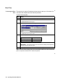
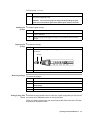
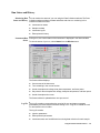
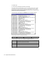
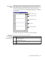
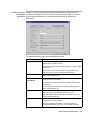
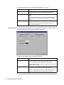
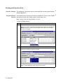
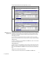
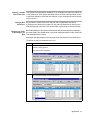
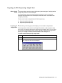
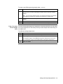
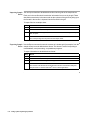
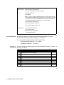
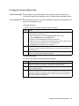
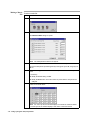
To create an injection list: (continued)
Step
Action
4
The injection list is automatically filled in with information from the selected Sample
Sheet.
Fill in the module information from the Module drop-down list.
5
See “Selecting the Module and Dye Set/Primer File” on page 6-19 if you need help
selecting the correct file.
Note
Drag the column markers at the top of columns to change their width.
Fields in the sequencing injection list form:
Field
Description
Sample Sheet
Displays the selected sample sheet name.
Page Icon
Opens the selected sample sheet.
Length to Detector
The distance between the end of the capillary that is in the
sample and the capillary window. The length you enter will not
affect the configuration of the instrument. It is for record-keeping
purposes only.
Operator
The name you enter here will appear on printed data.
Tube & Sample Name
The sample’s name and position in the autosampler.
Module
The file that contains the specific functions executed to process
samples.
Inj. Secs
The duration of the injection in seconds.
Inj. kV
The voltage during the injection in kilovolts.
Run kV
The voltage during the run in kilovolts.
Run °C
The temperature of the heat plate during the run in degrees
Celsius.
Run Time
The duration of the data collection in minutes. This is less than
the total run time.
Finish Time
Displays the time at which raw data collection for the sample
finished.
Note
You may need to scroll to see the Run Time and Finish Time columns.
6-16 Setting Up DNA Sequencing Experiments
DRAFT June 19, 2001 10:38 am
Liane, 310UG 06 DNASeqExpmt.fm
Editing Injection The following are common things you may want to edit in an injection list.
Lists ♦ Change the order of samples
♦
Add a row to the injection list
♦
Run a sample more than once
♦
Change the module for a sample
See Chapter 5, “Injection Lists,” for more information about the above procedures.
Change Run Parameters
After a module is selected in the injection list, the following fields are automatically
filled in with information from the module:
♦
Injection time
♦
Injection voltage
♦
Run voltage
♦
Run temperature
♦
Run time
You can edit these parameters by selecting a field and typing in a new value. This
changes the run conditions for one run. It does not permanently alter the module.
For information about editing a module, see “Editing Modules” on page 4-14.
Change Sample Sheet Items from the Injection List
The following files on a sample sheet can be changed after viewing the sample sheet
from the injection list:
♦
Dye set/primer
♦
Matrix
About Electrokinetic The electrokinetic injection time and voltage can be varied to regulate the amount of
Injection (Voltage DNA brought into the capillary for analysis.
and Time) The objective is to inject just enough signal into the capillary for adequate peak height
(good signal to noise) while minimizing the peak widths.
There are no specific requirements for the voltage and current during the
electrokinetic injection. Injections at 200 volts/cm are not distinguishable from
injections at 25 volts/cm; however, a lower voltage and current are preferable since the
timing of the injection is more accurate.
Typically, a voltage of 50 volts/cm is used for the electrokinetic injection. At this value,
injection times of 5 to 60 seconds are required to obtain adequate peak height,
depending on the application.
Note
Excessive injection time can cause loss of resolution.
DRAFT June 19, 2001 10:38 am
Liane, 310UG 06 DNASeqExpmt.fm
Setting Up DNA Sequencing Experiments 6-17
Electrophoresis Resolution and basecalling are better at lower field strengths. Increasing the field
Running Voltage for strength allows shorter run times, but reduces base calling accuracy.
DNA Sequencing
For Sequencing Samples Using...
The Standard Running Voltage Is...
POP-4 Standard
240 volts/cm.
For a 47-cm capillary, this translates to 11.3 kV.
The current at this voltage is ~5 µA.
Temperature is 50 °C.
The time required for a 525-base fragment to reach
the detector window is approximately 32 minutes
with these run conditions.
POP-4 RAPID
320 volts/cm.
For a 47-cm capillary, this translates to 15 kV.
The current at this voltage is ~7 µA.
Temperature is 50 °C.
The time required for a 425-base fragment to reach
the detector window is approximately 20 minutes
with these run conditions.
POP-6 and long-read sequencing
200 volts/cm.
For a 61-cm capillary, this translates to 12.2 kV.
The current at this voltage is 4 to 6 µA.
The time required for a 600-base fragment to reach
the detector window is approximately 120 minutes
with these run conditions.
POP-6 and RAPID sequencing
320 volts/cm.
For a 47-cm capillary, this translates to 15 kV.
The current at this voltage is 5 to 8 µA.
The time required for a 400-base fragment to reach
the detector window is approximately 36 minutes
with these run conditions.
Note The required times listed in the above table are approximations only. The times can vary
from instrument to instrument.
Electrophoresis The temperature limits of the heat plate are 60 °C down to 5 °C above room
Temperature temperature.
Note There is no active cooling system on the 310 Genetic Analyzer. You cannot set the heat
plate to a temperature lower than the ambient temperature.
About You can change the running time for special requirements. For example, you can
Electrophoresis shorten the data collection time if you only need information about short extension
Running Time products.
6-18 Setting Up DNA Sequencing Experiments
DRAFT June 19, 2001 10:38 am
Liane, 310UG 06 DNASeqExpmt.fm
Selecting the Module and Dye Set/Primer File
Overview DNA sequencing on the 310 Genetic Analyzer requires you to have these types of
files:
♦
Module
♦
Basecaller
♦
Dye set/primer
♦
Matrix
You select the particular files appropriate to your experiment on the sample sheet and
injection list.
Updated Files The module, basecaller, and dye set/primer files are supplied with the Data Collection
software. Updated files can be obtained from:
♦
Applied Biosystems Web site
http://www.appliedbiosystems.com
♦
Applied Biosystems Technical Support, or from your local field applications
specialist (call your local sales office for more information).
For new applications, a disk containing the files is often included with the reagent kit.
Matrix files are all created using the Sequencing Analysis software. See the
ABI PRISM DNA Sequencing Analysis Software User Guide.
Modules Modules are selected in the Module column in the injection list. The reference table on
pages 6-20 and 6-21 will help you to select the appropriate module.
If a custom module is necessary, see “Editable Parameters” on page 4-14.
Mobility Set/Primer The dye set/primer files (also known as mobility files) are selected in the Dye
Files Set/Primer column in the injection list. They contain information that adjusts the
sample data collected during electrophoresis for:
♦
The dye set
♦
Mobility of the primers or terminators
The dye set/primer file contains mobility correction data for the sample. Note that the
dye set/primer file choice must be consistent with the sequencing reaction chemistry,
polymer, and filter set.
Select the dye set/primer file through the sample sheet. The reference table on pages
6-20 and 6-21 will help you select the appropriate dye set/primer file.
Note
Dye Set/Primer files cannot be edited.
\\
Reference Table for The table on pages 6-20 and 6-21 lists the dye/set primer (mobility) files and the
Dye Set/Primer Files modules for DNA sequencing runs.
and Modules
DRAFT June 19, 2001 10:38 am
Liane, 310UG 06 DNASeqExpmt.fm
Setting Up DNA Sequencing Experiments 6-19
6-20 Setting Up DNA Sequencing Experiments
POP-6
BigDye Primers (v. 3)
POP-4
POP-6
POP-4
POP-6
POP-4
POP-6
Standard Terminators
dRhodamine Terminators
BigDye Terminators
(v. 1 and v. 2)
POP-6
BigDye Terminators (v. 3)
POP-4
Polymer
Chemistry
DP310POP4{BDv3-M13Rev}v1.mob
DP310POP4{BDv3-21M13}v1.mob
DP310POP4{BDv3-M13Rev}v1.mob
DP310POP4{BDv3-21M13}v1.mob
DP310POP6{BDv3-M13Rev}v1.mob or
DTPOP6{BDSet-M13Reverse}.mob
DP310POP6{BDv3-21M13}v1.mob or
DTPOP6{BDSet-21M13}.mob
DP310POP6{BDv3-M13Rev}v1.mob or
DTPOP6{BDSet-M13Reverse}.mob
DP310POP6{BDv3-21M13}v1.mob or
DTPOP6{BDSet-21M13}.mob
P4RapidSeq(1mL)E.md4
P4StdSeq(1mL)E.md4
SeqPOP6Rapid(1 mL)E.md4
SeqPOP6(1mL)E.md4
SeqPOP6Rapid(1 mL)A.md4
DTPOP6.mob
Primers
SeqPOP6(1mL)A.md4
P4RapidSeq(1mL)E.md4
DT310POP4{dRhod}v1.mob
DTPOP6.mob
P4StdSeq(1mL)E.md4
DT310POP4{dRhod}v1.mob
SeqPOP6Rapid(1mL)E.md4
DT310POP6{dRhod}v2.mob or
DTPOP6{dRhodSet-AnyPrimer}.mob
P4RapidSeq(1mL)E.md4
SeqPOP6(1mL)E.md4
DT310POP4{BD}v1.mob
DT310POP6{dRhod}v2.mob or
DTPOP6{dRhodSet-AnyPrimer}.mob
P4StdSeq(1mL)E.md4
SeqPOP6Rapid(1mL) E.md4
DT310POP6{BD}.mob or
DTPOP6{BDSet-AnyPrimer}.mob
DT310POP4{BD}v1.mob
SeqPOP6(1mL)E.md4
P4RapidSeq(1mL)E.md4
DT310POP4{BDv3}v1.mob
DT310POP6{BD}.mob or
DTPOP6{BDSet-AnyPrimer}.mob
P4StdSeq(1mL)E.md4
SeqPOP6Rapid(1 mL) E.md4
DT310POP6{BDv3}v1.mob
DT310POP4{BDv3}v1.mob
SeqPOP6(1mL)E.md4
Module
DT310POP6{BDv3}v1.mob
Terminators
Dyer Set/Primer (Mobility) File
310POP4
310POP4
310POP6
310POP6
310POP6
310POP6
310POP4
310POP4
310POP6
310POP6
310POP4
310POP4
310POP6
310POP6
310POP4
310POP4
310POP6
310POP6
Base
Caller
47 cm x 50 µ
47 cm x 50 µ
47 cm x 50 µ
61 cm x 50 µ
47 cm x 50 µ
61 cm x 50 µ
47 cm x 50 µ
47 cm x 50 µ
47 cm x 50 µ
61 cm x 50 µ
47 cm x 50 µ
47 cm x 50 µ
47 cm x 50 µ
61 cm x 50 µ
47 cm x 50 µ
47 cm x 50 µ
47 cm x 50 µ
61 cm x 50 µ
Capillary
Size
green
green
green
pink
green
pink
green
green
green
pink
green
green
green
pink
green
green
green
pink
Capillary
Mark
Setting Up DNA Sequencing Experiments 6-21
POP-6
BigDye Primers
(v. 1)
POP-4
Polymer
Chemistry
Module
DP310POP4{BD-M13Rev}v2.mob
DP310POP4{BD-21M13}v2.mob
DP310POP4{BD-M13Rev}v1.mob
DP310POP4{BD-21M13}v1.mob
DP310POP6{BD-M13Rev}v1.mob or
DTPOP6{BDSet-M13Reverse}.mob
DP310POP6{BD-21M13}v1.mob or
DTPOP6{BDSet-21M13}.mob
DP310POP6{BD-M13Rev}v1.mob or
DTPOP6{BDSet-M13Reverse}.mob
DP310POP6{BD-21M13}v1.mob or
DTPOP6{BDSet-21M13}.mob
P4RapidSeq(1mL)E.md4
P4StdSeq(1mL)E.md4
SeqPOP6Rapid(1 mL)E.md4
SeqPOP6(1mL)E.md4
Primers (continued)
Dyer Set/Primer (Mobility) File
310POP4
310POP4
310POP6
310POP6
Base
Caller
47 cm x 50 µ
47 cm x 50 µ
47 cm x 50 µ
61 cm x 50 µ
Capillary
Size
green
green
green
pink
Capillary
Mark
Starting the Run
Starting the Run Click the Run button in the Injection List window to start the run.
Note If you did not preheat the instrument as suggested under “Preheating the Heat Plate” on
page 3-30, it can take up to 20 minutes for the instrument to heat to 50 °C.
Monitoring the Run During the run, you can monitor the run and your samples. Refer to “Run Status and
History” on page 4-11 for information on monitoring.
Analyzing the Data The Sequencing Analysis software automatically analyzes the samples when the run
finishes if the automatic analyze checkbox on the Sample Sheet is checked.
See the ABI PRISM DNA Sequencing Analysis Software User Guide for more
information.
6-22 Setting Up DNA Sequencing Experiments
DRAFT June 19, 2001 10:38 am
Liane, 310UG 06 DNASeqExpmt.fm
Section: Matrix Files for DNA Sequencing
In This Section This section covers the following topics:
Topic
See Page
About Matrix Files
6-24
Preparing Matrix Standards
6-25
Creating Matrix Files from Matrix Standards
6-27
Creating a Matrix from a Sample
6-30
DRAFT June 19, 2001 10:38 am
Liane, 310UG 06 DNASeqExpmt.fm
Setting Up DNA Sequencing Experiments 6-23
About Matrix Files
Matrix Files Matrix files contain information that corrects for spectral overlap. Spectral overlap
occurs when part of one dye’s emission spectrum falls onto a portion of the detection
hardware that is collecting the fluorescent peak of another dye. Dye sets are created
to minimize spectral overlap, but it still occurs to some extent.
When choosing matrix files in the sample sheet, match the matrix file to the samples
by dye set and sequencing chemistry. For example, samples run with a module file for
Virtual Filter E should be analyzed with a matrix file that was also run with Virtual Filter
E.
The dye set used to create the matrix file must be the same as the dye set used to run
the sample. If you analyze data with a matrix file that does not reflect the conditions of
your run, the run will appear to fail. Reanalyze with the correct matrix file if you have
made this error.
How Many Matrix Create a separate matrix file for each run condition that affects the collection of
Files? spectra. Some examples are:
♦
A new dye is used
♦
The pH of polymers or buffers has changed
♦
A different type of polymer is used
Run the matrix standards under the sample run conditions and make a matrix file. Use
that matrix file to analyze any and all samples run under those conditions.
About Using Matrix Once a matrix file has been created, it can be used for subsequent runs performed:
Files ♦ With the same kit
♦
On the same instrument
♦
Using the same:
–
Modules
–
Set of dyes
–
Polymer
After running the matrix standards, use their sample files to generate a matrix file
using the Sequencing Analysis software.
6-24 Setting Up DNA Sequencing Experiments
DRAFT June 19, 2001 10:38 am
Liane, 310UG 06 DNASeqExpmt.fm
Preparing Matrix Standards
About the Matrix You must create a matrix file the first time you use any sequencing method (i.e., dye
Standards terminators, BigDye terminators, dye primers, etc.). The matrix standards can be
prepared from matrix standard samples or created directly from a sample or sample
standard.
Preparing matrix standards is optional. It is not necessary to use matrix standards to
generate a sequencing matrix. Any sample that yields good raw data can be used to
create a matrix file.
Note BigDye v. 3 matrix standards differ from previous versions of matrix standards. If you are
using BigDye v. 3 matrix standards, follow the protocol outlined in the product insert to generate
a matrix for use with BigDye v. 3 chemistries.
The following are the matrix standards used for DNA sequencing.
♦
ABI PRISM ® dRhodamine Matrix Standards Kit (dR6G, dR110, dTAMRA ™,
dROX ™, LIZ ™)
♦
310/377 v. 3.0 BigDye Matrix Standards Kit
Note
For part number information, see Appendix B, “Consumables.”
An Example Using For this example, the dRhodamine matrix standards are used for generating a matrix
dRhodamine Matrix for most chemistries run with Virtual Filter Set E (BigDye terminator [v. 1.0 and v. 2.0],
Standards BigDye Primer [v. 1.0], dRhodamine terminator). The dRhodamine matrix standards
are:
Tube Label
Color of Raw Data
Base
dR110 Matrix Standard
black
G
dR6G Matrix Standard
green
A
dTAMRA Matrix Standard
blue
C
dROX Matrix Standard
red
T
Matrix standards are stable for 6 months at 2 to 6 °C. Avoid freeze-thaw cycles.
The dRhodamine matrix standards are provided in a ready-to-use format and are
premixed with a blue dye for use on slab gels. The blue dye is not necessary nor is it
detrimental to use it with the 310 Genetic Analyzer.
The colors in the generated matrix (analyzed data) are consistent with current
base-calling conventions, i.e., C is blue, A is green, G is black, and T is red in
analyzed files. See “Color Display of Data” on page 2-21 for more information about
color display in raw and analyzed data.
DRAFT June 19, 2001 10:38 am
Liane, 310UG 06 DNASeqExpmt.fm
Setting Up DNA Sequencing Experiments 6-25
Preparing Matrix ! CAUTION CHEMICAL HAZARD. Template suppression reagent may cause eye, skin,
Standard Samples and respiratory tract irritation. Please read the MSDS, and follow the handling instructions.
Wear appropriate protective eyewear, clothing, and gloves.
To prepare matrix standard samples:
Step
1
Action
For each of the four matrix standards, mix in a sample vial:
♦ 12 µL of TSR
♦ 1 µL of matrix standard
2
Label each vial with the base and dye.
3
Gently vortex the mixture for 3 to 5 seconds.
4
Store the mix at 2 to 6 °C until ready to use.
Note If you are using POP-4, you will need to set up your matrix standard samples using Hi-Di
formamide. See the POP-4 Polymer Sequencing Protocols for the 310 Genetic Analyzer User
Bulletin.
Denaturing the You can denature the matrix standard samples in the thermal cycler with your other
Matrix Standard samples (refer to “Denaturing and Loading Samples” on page 6-9), or follow this
Samples procedure:
Step
Action
1
Heat the sample for 2 minutes at 95 °C.
2
Chill the sample on ice.
3
Hold on ice until ready to load in the autosampler.
6-26 Setting Up DNA Sequencing Experiments
DRAFT June 19, 2001 10:38 am
Liane, 310UG 06 DNASeqExpmt.fm
Creating Matrix Files from Matrix Standards
About This Example In this example, the matrix standards run will be used to make the matrix file for filter
set E (BigDye terminator [v. 1.0 and v. 2.0], BigDye Primer [v. 1.0], or dRhodamine
terminator chemistries). The Sequencing Analysis software is used to analyze the
data. For information on preparing the standards, refer to “Preparing Matrix
Standards.”
Reviewing the Data Before making the matrix file, review the raw data.
To review the raw data using the Sequencing Analysis software:
Step
1
Action
View the raw data for all matrix sample files while in the Sample Manager window of
the Sequencing Analysis software.
IMPORTANT Do not analyze the sample files.
2
In the Raw Data window, verify that the data peaks are present in all four of the
standards and that no anomalies are present.
Note The relative peak amplitude should be less than 4000 (y-axis of raw data
window).
3
Note the matrix standard files with the best data for making the matrix file.
Making a Matrix To make a matrix file from matrix standards:
File
Step
1
Action
In the Sequencing Analysis software:
a. Go to the Sample drop-down list.
b. Select Make Matrix.
2
In the Input file and dye options window:
a. Set the number of sample files to use to 4.
b. Set the number of dyes to 4.
c. Click OK.
DRAFT June 19, 2001 10:38 am
Liane, 310UG 06 DNASeqExpmt.fm
Setting Up DNA Sequencing Experiments 6-27
To make a matrix file from matrix standards: (continued)
Step
3
Action
From the Select Sample File (dye #X) for Matrix Generation:
♦ For [dye #1], browse to the dR6G file. In this example, it should be located in the
Runs folder.
♦ Click Open.
4
Repeat step 3 for all four dyes. Fill in the Select Sample File (dye #X) for Matrix
Generation dialog boxes using the following table:
[dye #X]
Sample File
dye #1
dR6G
dye #2
dTAMRA
dye #3
dROX
dye #4
dR110
Once the fourth file has been selected, the Matrix Maker will compute the matrix.
Note
5
The information in the table is for this example.
When the Matrix Maker has completed computing the new matrix file the following
window will appear:
a. Type in a file name.
b. Click Save.
6-28 Setting Up DNA Sequencing Experiments
DRAFT June 19, 2001 10:38 am
Liane, 310UG 06 DNASeqExpmt.fm
If You Get an Error If you get an error message and the software will not make a matrix:
♦
You may have designated the wrong files.
♦
The signal may be too weak to make a matrix.
♦
The signal may be too high.
Checking the Matrix Check the quality of the matrix by reviewing the:
Quality ♦ Raw data
♦
Analyzed data of the matrix run
To check the raw data, examine the electropherogram of the raw data.
For this example, the matrix standards should display the following colors:
Matrix Standard
Color in Raw Data
dR110
black
dR6G
green
dTAMRA
blue
dROX
red
DRAFT June 19, 2001 10:38 am
Liane, 310UG 06 DNASeqExpmt.fm
Setting Up DNA Sequencing Experiments 6-29
Creating a Matrix from a Sample
Overview It is not necessary to use matrix standards to generate a sequencing matrix. Any
sample that yields good raw data can be used to create a matrix file.
The sequencing standard is used to make a matrix in the procedures below. The
method can be used with other types of samples.
Reviewing the Data Before making the matrix file, review the raw data:
To review the raw data:
Step
1
Action
View the raw data for all matrix sample files while in the Sample Manager window of
the Sequencing Analysis software.
IMPORTANT Do not analyze the sample files.
2
In the Raw Data window, verify that the data peaks are present in all four of the
standards and that no anomalies are present.
Note The relative peak amplitude should be less than 4000 (y-axis of raw data
window).
3
Note the matrix standard files with the best data for making the matrix file.
Making a Matrix To make a matrix file form a sample:
File
Step
1
Action
In the Sequencing Analysis software:
a. Go to the Sample drop-down list.
b. Select Make Matrix.
2
In the Input file and dye options window:
a. Set the number of sample files to use to 1.
b. Set the number of dyes to 4.
c. Click OK.
6-30 Setting Up DNA Sequencing Experiments
DRAFT June 19, 2001 10:38 am
Liane, 310UG 06 DNASeqExpmt.fm
To make a matrix file form a sample: (continued)
Step
3
Action
From the Select Sample File for Matrix Generation:
a. Browse to find the sequencing standard file. It should be in a folder located on
D:\AppliedBio\310\Runs.
b. Click Open. Once the file has been selected, the Matrix Maker will compute the
matrix.
4
When the Matrix Maker has completed computing the new matrix file the following
window will appear:
a. Type a file name.
b. Click Save. The file will be saved in D:\AppliedBio\Shared\Analysis\
Basecaller\Matrix
If You Get an Error If you get an error message and the software will not make a matrix:
♦
You may have designated the wrong files.
♦
The signal may be too weak to make a matrix.
♦
The signal may be too high (over 4000 RFU).
Note
If you do not get adequate signal to make a matrix, you will have to rerun the standard.
DRAFT June 19, 2001 10:38 am
Liane, 310UG 06 DNASeqExpmt.fm
Setting Up DNA Sequencing Experiments 6-31
Checking Matrix This example explains how to apply a matrix to a sample and what to look for.
Quality To check matrix quality:
Step
Action
1
Open the Sample Manager window in the Sequencing Analysis software.
2
Click the Add button.
3
Select the sample files to be analyzed in the directory dialog box and choose
Finish.
4
The P and F checkboxes should not be checked. Bring the Matrix File (Matrix)
column of the Sample Manager window into view by scrolling with the horizontal
scroll bar. Choose the correct matrix for each sample to be analyzed.
5
Click Start.
6
To check the electropherograms, double-click on each file to open it, then choose
the Electropherogram view.
7
If…
Then…
each peak is one color with the other colors flat under it
the matrix is good.
the other colors are not flat under the peaks
the matrix is poor.
If the…
Then…
matrix is good
Save the matrix file for
future use.
matrix is poor
Reanalyze the matrix
run. If this does not
improve the matrix data,
run new matrix
standards.
8
6-32 Setting Up DNA Sequencing Experiments
DRAFT June 19, 2001 10:38 am
Liane, 310UG 06 DNASeqExpmt.fm
Section: Useful Information for Preparing DNA Sequencing Samples
In This Section This section covers the following topics:
Topic
See Page
About DNA Template Preparation
6-34
About DNA Template Quality
6-35
About Primer Design
6-37
About Preparing Sequencing Reactions
6-38
About Cycle Sequencing
6-40
About Preparing Extension Products for Electrophoresis
6-41
DRAFT June 19, 2001 10:38 am
Liane, 310UG 06 DNASeqExpmt.fm
Setting Up DNA Sequencing Experiments 6-33
About DNA Template Preparation
Reference Document Refer to the following documents for more information about the material covered in
this section.
♦
Automated DNA Sequencing Chemistry Guide for more information on DNA
template preparation and specific protocols.
♦
Comparative PCR Sequencing, a Guide to Sequencing-Based Mutation Detection
for more detailed information about PCR sequencing.
DNA Template The DNA purification method you use can affect the quality of the template
Preparation preparation. Some recommendations for purifying DNA templates are given below.
Prepare adequate template to check purity, quantitate the DNA accurately, and
perform the sequencing reactions.
The recommended quantities for sequencing reactions are shown in the table on
page 6-36.
PCR Templates This section provides information regarding PCR template preparation, but it is not
meant to be a detailed guide to PCR amplification. General information on PCR
amplification can be found in the Guide to PCR Enzymes and in the product inserts
included with GeneAmp PCR reagents. For PCR amplification, use GeneAmp PCR
Instrument Systems and GeneAmp PCR Core Reagents.
Cycle sequencing has been found to provide the most reproducible results when
sequencing PCR templates. Although PCR fragments can be difficult to denature with
traditional sequencing methods, cycle sequencing provides several chances to
denature and extend the template, which ensures adequate signal in the sequencing
reaction.
6-34 Setting Up DNA Sequencing Experiments
DRAFT June 19, 2001 10:38 am
Liane, 310UG 06 DNASeqExpmt.fm
About DNA Template Quality
Using Control DNA Always use a control DNA template when preparing your sequencing reactions. This
can help determine whether failed reactions are the result of poor template quality or
sequencing reaction failure.
We recommend M13mp18 as a single-stranded control and pGEM-3Zf(+) as a
double-stranded control. All Applied Biosystems DNA sequencing kits provide pGEM
control DNA and a –21 M13 primer.
Sequencing A sample standard verifies operation of the instrument’s hardware, just as the control
Standards template verifies the correct preparation of the sample template. Running a sample
standard is optional.
Applied Biosystems sells sequencing standards for dye terminator and dye primer
sequencing. Contact your sales representative for more information.
The Cycle Sequencing Standards provide an additional control to help in
troubleshooting electrophoresis runs. The following standards are available:
♦
Dye Primer Cycle Sequencing Standard
♦
Dye Terminator Cycle Sequencing Standard
♦
dRhodamine Terminator Cycle Sequencing Standard
♦
BigDye Terminator Cycle Sequencing Standard
♦
BigDye Terminator v. 3.0 Sequencing Standard
Note
For part number information, see Appendix B, “Consumables.”
Poor Template Inadequate template preparation is the most common cause of sequencing problems.
Preparation Always follow recommended procedures to prepare templates.
The following are characteristics of badly prepared templates:
♦
Noisy data or peaks under peaks
♦
Failed reactions
♦
Weak signal
Contamination Potential contaminants include:
♦
Proteins
♦
RNA or chromosomal DNA
♦
Residual salts
♦
Residual organic chemicals, e.g., phenol, chloroform, and ethanol
DRAFT June 19, 2001 10:38 am
Liane, 310UG 06 DNASeqExpmt.fm
Setting Up DNA Sequencing Experiments 6-35
Amount of DNA to The amount of DNA template used in a sequencing reaction affects the quality of the
Use data. Too much template makes data appear top heavy with strong peaks at the
beginning of the run that fade rapidly. Too little template or primer reduces the signal
strength and peak height. In the worst case, the noise level increases so that bases
cannot be called. The table below shows the recommended quantities for each
method.
Recommended DNA template quantity for each chemistry:
Cycle Sequencing Chemistry
Dye
Primer
Dye Terminator
dRhodamine
Terminator
BigDye
Primer
BigDye
Terminator
100 to 200 bp
2 to 5 ng
1 to 3 ng
1 to 3 ng
2 to 5 ng
1 to 3 ng
200 to 500 bp
5 to 10 ng
3 to 10 ng
3 to 10 ng
5 to 10 ng
3 to 10 ng
Template
PCR product:
500 to 1000 bp
10 to 20 ng
5 to 20 ng
5 to 20 ng
10 to 20 ng
5 to 20 ng
1000 to 2000 bp
20 to 50 ng
10 to 40 ng
10 to 40 ng
20 to 50 ng
10 to 40 ng
>2000 bp
50 to 150 ng
40 to 100 ng
40 to 100 ng
50 to 150 ng
40 to 100 ng
single-stranded
150 to 300 ng
100 to 250 ng
50 to 100 ng
200 to 400 ng
50 to 100 ng
double-stranded
300 to 600 ng
200 to 500 ng
200 to 500 ng
200 to 800 ng
200 to 500 ng
cosmid, BAC
0.5 to 1.0 µg
0.5 to 2.0 µg
not
recommended
300 to 600 ng
300 to 600 ng
genomic DNA
6-36 Setting Up DNA Sequencing Experiments
not recommended
2 to 3 µg
DRAFT June 19, 2001 10:38 am
Liane, 310UG 06 DNASeqExpmt.fm
About Primer Design
Primer Design The choice of primer sequence, method of primer synthesis, and approach to primer
purification can have a significant effect on the quality of the sequencing data obtained
in dye terminator cycle sequencing reactions. Dye primer cycle sequencing kits
include dye-labeled primers that are already optimized and quantitated.
For troubleshooting information, refer to “Primer Problems” on page 8-3.
DRAFT June 19, 2001 10:38 am
Liane, 310UG 06 DNASeqExpmt.fm
Setting Up DNA Sequencing Experiments 6-37
About Preparing Sequencing Reactions
Reagent Age and The freshest reagents are likely to perform the best. The following methods are
Reaction Storage recommended for guaranteeing reagent freshness.
♦
Store reagents at –15 to –25 °C when not in use, and thaw completely at room
temperature or in an ice bath (do not heat) before use.
Note Do not use a frost-free freezer. The automatic cycling of the temperature for defrosting
can damage reagents.
♦
Avoid excess (more than ten) freeze-thaw cycles. Aliquot reagents in smaller
amounts if necessary.
♦
Shield reagents and sequencing reactions from light. Fluorescent dyes are
susceptible to bleaching.
♦
If you would like to store sequencing reactions for future use, purify and dry them.
Store at –15 to –25 °C in a non-frost-free freezer.
Reaction Tubes The type of tube required depends on the type of thermal cycler used. For the DNA
Thermal Cycler (TC1) and DNA Thermal Cycler 480, use 0.5-mL GeneAmp
Thin-Walled PCR tubes. For the GeneAmp PCR Systems 9700, 9600, and 2400, use
0.2-mL MicroAmp PCR tubes. If using the CATALYST 800 or ABI PRISM 877 Integrated
Thermal Cycler, refer to your instrument user’s manual for reaction setup.
Thermal Cyclers The type and performance of the thermal cycler used to prepare sequencing reactions
can affect the quality of the reactions. Ensure that the thermal cycler is calibrated
regularly by the manufacturer and that ramping rates are 1 °C/second.
BigDye Terminators The procedures given here are for the ABI PRISM BigDye Terminator Cycle
Sequencing Ready Reaction Kits. Refer to the Automated DNA Sequencing
Chemistry Guide for information about other chemistries.
6-38 Setting Up DNA Sequencing Experiments
DRAFT June 19, 2001 10:38 am
Liane, 310UG 06 DNASeqExpmt.fm
Cycle Sequencing 1X Reactions
Reaction Types
Step
1
Action
For each reaction, add the following reagents to a separate tube:
Reagent
Quantity
BigDye Terminator Ready Reaction Mix
8.0 µL
Template
–
single-stranded DNA
50 to 100 ng
double-stranded DNA
200 to 500 ng
PCR product DNA
2 to 100 ng
(depending on size)
Primer
3.2 pmol
Deionized water
q.s.
Total Volume
20 µL
2
Mix well and spin briefly.
3
If using the DNA Thermal Cycler (TC1) or DNA Thermal Cycler 480:
Overlay the reaction mixture with 40 µL of light mineral oil.
DRAFT June 19, 2001 10:38 am
Liane, 310UG 06 DNASeqExpmt.fm
Setting Up DNA Sequencing Experiments 6-39
About Cycle Sequencing
Overview These protocols have been optimized for all Applied Biosystems thermal cyclers,
including the DNA Thermal Cycler (TC1), the DNA Thermal Cycler 480, the CATALYST
800 Molecular Biology LabStation, the 877 Integrated Thermal Cycler, and the
GeneAmp PCR Systems 9700, 9600, and 2400. The protocols contained in this
section should work for all seven instruments.
If you use a thermal cycler not manufactured by Applied Biosystems, you may need to
optimize thermal cycling conditions. Ramping time is very important. If the thermal
ramping time is too fast (>1 °C/sec), poor (noisy) data may result.
For more information, refer to the chemistry protocols.
Conditions for These protocols are used for the BigDye terminator chemistry. These conditions work
BigDye Terminators for a variety of templates and primers. However, if necessary, these parameters can
be changed to suit particular situations, including the following:
♦
For short PCR products, you can use reduced numbers of cycles (e.g., 20 cycles
for a 300 bp fragment).
♦
If the Tm of a primer is >60 °C, the annealing step can be eliminated.
♦
If the Tm of a primer is <50 °C, increase the annealing time to 30 seconds or
decrease the annealing temperature to 48 °C.
♦
For templates with high GC content (>70%), heat the tubes at 98 °C for 5 minutes
before cycling to help denature the template.
Cycle Sequencing on GeneAmp 9700, 9600, or 2400
the GeneAmp
GeneAmp 9700, 9600, or 2400.
Thermal Cyclers
Step
Action
1
Place the tubes in a thermal cycler and set the volume to 20 µL.
2
Repeat the following for 25 cycles:
a. Rapid thermal ramp to 96 °C
b. 96 °C for 10 sec.
c. Rapid thermal ramp to 50 °C
d. 50 °C for 5 sec.
e. Rapid thermal ramp to 60 °C
f. 60 °C for 4 min.
3
Rapid thermal ramp to 4 °C and hold until ready to purify.
4
Spin down the contents of the tubes in a microcentrifuge.
6-40 Setting Up DNA Sequencing Experiments
DRAFT June 19, 2001 10:38 am
Liane, 310UG 06 DNASeqExpmt.fm
About Preparing Extension Products for Electrophoresis
About Excess Dye Unincorporated dye terminators must be removed before the samples can be
Terminators analyzed by electrophoresis. Excess dye terminators in sequencing reactions obscure
bases in the early part of the sequence and can interfere with basecalling.
♦
Precipitation methods are cheaper and faster, but they remove less of the
unincorporated dye-labeled terminators that can obscure data at the beginning of
the sequence.
♦
The spin column procedure removes more terminators, but is more costly than
precipitation methods.
For more information, refer to the chemistry protocols (see page 6-5).
DRAFT June 19, 2001 10:38 am
Liane, 310UG 06 DNASeqExpmt.fm
Setting Up DNA Sequencing Experiments 6-41
Setting Up Fragment
Analysis Experiments
7
7
Introduction
In This Chapter Topics in this chapter include the following:
Topic
See Page
Section: Setting Up a Fragment Analysis Run
7-3
About Fragment Analysis
7-4
Performing a Fragment Analysis Experiment
7-5
Denaturing and Loading the Samples
7-7
Preparing the Fragment Analysis Sample Sheet
7-9
Preparing the Fragment Analysis Injection List
7-13
Select the Modules, Analysis Parameters, and Size Standard Files
7-18
Starting the Run
7-20
Section: Matrix Files for Fragment Analysis
7-21
About Matrix Files
7-22
Preparing Matrix Standards
7-23
Creating the GeneScan Matrix File
7-25
DRAFT June 19, 2001 10:38 am
Liane, 310UG 07 FragAnlyExpmt.fm
Setting Up Fragment Analysis Experiments 7-1
About This Chapter This chapter summarizes the steps for using the ABI PRISM ® 310 Genetic Analyzer to
run a typical fragment analysis run with pooled DNA.
This chapter assumes you have prepared the 310 Genetic Analyzer as described in
“Preparing the 310 Genetic Analyzer for a Run” on page 3-2.
For more information about operating the instrument, refer to Chapter 3, “Operating
the Instrument Hardware.”
7-2 Setting Up Fragment Analysis Experiments
DRAFT June 19, 2001 10:38 am
Liane, 310UG 07 FragAnlyExpmt.fm
Section: Setting Up a Fragment Analysis Run
In This Section This section covers the following topics:
Topic
See Page
About Fragment Analysis
7-4
Performing a Fragment Analysis Experiment
7-5
Denaturing and Loading the Samples
7-7
Preparing the Fragment Analysis Sample Sheet
7-9
Preparing the Fragment Analysis Injection List
7-13
Select the Modules, Analysis Parameters, and Size Standard Files
7-18
Starting the Run
7-20
DRAFT June 19, 2001 10:38 am
Liane, 310UG 07 FragAnlyExpmt.fm
Setting Up Fragment Analysis Experiments 7-3
About Fragment Analysis
Types of There are many types of experiments that are analyzed using the 310 Genetic
Experiments Analyzer and the ABI PRISM ® GeneScan ® Analysis Software or ABI PRISM ®
GeneMapper ™ Software. They all attempt to determine the size or relative quantity of
DNA fragments. Applied Biosystems sells a number of kits for applications that are
analyzed with GeneScan Analysis software or GeneMapper software. Contact your
sales representative for information.
Applications
Experiments
Microsatellite Analysis
♦ Fluorescent genotyping for genetic
linkage studies
♦ Paternity identification
♦ Forensic identification of samples
♦ Determination of loss of heterozygosity
♦ Microsatellite instability
♦ Trisomy analysis
Amplified Fragment Length Polymorphism
(AFLP ™) Analysis
♦ Gene mapping using AFLP analysis
Gene Expression Profiling
♦ Differential display
♦ Quantitative expression of gene products
♦ RNase protection assays
Mutation Detection
♦ SNP Genotyping
♦ Single strand conformation
polymorphisms (SSCP)
♦ Heteroduplex mobility assays (HMA)
♦ Mismatch cleavage
♦ Oligonucleotide ligation assays (OLA)
♦ Allele-specific PCR
7-4 Setting Up Fragment Analysis Experiments
DRAFT June 19, 2001 10:38 am
Liane, 310UG 07 FragAnlyExpmt.fm
Performing a Fragment Analysis Experiment
Materials Required To run a fragment analysis experiment you will need the following items. For part
number information for the consumables, see Appendix B, “Consumables.”
Lab Equipment
Filter-sterilized, deionized water
Disposable, non-powdered, chemical-resistant gloves
Microcentrifuge or centrifuge adapted for spinning microtiter plates (96-well tray)
Small-volume, calibrated pipette and tips (we recommend the Gilson Pipetman)
One of the following thermal cyclers from Applied Biosystems:
♦ GeneAmp ® PCR System 9600
♦ GeneAmp ® PCR System 9700
Note If the GeneAmp PCR System 2400 or DNA Thermal Cycler 9600/9700 will be used
to denature your samples, you will need the appropriate materials (i.e., tubes, tray, etc.) for
these thermal cyclers. You will also have to transfer the samples to either the 96- or 48-well
sample tray to load the samples on the 310 Genetic Analyzer.
Consumables
ABI
PRISM ®
310 10X Genetic Analyzer Buffer with EDTA
One of the following polymers:
♦ POP-4 ™ Performance Optimized Polymer
♦ GeneScan Polymer
Hi-Di ™ formamide
Matrix standard (see page 7-23)
One of the following size standards:
♦ GeneScan ®-400HD [ROX] ™
♦ GeneScan ®-500 [ROX] ™
♦ GeneScan ®-500 [LIZ] ™
♦ GeneScan ®-120 [LIZ] ™
Two 4.0-mL Genetic Analyzer buffer vials with cap adapters
One 1.0-mL glass syringe (or one 2.5-mL glass syringe)
Two septa for the 4.0-mL buffer vials
ABI PRISM ® 310 Genetic Analyzer Capillary, 47-cm, 50-µ i.d., labeled with a green mark
Note Do not use GeneScan capillaries labeled with a yellow mark (P/N 401823) with
POP-4 polymer. Resolution will be unsatisfactory if these capillaries are used with POP-4
polymer.
DRAFT June 19, 2001 10:38 am
Liane, 310UG 07 FragAnlyExpmt.fm
Setting Up Fragment Analysis Experiments 7-5
One sample tray and related accessories:
♦ 96-well tray:
One MicroAmp ® tray/retainer set
Two to ten 0.2-mL MicroAmp ® reaction tubes
One MicroAmp ® base
One adaptor
Note If you are using a 9700 Thermal Cycler, and you do not have the
96-well sample tray adaptor (P/N 4305051), then you will have to transfer
the samples from the tray compatible with the 9700 after denaturation to
the 96-well sample tray before placing it on the autosampler.
One MicroAmp ® full plate cover
One Genetic Analyzer septa strip
One Genetic Analyzer retainer clip
♦ 48-well tray:
48-well sample tray (4.0-mL)
0.5-mL sample tubes
Septa for 0.5-mL sample tubes
1.5-mL Eppendorf tube
Software Required The following software is required for the procedures described in this chapter.
♦
ABI PRISM ® 310 Data Collection Software, v. 3.0 or higher
♦
One of the following data analysis software applications:
–
GeneScan Analysis software, v. 3.7 or higher
–
GeneMapper software, v. 1.0 or higher
Summary of To perform a fragment analysis experiment with pooled DNA using the 310 Genetic
Procedures Analyzer, you need to:
Step
Procedure
See Page
1
Set up the 310 Genetic Analyzer as described in Chapter 3,
“Operating the Instrument Hardware.”
3-2
2
Prepare the matrix standards (if necessary)
7-23
3
Amplify and denature (if necessary) the samples
7-7
4
Load the samples
7-8
5
Prepare a sample sheet
7-9
6
Prepare an injection list
7-13
7
Start the run
7-20
8
Create the matrix file (if necessary)
7-23
9
Analyze the data
7-20
7-6 Setting Up Fragment Analysis Experiments
DRAFT June 19, 2001 10:38 am
Liane, 310UG 07 FragAnlyExpmt.fm
Denaturing and Loading the Samples
About the Sample
Preparation
Reagents
About Formamide
and Samples in
Formamide
The following procedures are for preparing the samples using POP-4 protocols, which
use highly deionized formamide (Hi-Di formamide) as the denaturant.
! WARNING CHEMICAL HAZARD. Formamide is harmful if absorbed through the skin
and may cause irritation to the eyes, skin, and respiratory tract. It may cause damage to the
central nervous system and the male and female reproductive systems, and is a possible birth
defect hazard. Please read the MSDS, and follow the handling instructions. Wear appropriate
protective eyewear, clothing, and gloves.
The protocol uses formamide as a sample preparation reagent. Fresh formamide must
be deionized and aliquotted into smaller volumes for storage. Each aliquot should be
adequate for about one week’s work.
When working with formamide, keep these points in mind:
♦
Aliquot in small volumes, such as 0.5 to 1.0 mL. This will prevent multiple
freeze-thaw cycles which exposes the sample to water, which promotes
formamide degradation.
♦
Store aliquots of formamide at −20 °C for up to 3 months. Formamide stored at
4 °C is good for about 1 week.
♦
At room temperature, samples in formamide are stable for a maximum of
48 hours.
Although not recommended on a routine basis, you can keep samples prepared in
formamide frozen for no more than three days before running on the 310 Genetic
Analyzer with no detectable loss in resolution.
Preparing the Unlike DNA sequencing samples, fragment analysis samples are not typically
Formamide-Sample quantitated on a spectrophotometer prior to loading on the 310 Genetic Analyzer.
Mix To ensure reproducibility of results for all samples, prepare the formamide-size
standard mix using the 12:1 ratio of reagents stated in the procedure below.
To prepare the formamide-sample mix:
Step
1
Action
Prepare the 12:1 formamide-size standard:PCR sample mix.
a. Prepare the formamide-size standard
– 12.0 µL deionized formamide
– 0.5 µL size standard (such as GeneScan ®-400HD [ROX] ™)
b. Mix in a sample vial:
– 12.0 µL formamide-size standard
– 1 µL PCR sample
c. Label the vial.
d. Vortex the mixture gently for 3 to 5 seconds.
e. Spin down the mixture.
f. Store the mix at 2 to 6 °C until ready to use.
2
Cover the tube with a septum and vortex well.
DRAFT June 19, 2001 10:38 am
Liane, 310UG 07 FragAnlyExpmt.fm
Setting Up Fragment Analysis Experiments 7-7
To prepare the formamide-sample mix: (continued)
Step
3
Action
Heat the mixture for 2 minutes at 95 °C and place it on ice until ready to place in the
instrument.
Diluting the The 12:1 ratio of formamide-size standard:PCR sample mix is usually an adequate
Formamide-Sample dilution; however, if the peaks go off-scale at this dilution, further dilute the mixture.
Mix To dilute the mixture, transfer into a sample tube:
♦
1 µL of the 12:1 formamide-size standard:PCR sample mix
♦
9 µL of formamide
Minimum Sample The minimum sample volume per tube is 10 µL. If you choose to use 10 µL samples,
Volume routine autosampler calibration is necessary (see “Calibrating the Autosampler” on
page 3-4).
You can use a single sample for more than one analysis. Either inject out of one
sample tube repeatedly, or split the sample into several tubes.
Loading the Samples Load the samples into the autosampler as follows:
Step
1
Action
If using a 96-well tray, fit the tray onto the adaptor base.
IMPORTANT The tube arrangement and order of the samples in the tray and on
the sample sheet must be the same. Make note of the tube arrangement you use,
so that you can prepare the sample sheet correctly.
2
Seal each tube with a septum, and place the tray into the autosampler.
7-8 Setting Up Fragment Analysis Experiments
DRAFT June 19, 2001 10:38 am
Liane, 310UG 07 FragAnlyExpmt.fm
Preparing the Fragment Analysis Sample Sheet
About Sample The sample sheet associates sample information (name and type of analysis) with a
Sheets sample tube position in the autosampler.
Fill out the sample sheet in the Data Collection software to name each sample,
associate it with a position in the autosampler, and make some choices about the
sample’s processing.
There are two kinds of sample sheets for fragment analysis:
♦
GeneScan 48 sample tubes
♦
GeneScan 96 sample tubes
Preparing a Sample The first time you use a group of samples, you must create a sample sheet.
Sheet
The sample sheet will be saved in the Sample Sheet folder on your computer. If you
use the same type of kit or group of samples again, select the previously created
sample sheet. If there is already a sample sheet prepared for the kit, go to “Preparing
an Injection List” on page 7-13.
To create a new fragment analysis sample sheet:
Step
Action
1
In the Data Collection software, select New from the File menu.
2
Click GeneScan Smpl Sheet 48 Tube or GeneScan Smpl Sheet 96 Tube as
appropriate.
3
The Sample Sheet window appears.
Note
DRAFT June 19, 2001 10:38 am
Liane, 310UG 07 FragAnlyExpmt.fm
Drag the column markers at the top of columns to change their width.
Setting Up Fragment Analysis Experiments 7-9
To create a new fragment analysis sample sheet: (continued)
Step
4
Action
Follow steps 5 through 12 to prepare the sample sheet (with or without matrix
standards). The screens below are examples of GeneScan sample sheets.
GeneScan sample sheet with matrix standard samples:
Note Include the matrix standard samples if you need to create a matrix file for
the dye set.
IMPORTANT Do not specify a color in the Std column for the matrix samples.
GeneScan sample sheet without matrix standard samples:
5
Select 4 Dyes or 5 Dyes from the drop-down list in the upper right corner.
6
In the Sample Name column, enter the name of each of the samples.
7
In the Collection Name column, select a collection name for the sample. This is
necessary only if you will be uploading the samples into the Sequence Collector
software.
Note If you are using collection names, you must first enter them in the Collection
Info Preferences window (see “Collection Info Preferences” on page 4-28).
7-10 Setting Up Fragment Analysis Experiments
DRAFT June 19, 2001 10:38 am
Liane, 310UG 07 FragAnlyExpmt.fm
To create a new fragment analysis sample sheet: (continued)
Step
8
Action
Click next to the color for the standard the Std column to specify a color for size
standard. The selected color will be marked with a diamond. For 4 dyes, this will be
red; for 5 dyes, this will be orange.
Note Remember, the tube arrangement in the tray and the order of the samples
on the sample sheet must be the same.
9
In the Sample Info column, copy the Sample Name information. See “About the
Sample Info Column,” below.
10
In the Comments column, enter any additional comments that you want to link to the
samples.
11
From the File menu, select Save As.
12
Name the sample sheet, and press Return to save it in the Sample Sheets folder.
About the Sample We recommend copying the sample names into the Sample Info column. This
Info Column information may be useful in other downstream applications.
To fill out the Sample Info column:
Step
Action
1
Select the column titled Sample Name.
2
From the Edit menu, select Copy.
3
Select the column titled Sample Info.
4
From the Edit menu, select Paste.
About the Color and Color
Std Columns These are the colors of your dyes. There will be either four or five colors, depending on
your dye set.
Set the colors in the Dye Indicators preferences.
Std
A marker ( ) appears in this column to indicate that a particular dye in your sample is
a standard.
The field should be empty when running matrix standards and filled under most other
circumstances.
If you do not choose to launch and run the GeneScan Analysis software automatically
or if you reanalyze data later, you can make changes to this selection through the
analysis software. Raw data is collected for all colors, but only the colors for which a
sample is present are automatically analyzed by the GeneScan Analysis software.
DRAFT June 19, 2001 10:38 am
Liane, 310UG 07 FragAnlyExpmt.fm
Setting Up Fragment Analysis Experiments 7-11
Using a Previously If you are running the same group of samples for a second or third time, you can use
Created Sample the original sample sheet. Select the previously created sample sheet when filling out
Sheet the injection list.
To modify an existing sample sheet:
Step
Action
1
Open the Sample Sheet. It is stored in the Sample Sheet folder.
2
Make changes and save the Sample Sheet.
♦ To keep the original, choose Save As and give the sample sheet a new name.
♦ To overwrite the original, choose Save without renaming the Sample Sheet.
3
Select the modified Sample Sheet when filling out the Injection List.
Importing Sample You can import data from tab-delimited text files into the grids of the sample sheet.
Sheets
Each row in the text file should contain the information for one row in the grid. These
data fields must also be in the same order as the columns of the grid. Everything up to
the first tab in the text file is imported into the first field in the grid.
To import files into a sample sheet:
Step
Action
1
Create a new sample sheet.
2
From the File menu, select Import.
3
In the dialog box that appears, choose the name of the file containing the text you
wish to import.
4
Click OK.
The corresponding text is imported into the sample sheet.
Exporting Sample Use the Export command to save the contents of a window grid (for example, from the
Sheets sample sheet) into a tab-delimited text format. This format is useful for exporting to
most database, word processing, or spreadsheet programs.
To export information to tab-delimited text format:
Step
Action
1
Create a new sample sheet and fill in the necessary information.
2
From the File menu, select Export.
3
Type a file name in the dialog box that appears.
4
Click OK.
This creates a text file that can be imported into another 310 Genetic Analyzer’s
sample sheets or viewed in Microsoft ® Excel or Word applications.
7-12 Setting Up Fragment Analysis Experiments
DRAFT June 19, 2001 10:38 am
Liane, 310UG 07 FragAnlyExpmt.fm
Preparing the Fragment Analysis Injection List
Overview The injection list specifies the order for running samples, how many injections are
made from each sample, and the module and running conditions for each injection.
For a fragment analysis run, you will use the GeneScan Injection List. From this, you
can select the:
♦
Sample sheet
♦
Module file
♦
Matrix file
♦
Analysis parameters file
♦
Size standard file
For additional information about editing injection lists, see Chapter 5, “Injection Lists.”
Preparing an To create a new fragment analysis injection list:
Injection List
Step
Action
1
In the Data Collection software, go to the File menu and select New. The following
window appears.
2
Click GeneScan Injection List.
DRAFT June 19, 2001 10:38 am
Liane, 310UG 07 FragAnlyExpmt.fm
Setting Up Fragment Analysis Experiments 7-13
To create a new fragment analysis injection list: (continued)
Step
3
Action
Select the sample sheet for the experiment from the drop-down list.
This transfers the sample sheet information automatically to the injection list.
The following is an example of an injection list with matrix standard samples:
The following is an example of an injection list without matrix standard samples:
Note
4
Drag the column markers at the top of columns to change their width.
Complete the injection list:
a. Enter your name as the Operator.
b. Open the Module drop-down list for each sample, and select a module.
Note When a 5-dye sample sheet is imported into an injection list, only 5-dye
modules are available in the drop-down list. Similarly, when a 4-dye sample sheet is
imported, only 4-dye modules are available.
c. Leave the remaining parameters at their default settings.
5
In the Matrix File column, select the name of the matrix being used.
6
Check the Auto Anlz box to launch the GeneScan Analysis software automatically.
7
Check the Auto Prt box to print the data automatically
7-14 Setting Up Fragment Analysis Experiments
DRAFT June 19, 2001 10:38 am
Liane, 310UG 07 FragAnlyExpmt.fm
GeneScan Injection Drag the markers at the top of columns to change their width.
List Fields
Fields in the GeneScan injection list form:
Field
Description
Sample Sheet
Displays the selected sample sheet.
Page icon
Opens the selected sample sheet.
Length to Detector
The distance between the end of the capillary that is in the
sample and the capillary window. The length you enter in the
Injection List will not affect the physical configuration of the
instrument. It is for record-keeping purposes only.
Operator
The name you enter here will appear on printed data.
Tube & Sample Name
The sample’s name and position in the autosampler.
Module
The file that contains the specific functions executed to process
samples.
Inj. Secs
The duration of the injection in seconds.
Inj. kV
The voltage during the injection in kilovolts.
Run kV
The voltage during the run in kilovolts.
Run °C
The temperature of the heat plate during the run in degrees
Celsius.
Run Time
The duration of the data collection in minutes. This is less than
the total run time.
Matrix file
The matrix file to be used for each sample file.
Auto Anlz
Determines if raw data is analyzed automatically by the
GeneScan Analysis software.
Analysis Parameters
The parameters file to be used.
Size Standard
The size standard file to be used.
Auto Prt
Determines if analyzed data is printed automatically.
DRAFT June 19, 2001 10:38 am
Liane, 310UG 07 FragAnlyExpmt.fm
Setting Up Fragment Analysis Experiments 7-15
Editing Injection The following are common things you may want to edit in an injection list.
Lists ♦ Change the order of samples
♦
Add a row to the injection list
♦
Run a sample more than once
♦
Change the module for a sample
See Chapter 5, “Injection Lists,” for more information about the above procedures.
Change Run Parameters
After a module is selected in the injection list, the following fields are automatically
filled in with information from the module:
♦
Injection time
♦
Injection voltage
♦
Run voltage
♦
Run temperature
♦
Run time
You can edit these parameters by selecting a field and typing in a new value. This
changes the run conditions for one run. It does not permanently alter the module.
For information about editing a module, see “Editing Modules” on page 4-14.
Change Sample Sheet Items from the Injection List
The following files on a sample sheet can be changed after viewing the sample sheet
from the injection list:
♦
Analysis parameters
♦
Size standards
The color of standards and the colors present in a sample can also be changed on
GeneScan sample sheets.
Note You cannot switch between 4 Dyes and 5 Dyes in the sample sheet if the sample sheet
is linked to an injection list.
7-16 Setting Up Fragment Analysis Experiments
DRAFT June 19, 2001 10:38 am
Liane, 310UG 07 FragAnlyExpmt.fm
About Electrokinetic The electrokinetic injection time and voltage can be varied to regulate the amount of
Injection (Voltage DNA brought into the capillary for analysis.
and Time) The objective is to inject just enough signal into the capillary for adequate peak height
(good signal to noise) while minimizing the peak widths.
There are no specific requirements for the voltage and current during the
electrokinetic injection. Injections at 200 volts/cm are not distinguishable from
injections at 25 volts/cm; however, a lower voltage and current are preferable since the
timing of the injection is more accurate.
Typically, a voltage of 50 volts/cm is used for the electrokinetic injection. At this value,
injection times of 5 to 60 seconds are required to obtain adequate peak height,
depending on the application.
Recommended conditions are provided in the modules; however, you may customize
the parameters.
Note
Excessive injection time can cause loss of resolution.
Electrophoresis Resolution is better at lower field strengths. Increasing the field strength allows shorter
Running Voltage for run times, but reduces resolution.
Fragment Analysis
For sequencing samples using...
The standard running voltage is...
POP-4 Standard
319 volts/cm.
For a 47-cm capillary, this translates to 15 kV.
The current at this voltage is 7 to 9 µA.
Temperature is 60 °C.
The time required for a 400-base fragment to reach
the detector window is approximately 25 minutes
with these run conditions.
Note The required time listed in the above table is an approximation only. The times can vary
from instrument to instrument.
Electrophoresis The temperature limits of the heat plate are 60 °C down to 5 °C above room
Temperature temperature.
Note There is no active cooling system on the 310 Genetic Analyzer. You cannot set the heat
plate to a temperature lower than the ambient temperature.
About You can change the running time for special requirements. For example, you can
Electrophoresis shorten the data collection time if you only need information about short extension
Running Time products.
Typically, you set the electrophoresis running time at an interval 10% higher than the
average migration time of the maximum fragment size of interest to ensure sufficient
data collection.
DRAFT June 19, 2001 10:38 am
Liane, 310UG 07 FragAnlyExpmt.fm
Setting Up Fragment Analysis Experiments 7-17
Select the Modules, Analysis Parameters, and Size Standard Files
Overview Fragment analysis on the 310 Genetic Analyzer requires you to have these types of
files:
♦
Module
♦
Size standard
♦
Analysis parameters
♦
Matrix
You select the particular files appropriate to your experiment on the sample sheet and
injection list.
Updated Files The module files are supplied with the Data Collection software. Updated files can be
obtained from:
♦
Applied Biosystems Web site
http://www.appliedbiosystems.com
♦
Applied Biosystems Technical Support, or from your local technical applications
specialist (call your local sales office for more information).
For new applications, a disk containing the files is often included with the reagent kit.
Size standard, analysis parameters, are supplied with the GeneScan Analysis
software. Matrix files are created using GeneScan Analysis software. See the
ABI PRISM GeneScan Analysis Software User Guide for more information.
Modules Modules are selected in the Module column in the injection list. Select the module
based on the polymer, glass syringe size, dye set, and application you are using.
Reference Table for Use the following table as a guide when selecting a module.
Modules
Chemistry
PRISM ®
Linkage Mapping Sets
ABI
HD5, MD10, LD20
Module
GS STR POP4 (1.0mL) D
Mouse mapping markers
Custom primers for fragment analysis
AFLP ™ Plant Mapping Kits I and II
GS STR POP4 (1.0mL) F
StockMarks ® Kits
AFLP ™ Microbial Identification Kit
AmpFlSTR ® product line (except
Identifiler)
SNaPshot ™ Multiplex Kit
GS STR POP4 (1.0mL) E5
High throughput primers for fragment
analysis
GS STR POP4 (1.0 mL) G5
5-dye LMS
Custom primers for fragment analysis
AmpFl STR ® Identifiler ™ PCR
Amplification Kit
7-18 Setting Up Fragment Analysis Experiments
DRAFT June 19, 2001 10:38 am
Liane, 310UG 07 FragAnlyExpmt.fm
Chemistry
Module
Cystic Fibrosis
GS STR POP4 (1.0 mL) C
Fragile X Length Polymorphism Assay
If you need a custom module, see “Editing Modules” on page 4-14.
Size Standard Files About Size Standard Files
The size standard file holds the results of a run performed with fragments of known
length. The file can be used to analyze other runs performed under the same
conditions to determine the size of fragments of unknown length.
Applied Biosystems offers several size standard kits. Contact your sales
representative for more information.
Generating New Size Standard Files
To generate new size standard files, set up the instrument and run the mixture of
known-length fragments as a single sample. Create a new size standard file using the
GeneScan Analysis software or GeneMapper software. See the ABI PRISM GeneScan
Analysis Software User Guide or the ABI PRISM GeneMapper Software User Guide for
more information.
Analysis Parameters This file holds the default or custom start and stop point for data analysis, the default
Files minimum peak height threshold, and the default size calling method.
New analysis parameters files are created using the GeneScan Analysis software or
GeneMapper software. See the ABI PRISM GeneScan Analysis Software User Guide
or the ABI PRISM GeneMapper Software User Guide for more information.
DRAFT June 19, 2001 10:38 am
Liane, 310UG 07 FragAnlyExpmt.fm
Setting Up Fragment Analysis Experiments 7-19
Starting the Run
Starting the Run Click the Run button in the Injection List window to start the run.
Note If you did not preheat the instrument as suggested under “Preheating the Heat Plate” on
page 3-30, it can take up to 30 minutes for the instrument to heat to 60 °C and begin
electrophoresis.
Monitoring the Run During the run, you can monitor the run and your samples. Refer to “Run Status and
History” on page 4-11 for information on monitoring.
Analyzing Data GeneScan Analysis software automatically analyzes the samples when the run
finishes if the automatic analyze checkbox on the injection list is checked.
Refer to the ABI PRISM GeneScan Analysis Software User Guide for more information.
7-20 Setting Up Fragment Analysis Experiments
DRAFT June 19, 2001 10:38 am
Liane, 310UG 07 FragAnlyExpmt.fm
Section: Matrix Files for Fragment Analysis
In This Section This section covers the following topics:
Topic
See Page
About Matrix Files
7-22
Preparing Matrix Standards
7-23
Creating the GeneScan Matrix File
7-25
DRAFT June 19, 2001 10:38 am
Liane, 310UG 07 FragAnlyExpmt.fm
Setting Up Fragment Analysis Experiments 7-21
About Matrix Files
Matrix Files Matrix files contain information that corrects for spectral overlap. Spectral overlap
occurs when part of one dye’s emission spectrum falls onto a portion of the detection
hardware that is collecting the fluorescent peak of another dye. Dye sets are created
to minimize spectral overlap, but it still occurs to some extent.
When choosing matrix files in the sample sheet, match the matrix file to the samples
by dye set and sequencing chemistry. For example, samples run with a module file for
Virtual Filter G5 should be analyzed with a matrix file that was also run with Virtual
Filter G5.
The dye set used to create the matrix file must be the same as the dye set used to run
the sample. If you analyze data with a matrix file that does not reflect the conditions of
your run, the run will appear to fail. Reanalyze with the correct matrix file if you have
made this error.
How Many Matrix Create a separate matrix file for each run condition that affects the collection of
Files? spectra. Some examples are:
♦
A new dye is used
♦
The pH of polymers or buffers has changed
♦
A different type of polymer is used
Run the matrix standards under the sample run conditions and make a matrix file. Use
that matrix file to analyze any and all samples run under those conditions.
About Using Matrix The matrix file contains the information necessary for software to correct the overlap
Files of the dyes’ emission spectra on the virtual filter. Once a matrix file has been created,
it can be used for subsequent runs performed:
♦
With the same kit or chemistry
♦
On the same instrument
♦
Using the same:
–
Modules
–
Set of dyes
–
Polymer
After running the matrix standards, use their sample files to generate a matrix file
using the GeneScan Analysis software.
7-22 Setting Up Fragment Analysis Experiments
DRAFT June 19, 2001 10:38 am
Liane, 310UG 07 FragAnlyExpmt.fm
Preparing Matrix Standards
About Matrix You must run matrix standards and create a matrix file the first time you use a new
Standards chemistry or change the run conditions.
Do not prepare matrix standards more than 2 hours in advance.
To ensure reproducibility of results for all samples, prepare the matrix standard mix
using the 12:1 ratio of reagents stated in the procedure below.
IMPORTANT Do not add size standard mix to the matrix standard samples.
The following are the matrix standards used for fragment analysis.
♦
Matrix Standard Set DS-02 for filter set E5
(dR6G, dR110, dTAMRA ™, dROX ™, LIZ ™)
♦
Matrix Standard Set DS-33 for filter set G5
(6-FAM ™, VIC ™, NED ™, PET ™, LIZ)
♦
Matrix Standard Set DS-30
(6-FAM, HEX ™, NED, ROX ™) use Fluorescent Amidite Standards kit + NED
♦
Fluorescent Amidite Standards
(6-FAM, HEX, TET ™, ROX, TAMRA ™)
♦
NED matrix standard
♦
VIC matrix standard
♦
Matrix Standard Set DS-32 for filter set F
(5-FAM ™, JOE ™, NED, ROX)
♦
Matrix Standard Set DS-34 (6-FAM, TET, HEX, TAMRA) use Fluorescent Amidite
Standards kit for filter set C
Note
For part number information, see Appendix B, “Consumables.”
Preparing Matrix ! WARNING CHEMICAL HAZARD. Formamide is harmful if absorbed through the skin and
Standard Samples may cause irritation to the eyes, skin, and respiratory tract. It may cause damage to the central
nervous system and the male and female reproductive systems, and is a possible birth defect
hazard. Please read the MSDS, and follow the handling instructions. Wear appropriate
protective eyewear, clothing, and gloves.
To prepare matrix standard samples:
Step
1
Action
For each sample, mix in a sample vial:
a. 1.0-µL matrix standard
b. 12.0-µL deionized formamide
2
Label each vial according to the dye.
3
Gently vortex the mixture for 3 to 5 seconds.
4
Spin down the mixture.
5
Store at 2 to 6 °C until ready to use.
DRAFT June 19, 2001 10:38 am
Liane, 310UG 07 FragAnlyExpmt.fm
Setting Up Fragment Analysis Experiments 7-23
Denaturing the You can denature the matrix standard samples in the thermal cycler with your samples
Matrix Standard or follow this procedure:
Samples
Step
1
Action
If you are using the GeneAmp PCR System 9600 or 9700 to denature your
samples, plan the order in which you will place the samples in the 96-well tray.
Note Each color must have a separate well in plate. Do not mix matrix standards
into one well.
Here is a suggested configuration:
1
2
3
4
5
6
7
8
9
10
11
12
A
Matrix standard
samples are in
A1 through A4.
B
C
D
E
F
GR2074
G
H
2
Heat the sample for 5 minutes at 95 °C.
3
Chill the sample on ice.
4
Hold on ice until ready to load in the autosampler.
7-24 Setting Up Fragment Analysis Experiments
DRAFT June 19, 2001 10:38 am
Liane, 310UG 07 FragAnlyExpmt.fm
Creating the GeneScan Matrix File
About This Example In this example, the matrix standards run will be used to make the matrix file. For
information on preparing the standards, refer to “Preparing Matrix Standard Samples.”
Reviewing the Data Before making the matrix file, review the raw data by viewing and verifying that the raw
data from the standards is good.
Viewing the Raw Data
To view the raw data using the GeneScan Analysis software:
Step
1
Action
Create a new project:
a. Select New from the File menu.
b. Select the Project icon. An untitled Analysis Control window opens.
c. Select Add Sample Files from the Project menu.
d. Find and open the Run Folder for the matrix standards run.
e. Select the four or five sample files representing the blue, green, yellow, red, and
orange (for 5-dye) dye-labeled “runs,” and then click Add.
f. Click Done after the sample files are transferred.
2
In the Analysis Control window, select the four or five matrix standard sample files
by clicking on the first sample file, holding down the mouse button, and releasing on
the last sample file.
3
Choose Raw Data from the Project menu. Electropherograms displaying raw data
from the four matrix standard sample files appear.
Verifying the Raw Data
To verify the raw data in the GeneScan Analysis software:
Step
Action
1
Verify that data peaks are present in each sample. Peak data should be on-scale
and the dye of interest should have a value between 200 to 2000 RFU.
2
Check for any data anomalies, such as an unstable baseline. Rerun samples that
have an unstable baseline.
3
Select a starting point for the matrix data. The starting point for matrix data should
be slightly beyond the point where the primer peak falls back to the baseline. Make
sure you have collected a sufficient number of peaks. A typical fragment analysis
run yields a minimum of seven peaks.
DRAFT June 19, 2001 10:38 am
Liane, 310UG 07 FragAnlyExpmt.fm
Setting Up Fragment Analysis Experiments 7-25
Making a Matrix To make a matrix file:
File
Step
Action
1
From the File menu, select New.
2
Click the Matrix icon.
The Make New Matrix dialog box opens.
Note
3
The example above shows a five-dye set.
Click the B, G, Y, R, and O buttons to choose the standard sample files.
Choose the sample file representing blue dye for B, green dye for G, orange dye for
O, etc.
4
Enter the starting point for each file. The Start At point should be after the primer
peak.
If necessary:
♦ Modify the default setting of 2000.
♦ Modify the Points value. This is the number of points after the start point to be
analyzed.
5
Click OK. A successful matrix opens an untitled Matrix Values window with a 5x5
matrix of numerical values.
Note For a four-dye set, the window displays a 4x4 matrix of numerical values.
For a five-dye set, the window displays a 5x5 matrix of numerical values.
7-26 Setting Up Fragment Analysis Experiments
DRAFT June 19, 2001 10:38 am
Liane, 310UG 07 FragAnlyExpmt.fm
To make a matrix file: (continued)
Step
6
Action
Use the Save As command to name and save the matrix file. Choose a name that
reflects the chemistry and run conditions.
Checking the Matrix Check the quality of the matrix by reviewing the:
Quality ♦ Values in the Matrix Values window
♦
Analyzed data of the matrix run
To review the values in the Matrix Values window:
Step
1
Action
View the Matrix Values window.
Note For a four-dye set, the window displays a 4x4 matrix of numerical values.
For a five-dye set, the window displays a 5x5 matrix of numerical values.
2
Confirm the following:
♦ The numbers on the diagonal (Blue against Blue, Green against Green, etc.)
must all be 1.00
♦ The numbers off the diagonal are less than 1.00.
DRAFT June 19, 2001 10:38 am
Liane, 310UG 07 FragAnlyExpmt.fm
Setting Up Fragment Analysis Experiments 7-27
Inspecting the To check matrix quality
Matrix Quality
Step
Action
1
From the Project containing your matrix standard sample files, open the Analysis
Control window.
2
In the Analysis Control window, select the samples containing the matrix standards.
3
Select the matrix standard sample files.
4
From in the Project menu, select Assign New Matrix, then select the matrix file.
Apply the new matrix file to the sample file used to generate it.
5
From the Settings menu, use the Set Analysis Parameters dialog box to set the
Analysis Range, then click OK to return to the Analysis Control window.
A typical setting is 2000.
6
Click Analyze.
7
Choose Results from the Windows menu and check each electropherogram by
taking the following action:
Clicking...
8
In the...
4
# of Panels drop-down list.
1
Dye Samples.
#1
on the Sample File side of the Results window.
If…
Then the matrix is…
each peak is one color with the other
colors flat under it
good.
the other colors are not flat under the
peaks or the signal is less than 5000 to
7000 RFU and you consistently see a
minor peak in one color underneath a
major peak of another color:
poor.
Blue
Green
7-28 Setting Up Fragment Analysis Experiments
DRAFT June 19, 2001 10:38 am
Liane, 310UG 07 FragAnlyExpmt.fm
To check matrix quality (continued)
Step
9
Action
If the matrix is…
Then…
good
The matrix file is saved to
D:\AppliedBio\Shared\Analysis\
Sizecaller\Matrix.
poor
Reanalyze the matrix run.
a. Choose a different start point to
generate the matrix file
b. Reapply the sample file and analyze
If this does not improve the matrix data,
run new matrix standards.
If this does not work, call Technical
Support.
DRAFT June 19, 2001 10:38 am
Liane, 310UG 07 FragAnlyExpmt.fm
Setting Up Fragment Analysis Experiments 7-29
Troubleshooting
8
8
Introduction
In This Chapter Topics in this chapter include the following:
Topic
See Page
How to Troubleshoot Data
8-2
Primer Problems
8-3
Polymer Problems
8-4
Automatic Data Analysis Problems
8-5
Current Problems
8-6
Signal Strength and Quality Problems
8-8
Peak Number and Position Problems
8-12
Problems with Peak Quality and Resolution
8-16
Problems with Poor Amplification
8-18
Problems with Extra Peaks
8-22
DRAFT June 19, 2001 10:38 am
Liane, 310UG 08 Tshooting.fm
Troubleshooting 8-1
How to Troubleshoot Data
Troubleshooting To troubleshoot ABI PRISM ® 310 Genetic Analyzer problems:
Data
Step
1
Action
Understand:
♦ The chemistry
♦ Labeling of the samples
♦ How the 310 Genetic Analyzer collects data
♦ How the data analysis software programs work
Review the experiment for errors in primer design, sample quantitation and
purification, pipetting problems, software preference settings and other common
mistakes.
2
Examine the data. Describe the problem as specifically as possible:
♦ Is it a problem with the sample peaks, the baseline, or the peaks of only one
color?
♦ Does the problem exist in all parts of the run or does it affect only DNA
fragments of a certain length?
♦ Is the problem visible in raw data? analyzed data? log files?
Continue to ask these types of questions until you have described the problem as
specifically and thoroughly as possible.
3
List possible causes of the problem.
See the troubleshooting tables in this chapter for help.
4
For each “possible cause” you have listed, ask:
Does other information support or contradict this as the cause of the problem?
5
If necessary, collect more information to narrow the list of possible causes.
6
Correct the problem and test the fix.
Check Our Web Site Often a small amount of time invested in troubleshooting a problem yourself can save
you inconvenience. Our Web site includes answers to frequently asked questions and
allows downloads of software upgrades.
Applied Biosystems Field Application Specialists, Technical Support Specialists, Field
Service Engineers and Sales Representatives are available to support the 310
Genetic Analyzer fully. Please contact the nearest Applied Biosystems office, visit us
on the Web at http://www.appliedbiosystems.com, or call us toll-free in the U.S.
(see “Technical Support” on page 1-9).
8-2 Troubleshooting
DRAFT June 19, 2001 10:38 am
Liane, 310UG 08 Tshooting.fm
Primer Problems
Problems with Primer
Problems
Possible Causes
Poor priming
resulting in weak
signal
Melting temperature is too low due to low GC content and/or short
primer length
Secondary structure of the primer, particularly at the 3' end
Secondary structure of the template in the region of hybridization
Adequate signal
strength with noisy
data
DRAFT June 19, 2001 10:38 am
Liane, 310UG 08 Tshooting.fm
Secondary hybridization site, which results in many extra peaks
Impure primer. You may see a shadow sequence of N-1.
Troubleshooting 8-3
Polymer Problems
Problems with Polymer
8-4 Troubleshooting
Observation
Possible Causes
Recommended Actions
Run will not start
Not enough polymer for the number
of injections indicated in the
injection list
a. Remove syringe and pump
block.
The syringe encoder indicates that
the syringe is located more than
500 steps from the home position
c. Clean the syringe.
Injection is
cancelled; an alert
appears on the
computer screen
Instrument ran out of polymer
during the injection
Check the log file.
Buffer reservoir is
filling up
Leaks at the valve to the buffer
reservoir
Check for leaks at the valve to
the buffer reservoir. See
“Correcting Leaks at the Valve
to the Buffer Reservoir” on
page 3-12.
Bubbles in the glass syringe
Remove bubbles from syringe.
b. Clean the pump block.
Injections that last 1 to 2
minutes and out of polymer
errors are recorded there
when the syringe empties.
DRAFT June 19, 2001 10:38 am
Liane, 310UG 08 Tshooting.fm
Automatic Data Analysis Problems
Problems with Automatic Data Analysis
Observation
Possible Causes
Recommended Actions
Data was not
automatically
analyzed
Sample sheet not completed or
completed incorrectly
Review and correct sample
sheet.
Injection list not completed or
completed incorrectly
Complete injection lists as
described.
Analysis preferences set
incorrectly in the ABI PRISM ® 310
Data Collection Software
Check the Data Collection
software preferences:
Select Autoanalyze with the
AnalyzeGSSample.bat under the
GeneScan Injection List Defaults.
Select Autoanalyze with
AnalyzeSampleFile.bat under the
Sequencing Injection List
Defaults.
Insufficient free RAM
Restart computer before
collecting data.
Note Always restart the
computer before collecting data.
DRAFT June 19, 2001 10:38 am
Liane, 310UG 08 Tshooting.fm
Troubleshooting 8-5
Current Problems
Problems with Current
Observation
Possible Causes
Recommended Actions
No current
Too little or no buffer in anode
buffer reservoir
Replenish buffer reservoir.
Too little or no buffer in
autosampler position 1
Replenish buffer in position 1 of
autosampler.
Electrode bent
a. Remove electrode.
b. Straighten electrode.
c. Replace electrode.
d. Recalibrate autosampler.
Capillary bent away from
electrode
a. Tape capillary securely to heat
plate to keep capillary from
shifting position.
b. Recalibrate autosampler.
Unfilled capillary, bubbles in
capillary and block
a. Examine the instrument for
leaks. See “Checking for
Polymer Leaks” on page 3-11.
b. Rerun module.
Pump block is plugged with
urea or crystallized buffer
Remove and clean block.
Loose valve fittings or syringe
Tighten valve fittings and syringe.
Anode buffer valve does not
open
Open buffer valve:
a. Push down on the valve with
your finger.
b. Release the valve. It should
spring to the “open” position.
Note If the valve is stuck, it
should be cleaned. See
“Correcting Leaks at the Valve to
the Buffer Reservoir” on
page 3-12.
8-6 Troubleshooting
Plugged, broken, or
nonconducting capillary
Replace the capillary.
Poor quality water in buffer
solutions
Remake buffer with fresh distilled,
deionized water.
Old, defective, or incorrectly
made buffer or polymer
Replace buffer or polymer.
Corrupted firmware
Resend firmware.
DRAFT June 19, 2001 10:38 am
Liane, 310UG 08 Tshooting.fm
Problems with Current (continued)
Observation
Possible Causes
Recommended Actions
Low current
Small bubble in capillary
blocking current flow
Rerun module.
Plugged, broken, or
nonconducting capillary
Replace the capillary.
Poor quality water in buffer
solutions
Remake buffer with fresh distilled,
deionized water.
Old, defective, or incorrectly
made buffer or polymer
Replace buffer or polymer.
Too little buffer in anode buffer
reservoir
Replenish buffer reservoir.
Small bubble in capillary
blocking current flow
Rerun module.
Broken or cracked capillary
Replace the capillary.
Arcing to conductive surface on
the instrument
a. Clean the heat plate, electrode
and autosampler.
Fluctuating current
b. Ensure that the ambient
temperature is between 15 and
30 °C and the humidity is below
80%. Check for excessive
condensation on the
instrument.
Current is normal
at beginning of run
and then
decreases rapidly
over the next
several minutes
Loss of anode buffer capacity
Replace the buffer.
Overloaded capillary
a. Use TSR or formamide.
Current too high
Decomposition of urea in the
polymer
b. Decrease the electrokinetic
injection time or voltage.
a. Clean the syringe and pump
block.
b. Install new polymer.
Incorrect buffer formulation
(most likely too concentrated)
Replace buffer with appropriate 1X
running buffer.
Arcing to conductive surface on
the instrument
Clean the heat plate, electrode,
thumbscrew, and autosampler.
Ensure that the ambient
temperature is between 15 and
30 °C and the humidity is below
80%. Check for excessive
condensation on the instrument.
DRAFT June 19, 2001 10:38 am
Liane, 310UG 08 Tshooting.fm
Troubleshooting 8-7
Signal Strength and Quality Problems
Problems with Signal Strength and Quality
Observation
Possible Causes
No signal
No sample added
Recommended Actions
a. Check pipet calibration.
b. Examine the efficiency of
the PCR and/or cycle
sequencing reactions.
c. Remake sample.
Template not accurately quantitated
(DNA sequencing)
Quantitate template. Refer to
the sequencing kit protocol for
appropriate DNA quantities.
Sample not at bottom of tube
Spin sample tube in
microcentrifuge.
Air bubble at bottom of sample tube
Spin sample tube in
microcentrifuge to remove air
bubbles.
Volume of sample too low
Sample volume must be at
least 10 µL.
Capillary misaligned with cathode
Align capillary and cathode.
Note The capillary should be
adjacent to, but not touching,
the cathode. The capillary
should protrude 0.5 mm past
the cathode.
Capillary bent out of sample tube
Align capillary and cathode.
Recalibrate autosampler.
Verify whether a bent capillary
is the problem by watching:
♦ The movement of the
autosampler tray during run
operation.
♦ For injection current and EP
current during data
collection.
Autosampler not calibrated
correctly
Calibrate autosampler in X, Y,
and Z directions.
IMPORTANT The capillary
should almost touch the Z
calibration point.
Sealed sample tube septum (that
is, septum will not open to allow
electrode into sample tube)
You can either:
♦ Replace septum, or
♦ Open the septum by
pinching it.
Septum not placed in the sample
tube properly
8-8 Troubleshooting
Replace septum.
DRAFT June 19, 2001 10:38 am
Liane, 310UG 08 Tshooting.fm
Problems with Signal Strength and Quality (continued)
Observation
Possible Causes
Recommended Actions
No signal
(continued)
Insufficient injection time
Increase the electrokinetic
injection time or voltage.
Signal too low
Insufficient sample added
a. Check pipet calibration.
b. Examine the efficiency of
the PCR and/or cycle
sequencing reactions.
c. Remake sample.
Dust or particulates have collected
on the capillary window and or the
internal optics
Clean window with ethanol and
a lab wipe.
Capillary not correctly aligned in the
window
Align capillary in window.
If no improvement, contact
your service representative to
clean the internal optics.
See “Positioning the Capillary
in the Detector” on page 3-17.
Volume of sample too low
Sample volume must be 10 µL.
Samples added to formamide that
has degraded to formic acid and
formate ions (leading to injection of
insufficient sample)
Use freshly deionized
formamide. See “Denaturing
and Loading Samples” on
page 6-9 or page 7-7.
Salts in sample (leading to injection
of insufficient sample)
Remove ions by:
♦ Dialyzing sample.
♦ Ethanol precipitation.
♦ Spin column purification.
DRAFT June 19, 2001 10:38 am
Liane, 310UG 08 Tshooting.fm
Sample not thoroughly mixed
Mix sample by pipetting up and
down several times.
Template not accurately quantitated
(DNA sequencing)
Quantitate template. Refer to
the sequencing kit protocol for
appropriate DNA quantities.
Insufficient [F]dNTPs added to PCR
reaction (fragment analysis)
Reamplify using more
[F]dNTPs or examine the
efficiency of the PCR.
Capillary and/or electrode not
immersed in sample
Recalibrate the autosampler.
Insufficient injection time
Increase the electrokinetic
injection time or voltage.
CCD camera not calibrated
Contact your service
representative.
Troubleshooting 8-9
Problems with Signal Strength and Quality (continued)
Observation
Possible Causes
Recommended Actions
Signal too high
Too much sample injected into
capillary
Decrease injection time or
injection voltage.
Dilute sample.
Reamplify using less [F]dNTPs
(fragment analysis)
Unincorporated [F]dNTPs
(fragment analysis)
Purify the PCR product.
Unincorporated ddNTPs (DNA
sequencing)
Use ethanol precipitation or
spin column purification
Signal too high in
first part of run
(DNA sequencing)
Excess DNA template depletes
nucleotides in reaction mix, leading
to excess of short fragments
Quantitate template. Refer to
the sequencing kit protocol for
appropriate DNA quantities.
Peak height
decreases
throughout run
Sample evaporation
Use septa.
High baseline
Dirty capillary window
Clean capillary window using
95% ethanol and lab wipe.
Dirty syringe
Clean the syringe with warm,
pure water.
Dirty pump block
Clean the pump block with
warm, pure water as described
in “Cleaning the Gel Block” on
page 3-27.
Capillary moved out of position in
front of detector window
Position capillary in front of
laser window.
Precipitate in polymer
Allow polymer to equilibrate to
room temperature before
using.
Old, defective, or incorrectly made
buffer or polymer
Replace buffer and polymer.
Dirty detector window
Clean the detector window
carefully using lense paper.
Defective capillary
Replace the capillary.
Matrix made incorrectly resulting in
too much correction (indicated by
troughs under peaks)
Remake matrix.
Note Matrix problems only show
in analyzed data and not the raw
data.
Be sure to:
♦ Remove primer peak (or
aberrant off-scale peaks)
from scan range.
♦ Pick start and stop points
on flat parts of the baseline
when viewing raw data.
♦ Make matrix using same
polymer, buffer, and run
conditions as sample
injections.
8-10 Troubleshooting
DRAFT June 19, 2001 10:38 am
Liane, 310UG 08 Tshooting.fm
Problems with Signal Strength and Quality (continued)
Observation
Possible Causes
Recommended Actions
Noisy baseline
Old, defective, or incorrectly made
buffer or polymer
Replace buffer or polymer.
Weak or low signals and or an
elevated baseline
See “Signal Strength and
Quality Problems” on
page 8-8.
A noisy baseline in raw data could
be electrical noise
Contact your service
representative.
Dirty detector window
Clean the detector window.
Plugged, broken, or nonconducting
capillary
Replace the capillary.
Salts in sample (leading to injection
of insufficient sample)
Remove ions by:
♦ Dialyzing sample.
♦ Ethanol precipitation.
♦ Spin column purification.
Capillary not refilling
a. Check for leaks.
b. Check for bubbles in the
syringe.
c. Replace capillary if
clogged.
d. Increase capillary refill time.
Spikes in baseline
Low baseline with
no color separation
Precipitate in polymer
Allow polymer to equilibrate to
room temperature before
adding to capillary.
Old polymer (POP-4 ™ or POP-6 ™)
Use fresh polymer.
Laser problem
Contact your service
representative.
CCD problem
Cap misaligned
DRAFT June 19, 2001 10:38 am
Liane, 310UG 08 Tshooting.fm
Ensure that the window is in
the groove in the front of the
laser.
Troubleshooting 8-11
Peak Number and Position Problems
Problems with Peak Number and Position
Observation
Possible Causes
Recommended Actions
Extra peaks in
additional colors
displayed
underneath each
peak.
Too much sample injected into
capillary
Decrease injection time or
injection voltage.
Problem with sample preparation.
See “Problems with Extra Peaks”
on page 8-22.
Dilute sample.
Note This shows
up clearly in
analyzed data and
may not be an
obvious problem in
the raw data. This
is because it is
common to have
extra peaks in other
colors displayed in
the raw data.
Too little sample injected into
capillary (matrix overcorrects)
Increase injection time or
injection voltage.
Many small
extraneous peaks
appearing next to a
high-intensity peak
8-12 Troubleshooting
Quantitate DNA in sample.
Refer to protocol for correct
quantity.
Incorrect matrix chosen
Check matrix selection on the
injection list.
If correct, you may want to
create a new matrix.
Incorrect run module filter set
chosen
Verify run module filter set with
dyes being run with charts on
page 6-19 and page 7-18.
Wrong filter set used
Rerun the samples using the
correct filter set.
Background above Minimum Peak
Height value
Increase value for Minimum
Peak Height. Reanalyze data.
Sample DNA overloaded.
(Extraneous peaks represent
nonspecific DNA comigrating with
main fragment peak.)
Load less sample and repeat
electrophoresis.
Too much sample injected into
capillary
Decrease injection time or
injection voltage.
DRAFT June 19, 2001 10:38 am
Liane, 310UG 08 Tshooting.fm
Problems with Peak Number and Position (continued)
Observation
Possible Causes
Recommended Actions
Extra peaks when
sample is known to
contain DNA from a
single source
Samples not fully denatured
Make sure the samples are
heated at 95 °C for 5 minutes
prior to loading onto
autosampler.
Unoptimized PCR
Check efficiency of the PCR.
See the GeneScan Chemistry
Reference for the ABI PRISM
310 Genetic Analyzer for
detailed suggestions.
Renaturation of denatured samples
Load samples immediately
following denaturation, or store
on ice until you are ready to
load.
IMPORTANT Do not store
samples on ice for more than 2
hours before loading.
Note Too much DNA also
promotes renaturation, but
before you add less DNA you
will need to assess the signal
strength and quality.
Extra peaks are 1
to 4 nt larger or
smaller than
expected peak
(fragment analysis)
PCR artifact
Refer to “Problems with Poor
Amplification” on page 8-18.
Size-standard
peaks not
recognized when
defining size
standard (fragment
analysis)
Height of a size-standard peak less
than the Peak Amplitude Threshold
for the size-standard color (in
Analysis Parameters)
Rerun sample, adding the
recommended amount of size
standard.
DRAFT June 19, 2001 10:38 am
Liane, 310UG 08 Tshooting.fm
Note 50 RFU is the default
threshold
Lower the value for the
size-standard color in the Peak
Amplitude Threshold field.
Peaks missing from size-standard
definition.
Check the Analysis
Parameters in the GeneScan
Analysis software to make
sure the correct scan range is
defined.
Minimum Peak Half Width is set too
high (in Analysis Parameters)
Lower the value for the
Minimum Peak Half Width.
Troubleshooting 8-13
Problems with Peak Number and Position (continued)
Observation
Possible Causes
Recommended Actions
Peak positions off
throughout size
range (fragment
analysis)
Incorrect sample sheet
Check sample sheet selection
in data collection program.
Change in size-calling method
Use consistent size-calling
method.
Note Refer to the
GeneScan
Chemistry
Reference for the
ABI PRISM 310
Genetic Analyzer
for detailed
information on
factors that affect
sizing.
Incorrect internal size standard
Use correct fragment analysis
size standard.
Incorrect polymer composition
Check urea concentration and
polymer composition against
protocol.
Incorrect electrophoresis
temperature
Check the injection list for
temperature setting.
If correct on injection list,
check the Log for a recording
of the actual electrophoresis
temperature.
Incorrectly defined size standard
Runs get
progressively
slower (peaks
come off at higher
and higher scan
numbers)
Capillary not refilling
Define size-standard peak
sizes separately for each
incorrectly sized injection.
a. Check for leaks.
b. Check for bubbles in the
syringe.
c. Replace capillary if
clogged.
d. Increase capillary refill time.
Syringe out of polymer
Fill syringe with fresh polymer.
Ambient temperature in laboratory
changing
Ensure that the ambient
temperature is between 15 and
30 °C whenever the instrument
is in operation, including nights
and weekends.
Do not keep the instrument in
direct sunlight.
Runs get
progressively faster
(peaks come off at
lower and lower
scan numbers)
Water in syringe
When loading syringe:
a. Prime syringe with small
volume of polymer.
b. Invert syringe to coat
capillary walls.
c. Discard polymer.
d. Fill syringe with fresh
running polymer.
Ambient temperature in laboratory
changing
Ensure that the ambient
temperature is between 15 and
30 °C whenever the instrument
is in operation, including nights
and weekends.
Do not keep the instrument in
direct sunlight.
8-14 Troubleshooting
DRAFT June 19, 2001 10:38 am
Liane, 310UG 08 Tshooting.fm
Problems with Peak Number and Position (continued)
Observation
Possible Causes
Recommended Actions
Peak spacing too
high (DNA
sequencing)
Capillary clog
See “Avoiding Capillary Clogs”
on page 3-22.
Arcing to conductive surface on the
instrument
a. Clean the heat plate,
electrode and autosampler.
b. Ensure that the ambient
temperature is between 15
and 30 °C and the humidity
is below 80%.
c. Check for excessive
condensation on the
instrument.
Irregular peak
spacing
(sequencing)
Wrong mobility file
Use correct mobility file.
Some but not all
loci visible on
electropherogram
(fragment analysis)
Sample DNA is degraded
Quantitate DNA and add more
template. Repeat amplification.
Wash the sample in an Amicon
Centricon ®-100 column and
repeat amplification.
Note For fragments smaller
than 130 bp the Amicon
Centricon-30 column is
preferable.
Sample contains PCR inhibitor (for
example, heme compounds, EDTA,
or certain dyes)
a. Quantitate DNA and add
minimum necessary volume
of PCR product.
b. Repeat amplification.
DRAFT June 19, 2001 10:38 am
Liane, 310UG 08 Tshooting.fm
Troubleshooting 8-15
Problems with Peak Quality and Resolution
Observation
Possible Cause
Recommended Actions
Fuzzy/smeared
peaks
Too much sample DNA
Decrease injection time and/or
voltage.
Dilute PCR sample before
adding to
formamide/size-standard mix.
Poor resolution
Poor capillary performance
Replace capillary.
Capillary clog (especially peaks
that start normally but abruptly
become broad at some point in run)
See “Avoiding Capillary Clogs”
on page 3-22.
Old, defective, or incorrectly made
buffer or polymer
Replace buffer or polymer.
Injection time too long (broad
peaks)
Decrease injection time.
Incorrectly prepared or degraded
sample
Prepare new sample.
Incorrect buffer formulation
Check if buffer formulation
matches protocol
requirements.
Incorrect polymer composition
Check if polymer composition
matches protocol
requirements.
Electrophoresis voltage too high
Decrease electrophoresis
voltage by as much as 4 kV.
Note Increase
electrophoresis time
accordingly.
8-16 Troubleshooting
Sample concentrated by
evaporation leaving excess salt
behind.
Do not concentrate sample by
evaporation. Use an Amicon
Centricon-100 column if
necessary.
Incomplete strand separation due
to insufficient heat denaturation
Make sure the samples are
heated at 95 °C for 5 minutes
prior to loading onto
autosampler.
Too much DNA in sample
Dilute sample before adding to
formamide.
Wrong capillary used for POP-4 or
POP-6 runs
Verify that you are using the
correct capillary.
DRAFT June 19, 2001 10:38 am
Liane, 310UG 08 Tshooting.fm
Problems with Peak Quality and Resolution (continued)
Observation
Possible Cause
Recommended Actions
Poor resolution
(continued)
Oil in sample (from DNA Thermal
Cycler 480)
Carefully pipette PCR product
without oil carryover.
Remove oil by organic
extraction.
Poor quality water
Use freshly autoclaved,
distilled, deionized water.
Bacterial contamination in water
vials or buffer
Change water and buffer vials
regularly.
Syringe empty or incorrect Syringe
Max Travel value
Fill syringe if necessary and
recalibrate Syringe Max Travel
value.
Capillary too short
Increase capillary length.
Note Increase
electrophoresis time
accordingly.
Ethanol contamination (DNA
sequencing)
Remove ethanol by
evaporation.
Peaks “trail” or
shoulder into next
peak
Template not accurately quantitated
(DNA sequencing)
Quantitate template. Refer to
the sequencing kit protocol for
appropriate DNA quantities.
False stop (large
peak in all four
colors in dye primer
sequencing)
Secondary structure
a. Denature at 95° C for 5
minutes.
DRAFT June 19, 2001 10:38 am
Liane, 310UG 08 Tshooting.fm
b. Try dye terminator
sequencing.
Failure to separate transformed and
nontransformed vectors.
Use proper techniques to
isolate transformed vector.
Primer-dimer formation during PCR
amplification
Use different primers.
For more information, see the
following user manuals:
♦
GeneScan Chemistry
Reference for the
ABI PRISM 310 Genetic
Analyzer
♦
Automated DNA
Sequencing Chemistry
Guide
Troubleshooting 8-17
Problems with Poor Amplification
Observation
Possible Cause
Recommended Actions
Faint or no signal
from sample DNA
and from positive
control
Insufficient injection or a
mispositioned capillary
Check that the capillary is
0.5 mm or less, and is aligned
with electrode end.
If you adjust the capillary, then
recalibrate the autosampler.
Insufficient enzyme in reactions
Use the recommended amount
of enzyme.
Incomplete activation of AmpliTaq
Gold ® DNA Polymerase
Repeat amplification, making
sure to hold reactions initially
at 95 °C for 11 minutes.
Too little sample DNA added to
reaction
Quantitate DNA and use the
amount recommended in the
protocol.
Incorrect or suboptimal thermal
cycler parameters
Check protocol for correct
thermal cycler parameters.
If the correct parameters were
used, they may need to be
optimized for your specific
application.
For example, allow a linear
increase in extension time with
increasing cycle number,
increase time at denaturation
plateau, and so on.
8-18 Troubleshooting
PCR Master Mix not well mixed
before aliquoting
Vortex PCR Master Mix
thoroughly.
Primer concentration too low
Use the recommended primer
concentration.
DRAFT June 19, 2001 10:38 am
Liane, 310UG 08 Tshooting.fm
Problems with Poor Amplification (continued)
Observation
Possible Cause
Recommended Actions
Faint or no signal
from sample DNA
and from positive
control (continued)
Primers degraded
Use new primers.
Note Preincubation at 95 °C
for 5 to 10 minutes should
inactivate proteases or
nucleases.
Too little free Mg2+ in reaction
Check that you added
sufficient total Mg2+ given the
total dNTP concentration.
Note [Free Mg2+] =
[Total Mg2+] - [Total dNTP]
Incorrect pH
Verify buffer pH and buffer
concentration.
Wrong PCR tube
Use:
♦ GeneAmp ® Thin-Walled
Reaction Tubes for the DNA
Thermal Cycler 480.
♦ MicroAmp ® Reaction Tubes
with Caps for the GeneAmp
PCR System (9700, 9600,
and 2400).
MicroAmp Base used with
tray/retainer set and tubes in
GeneAmp PCR System (9700,
9600, or 2400)
Remove MicroAmp Base from
tray/retainer set and repeat
amplification.
Verify GeneAmp PCR System
protocols and programmed
parameters
Refer to the thermal cycler
user’s manual and check
instrument calibration.
Tubes not seated tightly in the
thermal cycler (DNA Thermal
Cycler 480)
a. Push reaction tubes firmly
into contact with block after
first cycle.
b. Repeat amplification.
GeneAmp PCR System 9600
heated cover misaligned
DRAFT June 19, 2001 10:38 am
Liane, 310UG 08 Tshooting.fm
Align the 9600 heated cover so
that white stripes align after
twisting the top portion
clockwise.
Troubleshooting 8-19
Problems with Poor Amplification (continued)
Observation
Possible Cause
Recommended Actions
Good signal from
positive control but
faint or no signal
from sample DNA
Sample contains PCR inhibitor (for
example, heme compounds, EDTA,
or certain dyes)
Quantitate DNA.
Dilute if possible in order to
add minimum necessary
volume. Repeat amplification.
Wash the sample in an Amicon
Centricon-100 column and
repeat amplification.
Note For fragments smaller
than 130 bp use the Amicon
Centricon-30 column instead.
Add bovine serum albumin
(BSA) to the PCR reaction
mixture.
Sample DNA is degraded
If possible, evaluate the quality
of DNA sample by
♦ Using the QuantiBlot ®
Human DNA Quantitation
Kit.
♦ Running an agarose yield
gel.
If DNA is degraded, reamplify
with an increased amount of
DNA.
Incorrect pH
Verify buffer pH and
concentration.
If correct, quantitate sample
DNA. Too little or too much
DNA can alter the pH.
Primer choice not optimal (for
example, primers may be annealing
to sites of template secondary
structure or may have internal
secondary structure)
Use different primers.
For more information, see the
following:
♦ GeneScan Chemistry
Reference for the
ABI PRISM 310 Genetic
Analyzer
♦
Poor yield for
multiplex PCR
Incorrect thermal cycling
parameters
Automated DNA
Sequencing Chemistry
Guide
Add a 2-minute down-ramp
time to thermal cycling profile
between the denaturation and
annealing stages.
Note For multiplex PCR, a
short down-ramp time is not
necessarily optimal.
8-20 Troubleshooting
DRAFT June 19, 2001 10:38 am
Liane, 310UG 08 Tshooting.fm
Problems with Poor Amplification (continued)
Observation
Possible Cause
Recommended Actions
Yield gets
progressively
poorer for
successive PCR
amplifications
performed over
time
Expired or mishandled reagents
Check expiration dates on all
reagents.
If not expired, verify that
reagents are being stored and
used according to
manufacturer’s instructions.
Compare with PCR
performance using fresh
reagents.
Inconsistent yields
with control DNA
Combined reagents not spun to
bottom of sample tube
Place all reagents in apex of
tube and spin briefly after
combining.
Combined reagents left at room
temperature or on ice for extended
periods of time (encouraging
mispriming and other primer
artifacts)
Keep reactions on ice and load
immediately.
Pipetting errors
Follow all these precautionary
measures:
♦ Calibrate pipettes.
♦ Attach tips firmly.
♦ Check all phases of
pipetting technique.
♦ Whenever possible
minimize pipetting small
volumes (for example,
make master mixes).
Note You may also want to
consider using a 2-µL or other
high-precision pipette
DRAFT June 19, 2001 10:38 am
Liane, 310UG 08 Tshooting.fm
Troubleshooting 8-21
Problems with Extra Peaks
Observation
Possible Causes
Recommended Actions
Extra peaks appear
with no discernible
pattern
Mixed sample
Verify quality and integrity of
sample.
Presence of exogenous DNA
Use appropriate techniques to
avoid introducing foreign DNA
during laboratory handling.
Nonspecific priming (that is,
primer-template mismatch)
Check for good primer design.
Add less template DNA.
Note High DNA
concentrations promote
nonspecific annealing.
Add less primer DNA.
Note High primer
concentrations promote
nonspecific annealing.
If you are not using AmpliTaq
Gold DNA Polymerase,
consider performing
Hot-Start ™ Technique.
Increase annealing
temperature in 2 to 5 °C
increments.
Decrease annealing and/or
extension times.
Increase primer length.
Perform a second amplification
with nested primers.
Perform Touchdown PCR.
Primer-dimer and primer-oligomer
artifacts
Check primers for 3'
complementarity.
Design longer primers.
Reduce primer concentration.
Reduce number of PCR
cycles.
Raise the annealing
temperature in 2 to 5 °C
increments.
Increase amount of target
DNA.
8-22 Troubleshooting
Incomplete restriction (and/or
ligation if performing AFLP ™)
Repeat restriction (and/or
ligation).
If performing AFLP, too much DNA
in reaction so that insufficient
adaptor is present
Use the recommended amount
of template DNA.
DRAFT June 19, 2001 10:38 am
Liane, 310UG 08 Tshooting.fm
Problems with Extra Peaks (continued)
Observation
Possible Causes
Recommended Actions
Extra peaks with
pattern
PCR run contaminated with
Amplicons
a. Decontaminate equipment,
tools, and working area.
b. Check disposables and
reagents as potential
contaminated source.
Presence of split
peaks differing in
size by one base
pair (GeneAmp)
(Extra peak of size
n + 1)
Partial nontemplate addition of an
extra nucleotide (usually
adenosine) to the blunt end of the
PCR product
Add the correct amount of
Mg2+ to the reaction mix.
Note High Mg2+
concentrations can lower the
frequency of nontemplate
nucleotide addition and vice
versa.
Increasing the extension time
at 72 °C will increase the
frequency of nontemplate
nucleotide addition.
For more suggestions refer to
the GeneScan Chemistry
Reference for the ABI PRISM
310 Genetic Analyzer.
DRAFT June 19, 2001 10:38 am
Liane, 310UG 08 Tshooting.fm
Troubleshooting 8-23
Limited Warranty
A
A
To What This Applied Biosystems warrants to the Customer that, for a period ending on the earlier
Warranty Applies of one year from completion of installation or fifteen (15) months from the date of
shipment to the Customer (the “Warranty Period”), the ABI PRISM ® 310 DNA
Sequencer purchased by the Customer (the “Instrument”) will be free from defects in
material and workmanship, and will perform in accordance with the performance
specifications contained in the Instrument User’s manual that accompanies the
instrument (the “Specifications”). During the Warranty Period, if the Instrument fails to
perform in accordance with such specifications, Applied Biosystems will repair or
replace the Instrument at no charge to the Customer, subject to the conditions below.
To What This This Warranty does not apply to the Instrument's valves, reagent lines, or
Warranty Does Not performance, unless the Customer uses only reagents and solvents supplied by
Apply Applied Biosystems or expressly recommended by Applied Biosystems, or to
damages caused by reagents or solvents not supplied by Applied Biosystems, even
though recommended by Applied Biosystems. This Warranty does not extend to any
Instrument or part thereof (i) that has been the subjected of misuse, neglect or
accident, (ii) that has been modified or repaired by any party other than
Applied Biosystems or (iii) that has been used in a manner not in accordance with the
instructions contained in the Instrument User's Manual. This Warranty does not cover
the customer-installable consumable parts for the Instrument that are listed in the
Instrument User's Manual.
Applied Biosystems Applied Biosystems obligation under this Warranty is limited to repairs or
Obligation replacements that Applied Biosystems deems necessary to correct covered defects or
failures of which Applied Biosystems is notified prior to expiration of the Warranty
Period. All repairs and replacements under this Warranty shall be performed by
Applied Biosystems on-site at the Customer's location at Applied Biosystems
expense.
No agent, employee, or representative of Applied Biosystems has any authority to
bind Applied Biosystems to any affirmation, representation, or warranty concerning
the Instrument that is not contained in the printed product literature or this Warranty
Statement. Any such affirmation, representation or warranty made by any agent,
employee, or representative of Applied Biosystems shall not be binding on
Applied Biosystems.
Applied Biosystems shall not be liable for any incidental, special, or consequential
loss, damage or expense directly or indirectly arising from the purchase or use of the
Instrument. Applied Biosystems makes no warranty whatsoever with regard to
DRAFT March 19, 2001 5:07 pm
Liane, 310UM AppA Warranty.fm
Limited Warranty A-1
products or parts furnished by third parties; such products or parts will be subject to
the warranties, if any, of their respective manufacturers.
This Warranty is limited to the original Customer and is not transferable.
THIS WARRANTY IS THE SOLE AND EXCLUSIVE WARRANTY AS TO THE
INSTRUMENT AND IS IN LIEU OF ANY OTHER EXPRESS OR IMPLIED
WARRANTIES, INCLUDING, WITHOUT LIMITATION, ANY IMPLIED WARRANTY OF
MERCHANTABILITY OR FITNESS FOR A PARTICULAR PURPOSE AND OF ANY
OTHER OBLIGATION ON THE PART OF APPLIED BIOSYSTEMS.
What is Conveyed by The purchase price of this ABI PRISM 310 Genetic Analyzer includes a grant of license
Purchase under U.S. Patent No. 5, 567, 292, and method claims of its foreign counterparts, to
use this particular instrument for electrophoresis methods employing fluorescence as
a means of detection. No licenses or rights are conveyed with this purchase either
expressly, by implication, or estoppel.
A-2 Limited Warranty
DRAFT March 19, 2001 10:25 am
Liane, 310UM AppA Warranty.fm
Consumables
B
B
Introduction
In This Appendix The following information is included in this appendix:
Topic
See Page
Shared Consumables
B-2
DNA Sequencing Consumables
B-4
Fragment Analysis Consumables
B-5
Overview There are specific consumables for use by the DNA sequencing applications and the
fragment analysis applications, as well as shared consumables.
Part numbers for many consumables are noted in this appendix. Refer to these part
numbers when ordering from Applied Biosystems.
More information about Applied Biosystems kits and consumables is available from
your sales representative or on the Applied Biosystems Web site, at
http://www.appliedbiosystems.com
DRAFT June 19, 2001 10:38 am
Liane, 310UG AppB Consumables.fm
Consumables B-1
Shared Consumables
Capillaries Capillaries can be used for up to a minimum of 100 runs.
The following table lists the capillary types, labels, and part numbers.
Capillary
Type
47 cm x
50-µm i.d.
Length to
Detector
(cm)
Part
Number
Label
Polymer
green
POP-4 ™
47
36
internally
uncoated
50
402839
61
50
internally
uncoated
50
402840
POP-6 ™
Coated/
Uncoated
Internal
Diameter
(µ)
Length
(cm)
GeneScan
Polymer
61 cm x
50-µm i.d.
pink
POP-6
Trays These are the sample trays and accessories used with the 310 Genetic Analyzer.
Tray
Consumable
Purpose
96-well
MicroAmp ®
tray/retainer set
Holds 0.2-mL tubes for the 96-well tray.
0.2-mL MicroAmp ®
reaction tubes
Holds samples on the 96-well tray.
N801-0580
MicroAmp ® base
Holds 0.2-mL tubes for the 96-well tray.
N801-0531
Adaptor
Allows the 9700 Thermal Cycler trays to
be used on the ABI PRISM 310.
4305051
MicroAmp ® full plate
cover
Seals 96 MicroAmp ® tubes or plate
Genetic Analyzer
septa strip
Prevents evaporation of samples and
consumables. The capillary and electrode
can pass through a slit in the septum.
402059
Genetic Analyzer
retainer clip
Secures septa strips on 0.2-mL tubes.
402866
48-well sample tray
(4.0-mL)
Holds a maximum of 48 0.5-mL tubes in a
6 x 8 format.
5572
0.5-mL sample
tubes
Holds samples on the 48-well tray, as well
as for consumables on the autosampler.
401957
Septa for 0.5-mL
sample tubes
Prevents evaporation of samples and
consumables. The capillary and electrode
can pass through a slit in the septum.
401956
48-well
B-2 Consumables
Part Number
403081
N801-0550
DRAFT March 19, 2001 10:25 am
Liane, 310UM AppA Warranty.fm
Other Shared These are the consumables for both sequencing and fragment analysis experiments.
Consumables
Consumable
Hi-Di ™
Formamide
Purpose
Part Number
Denaturant
4311320
10X
ABI
Genetic Analyzer
Buffer with EDTA (for
use with POP-4 and
POP-6)
Running buffer for electrophoresis.
402824
1.0-mL glass syringe
Delivers the polymer to the capillary.
4304471
Syringe O-rings
O-rings for the glass syringe and ferrule. Two
O-rings are required.
221102
Syringe ferrule
Ferrule inside the glass syringe.
5401
Cathode electrode
Provides the negative pole for electrophoresis.
5914
Capillary cutter
Shortens the length of the capillary.
Capillary fitting
Holds the capillary in the pump block.
PRISM ®
401958
5404
Thermal tape
Hold the capillary in position on the heat plate.
310021
Gel block
Controls the flow of polymer and samples
through the capillary
4303520
Waste vial
Collects waste from the waste valve on the pump
block.
603796
Waste valve
Attaches the waste vial to the pump block, and
controls the flow from the waste vial.
604076
Plastic syringe luer
valve
Attaches the plastic syringe to the pump block,
and controls the flow from the plastic syringe.
604075
Anode buffer jar
Holds anode buffer.
4-mL glass buffer vial
with cap adapter
Holds buffer and water on the autosampler.
DRAFT March 19, 2001 10:25 am
Liane, 310UM AppA Warranty.fm
5402
401955
Consumables B-3
DNA Sequencing Consumables
DNA Sequencing Two polymers are available for DNA sequencing:
Polymer ♦ POP-6 Performance Optimized Polymer
♦
POP-4 Performance Optimized Polymer
DNA Sequencing Applied Biosystems sells Ready Reaction and Core Kits for the various sequencing
Application Kits chemistries. Please consult your sales representative or see the Applied Biosystems
Web site at
http://www.appliedbiosystems.com
DNA Sequencing
Matrix Standards
DNA Sequencing
Cycle Sequencing
Standards
Kit
Description
Ready Reaction
Ready Reaction kits contain all necessary reagents in stable premixes.
Core Kit
Core Kits separately package each reagent.
Part
Number
Matrix standard
ABI PRISM ® dRhodamine Matrix Standards Kit
(dR6G, dR110, dTAMRA ™, dROX ™, LIZ ™)
403047
310/377 v. 3.0 BigDye ™ Matrix Standards Kit
4390421
Sequencing standard
Part
Number
Dye Primer Cycle Sequencing Standard
401920
Dye Terminator Cycle Sequencing Standard
402830
dRhodamine Terminator Cycle Sequencing Standard
4303120
BigDye ™ Terminator Cycle Sequencing Standard
4304154
BigDye ™ Terminator v. 3.0 Sequencing Standard
4390303
DNA Sequencing Use these part numbers below to order sequencing consumables:
Consumables Part
Numbers
B-4 Consumables
Part
Number
Consumable
Purpose
POP-4 Performance Optimized
Polymer
Polymer for electrophoresing DNA
fragments in the capillary.
402838
POP-6) Performance Optimized
Polymer with 2 vials of TSR
Polymer for electrophoresing DNA
fragments in the capillary.
402844
POP-6 Performance Optimized
Polymer with 8 vials of TSR
Polymer for electrophoresing DNA
fragments in the capillary.
403076
POP-6 Performance Optimized
Polymer without TSR
Polymer for electrophoresing DNA
fragments in the capillary.
402837
Mineral oil
For use with the DNA Thermal
Cycler [TC1] and the DNA Thermal
Cycler 480.
0186-2302
DRAFT March 19, 2001 10:25 am
Liane, 310UM AppA Warranty.fm
Fragment Analysis Consumables
Fragment Analysis Two polymers are available for fragment analysis experiments:
Polymer ♦ POP-4 Performance Optimized Polymer
♦
GeneScan Polymer for SSCP and native runs.
Fragment Analysis A number of kits are available for specialized applications of ABI PRISM ® GeneScan ®
Application Kits Analysis Software or ABI PRISM ® GeneMapper ™ Software with the 310 Genetic
Analyzer. Please consult your sales representative or see the Applied Biosystems
Web site at
http://www.appliedbiosystems.com
Fragment Analysis
Matrix Standards
Part
Number
Matrix standard
Matrix Standard Set DS-02 for filter set E5
(dR6G, dR110, dTAMRA ™, dROX ™, LIZ ™)
4323050
Matrix Standard Set DS-33 for filter set G5
(6-FAM ™, VIC ™, NED ™, PET ™, LIZ ™)
4318159
Fluorescent Amidite Standards
(6-FAM ™, HEX ™, TET ™, ROX ™, TAMRA ™)
401546
NED ™ Matrix Standard
402996
VIC ™
4313939
Matrix Standard
Matrix Standard Set DS-30
(6-FAM ™, HEX ™, NED ™, ROX ™) use Fluorescent Amidite Standards kit + NED
Matrix Standard Set DS-32 for filter set F
(5-FAM ™, JOE ™, NED ™, ROX ™)
Matrix Standard Set DS-34 for filter set C
(6-FAM ™, TET ™, HEX ™, TAMRA ™) use Fluorescent Amidite Standards kit
—
4312131
—
Fragment Analysis Applied Biosystems offers several size standard kits for a variety of applications.
Size Standard Kits
Kit
For Fragments Between…
Part
Number
GeneScan ® 120 LIZ ™
15 bp to 120 bp
4324287
GeneScan ® 350 TAMRA ™
35 bp to 350 bp
401736
GeneScan ®
GeneScan ®
GeneScan ®
350
ROX ™
35 bp to 350 bp
401735
ROX ™
50 bp to 400 bp
402985
TAMRA ™
400HD
35 bp to 500 bp
401733
GeneScan ® 500 ROX ™
35 bp to 500 bp
401734
GeneScan ®
GeneScan ®
GeneScan ®
500
520
LIZ ™
35 bp to 500 bp
4322682
1000
ROX ™
100 bp to 900 bp
401098
2500
ROX ™
100 bp to 2500 bp
401100
100 bp to 2500 bp
401545
GeneScan ® 2500 TAMRA ™
DRAFT March 19, 2001 10:25 am
Liane, 310UM AppA Warranty.fm
Consumables B-5
Fragment Analysis Use these part numbers to order fragment analysis consumables:
Consumables Part
Numbers
B-6 Consumables
Part
Number
Consumable
Purpose
POP-4 Performance Optimized
Polymer
Polymer for electrophoresing DNA under
denaturing conditions.
402838
GeneScan Polymer
Polymer for electrophoresing DNA under
non-denaturing conditions.
401885
10X Genetic Analyzer Buffer
with EDTA (for use with POP-4)
Running buffer for electrophoresis.
402824
DRAFT March 19, 2001 10:25 am
Liane, 310UM AppA Warranty.fm
Index
Numerics
1X reactions 6-39
310 Genetic Analyzer
back of instrument 2-5
On/Off switch 2-6
reset button 2-6
serial connections 2-6
behind the doors 2-7 to 2-11
autosampler region 2-11
detection region 2-10
gel block region 2-8 to 2-9
cleaning, general recommendations 3-42
front of instrument 2-4
doors 2-4
operating principles 2-19 to 2-22
preferences 4-19 to 4-27
Dye Indicators preferences 4-27
File Location preferences 4-20
File Names preferences 4-21
General Settings preferences 4-26
Injection List preferences 4-24 to 4-26
Sample Sheets preferences 4-22 to 4-23
preparing for a run 3-2
recovering from power failure 3-49
resetting 3-46 to 3-48
clear memory reset, performing 3-48
clear memory reset, recording calibration
data 3-48
cold boot, performing 3-47
firmware, about 3-46
soft reset, performing 3-47
troubleshooting with resets 3-46
types of resets 3-46
when to reset 3-46
shutting down 3-44 to 3-45
switching applications 3-50
turning on 3-43
turning on if capillary is installed 3-20, 3-43
48-well tray
sample numbering 3-31
96-well tray
sample numbering 3-32
using septa strips with 3-32
A
ABI PRISM 310 Data Collection Software. See Data
Collection software
ABI PRISM 310 Genetic Analyzer. See 310 Genetic Analyzer
ABI PRISM GeneMapper Software. See GeneMapper
software
ABI PRISM GeneScan Analysis Software. See GeneScan
Analysis Software
ABI PRISM SeqScape Software. See SeqScape software
agarose gel, using to evaluate sample 8-20
amber LED light, status defined 2-4
amplification, troubleshooting 8-18 to 8-21
analysis parameters file 4-26
analyzing data
DNA sequencing 6-22
fragment analysis 7-20
autosampler 3-4 to 3-9
calibrating 3-4
calibrating, calibration test 3-6
calibration keyboard equivalents 3-5
calibration points 3-4
cleaning 3-4
filling buffer reservoirs 3-8
homing 3-6
loading samples 3-9
numbering samples 3-31 to 3-32
power down warning 3-49
tray types 3-31
autosampler region, parts of 2-11
B
backing up files 3-51
base, color assigned after analysis
buffer 3-10
correcting leaks 3-12
loading on autosampler 3-8
preparing 3-10
preparing for single run 3-10
replacing, when to 3-10
storing 3-10
4-9
C
cables and power cords, routing 3-42
calibration data, recording 3-48
calibration keyboard equivalents, autosampler 3-5
calibration points, autosampler 3-4
calibration test, autosampler 3-6
cancelling running module 4-7
capillary 3-14 to 3-22
cleaning the capillary window 3-14
cutting 3-14
installing on empty gel block 3-15 to 3-19
after installing 3-19
connecting to block 3-15 to 3-16
positioning in the detector 3-17
positioning near the electrode 3-18
resetting injection counter 3-18
part numbers B-2
reinstalling a stored capillary 3-21
removing for storage 3-21
removing from packaging 3-15
setting time to refill capillary 4-15
storing 3-20 to 3-21
Index-1
storing off the instrument 3-20
storing on the instrument 3-20
testing position of window 3-19
verifying correct fill 3-22
capillary clogs, how to avoid 3-22
capillary window
cleaning 3-14
testing position 3-19
Cathode electrode
preparing 3-23 to 3-26
cleaning 3-23
installing 3-24
straightening 3-26
trimming 3-25
cleaning
syringes 3-35
cleaning, general recommendations 3-42
clear memory
reset, performing 3-48
reset, recording calibration data 3-48
clogged capillary, how to avoid 3-22
cold boot, performing 3-47
Collection Name column
DNA sequencing 6-13
fragment analysis 7-10
color
assigned to bases after data analysis 4-9
guide, raw data displays 2-21
color buttons 4-9
Color column
fragment analysis 7-11
color guide
DNA sequencing 2-21
fragment analysis 2-22
Comments column
DNA sequencing 6-13
fragment analysis 7-11
Communication Port, general settings 4-26
communication retries, about 3-52
communication, between computer and instrument,
monitoring 3-52
Communications Diagnostics window 3-52
computer 2-14
Communication Port, general settings 4-26
maintenance 3-51
hard drive 3-51
RAM requirements 2-14
system requirements 2-14
computer maintenance 3-51
hard drive maintenance 3-51
consumables
DNA sequencing B-4
DNA sequencing, part numbers B-4
fragment analysis B-5
fragment analysis, part numbers B-6
shared B-2
customer support. See technical support 1-9
cycle sequencing 6-5, 6-40
1X reactions 6-39
Index-2
D
data analysis, troubleshooting 8-5
Data Collection software 2-15
installing and configuring 4-17 to 4-28
RAM requirements 2-14
detection 2-20
detection region, parts of 2-10
detection system
positioning capillary in the detector 3-17
DNA sequencing
about 2-18
application kits, part numbers B-4
color guide for displaying raw data 2-21
consumables, part numbers B-4
cycle sequencing using terminators 6-5
Electrophoresis Running Voltage, about 6-18
injection list
how to fill out 6-15 to 6-16
matrix standards, part numbers B-4
modules 6-19
preparing reactions 6-38
sequencing cycle standards
part numbers B-4
sequencing standards 6-35
switching to/from fragment analysis appplication 3-50
DNA templates
amount of DNA to use 6-36
poor preparation 6-35
potential contaminants 6-35
preparation 6-34
quality 6-35
Documents on Demand 1-12
dRhodamine
matrix standards, about 6-25
Dye Indicators preferences 4-27
dye set, colors and virtual filter, fragment analysis 2-22
dye set, colors and virtual filters, sequencing 2-21
Dye Set/Primer column 6-12
dye set/primer files
installing 4-18
dye set/primer files, installing 4-18
dye sets
and virtual filters 2-20
and wavelengths, colors represented by 4-10
choosing for sequencing 6-19
dye terminators
excess 6-41
dyes, compatibility under virtual filters 2-20
E
electrical, troubleshooting 8-6 to 8-7
electrodes
positioning the capillary near the electrode 3-18
preparing the Cathode electrode 3-23 to 3-26
cleaning 3-23
installing 3-24
straightening 3-26
trimming 3-25
electrokinetic injection 2-19
voltage and time parameters
DNA sequencing 6-17
fragment analysis 7-17
electrophoresis 2-19
Electrophoresis History window 4-13
pre-injection (prerun) 4-15
running voltage
DNA sequencing 6-18
fragment analysis 7-17
temperature
DNA sequencing 6-18
fragment analysis 7-17
electrophoresis buffer. See buffer
e-mail, address for technical support 1-9
error messages, record of (Log file) 4-11 to 4-12
error, leak detect 3-11
excess dye terminators 6-41
experiments
DNA sequencing
analyzing data 6-22
cycle sequencing using terminators 6-5
injection list, preparing 6-15 to 6-17
materials required 6-7
matrix file, creating 6-30 to 6-32
matrix file, creating from a sample 6-30
matrix standards, preparing 6-25
samples, denaturing and loading 6-9 to 6-10
summary of procedures 6-7
fragment analysis 7-1 to 7-20
analyzing data 7-20
injection list, preparing 7-13 to 7-16
materials required 7-5
matrix file, creating 7-25 to 7-29
samples, denaturing and loading 7-7 to 7-8
F
Field Service in North America, contacting 1-9
File Location preferences dialog box 4-20
File Names preferences dialog box 4-21
files
autonumbering 4-26
location, how to find 4-29
firmware
about 3-46
resending 3-47
formamide 7-7
formamide-sample mix 7-7
diluting 7-8
formamide-size standard 7-7
fragment analysis 7-1 to 7-20
about 2-18
application kits, part numbers B-5
color guide for displaying raw data 2-22
consumables B-5
consumables, part numbers B-6
injection list
how to fill out 7-13
materials required 7-5
matrix files
creating fragment analysis matrix file 7-25 to 7-29
matrix standards
part numbers B-5
modules 7-18
preparing a sample sheet 7-9
preparing matrix standard samples 7-23
size standards
part numbers B-5
summary of procedures 7-6
switching to/from DNA sequencing appplication 3-50
types of experiments 7-4
virtual filters 4-10
fragmented memory, using hard disk maintenance
program 3-51
G
gel block
installing capillary on empty block 3-15 to 3-19
after installing 3-19
connecting to block 3-15 to 3-16
positioning in the detector 3-17
positioning near the electrode 3-18
resetting injection counter 3-18
gel block region
parts of 2-8 to 2-9
gels, evaluating samples using an agarose gel 8-20
GeneMapper software 2-15, 2-16
RAM requirements 2-14
General Settings preferences 4-26
GeneScan Analysis Software 2-15, 2-16
RAM requirements 2-14
GeneScan Injection List Defaults 4-25
GeneScan Sample Sheet Defaults 4-23
GeneScan sample sheet, examples 7-10
Global Serial Number, using to automatically number
files 4-26
green LED light, status defined 2-4
H
hard disk maintenance 3-51
history 4-11 to 4-13
Electrophoresis History window
Log file, about 4-11 to 4-12
homing
autosampler 3-6
syringes 3-38
humidity, in the laboratory 3-42
4-13
I
injection list
adding new samples to injection list 5-10
adding rows 5-6
adding samples to instrument 5-11
adding samples to sample sheet 5-9
changing run parameters 5-7
Index-3
changing sample order 5-7
changing the module for a sample 5-5
cutting and pasting rows 5-8
fill down function 5-4
GeneScan defaults preferences 4-25
how to fill out
DNA sequencing injection list 6-15 to 6-16
fragment analysis injection list 7-13
making multiple injections 5-5
preferences 4-24 to 4-26
preparing
DNA sequencing 6-15 to 6-17
fragment analysis 7-13 to 7-16
Sequencing defaults preferences 4-24
installing
capillary, on empty gel block 3-15 to 3-19
Cathode electrode 3-24
dye set/primer files 4-18
Internet address
customer training information 1-13
Documents on Demand 1-12
L
Leak Detect error 3-11
leaks
polymer, checking for 3-11 to 3-13
syringe, correcting leaks at 3-12
LEDs (lights)
service LEDs 2-5
status indicators 2-4
loading samples
fragment analysis 7-8
sequencing 6-10
Log file, about 4-11 to 4-12
long-term shutdown 3-44 to 3-45
M
maintenance
autosampler
calibrating, how to 3-5
calibrating, when to 3-4
cleaning, how to 3-4
cleaning, when to 3-4
homing, how to 3-6
homing, when to 3-6
buffer
replacing, when to 3-10
storing 3-10
capillary window
cleaning, how to 3-14
checking for polymer leaks 3-11 to 3-13
electrode
cleaning, how to 3-23
cleaning, when to 3-23
polymer
replacing, when to 3-10
resetting the instrument, when to 3-46
syringes
Index-4
cleaning, how to 3-35
cleaning, when to 3-35
inspecting 3-37
water
replacing, when to 3-10
maintenance, system
See Also computer
Manual Control window 4-6 to 4-7
editing a module 4-14
executing a function 4-7
starting a module 4-7
materials required
DNA sequencing 6-7
fragment analysis 7-5
Matrix column
DNA sequencing 6-12
matrix files 2-20
about 6-24, 7-22
creating DNA matrix from a sample 6-30
creating from matrix standards
DNA sequencing 6-30 to 6-32
fragment analysis 7-25 to 7-29
errors 6-29, 6-31
number of files needed 6-24, 7-22
matrix standard samples, in sample sheet 7-10
matrix standards
checking quality
DNA sequencing 6-29 to 6-32
fragment analysis 7-27 to 7-29
denaturing the matrix standard samples
fragment analysis 7-24
sequencing 6-26
DNA sequencing, part numbers B-4
fragment analysis, part numbers B-5
preparing standard samples
DNA sequencing 6-25
fragment analysis 7-23
mobility files. See dye set/primer files
modules
editing 4-14
installing 4-18
pausing 4-7
selecting
DNA sequencing 6-19
fragment analysis 7-18
starting 4-7
monitoring
raw data 4-8
run of the instrument
DNA sequencing 6-22
fragment analysis 7-20
O
On/Off switch
2-6
P
parameters
voltage and time
DNA sequencing 6-17
fragment analysis 7-17
Pause Alert window, using when leak detector
triggered 3-21
pausing, a run 4-7
peaks, troubleshooting
extra peaks 8-22 to 8-23
number and position 8-12 to 8-14
quality and resolution 8-16 to 8-17
polymer 3-10
bubbles in 3-11
checking for leaks 3-11 to 3-13
correcting leaks at the buffer reservoir 3-12
correcting leaks at the syringe 3-12
DNA sequencing polymer, types available B-4
fragment analysis, types available B-5
preparing 3-10
replacing, when to 3-10
polymer, not enough 8-4
polymer, troubleshooting 8-4
power cord, about 2-6
power cords and cables, routing 3-42
power down warning 3-49
power failure, recovering from 3-49
power troubleshooting 8-6 to 8-7
preferences 4-19 to 4-27
Dye Indicators preferences 4-27
File Location preferences 4-20
File Names preferences 4-21
General Settings preferences 4-26
Injection List preferences 4-24 to 4-26
sample sheets preferences 4-22 to 4-23
pre-injection electrophoresis, editing parameter 4-15
primer design 6-37
primer files, choosing for sequencing 6-19
primer, troubleshooting 8-3
pump time, syringe 4-15
Q
quick reference
for this guide 1-2
Quick Reference Card 1-3
quickstart, experiments 6-30
DNA sequencing
cycle sequencing using terminators 6-5
injection list, preparing 6-15 to 6-17
materials required 6-7
matrix file, creating 6-30 to 6-32
matrix standards, preparing 6-25
samples, denaturing and loading 6-9 to 6-10
summary of procedures 6-7
fragment analysis 7-1 to 7-20
injection list, preparing 7-13 to 7-16
materials required 7-5
matrix file, creating 7-25 to 7-29
samples, denaturing and loading 7-7 to 7-8
summary of procedures 7-6
quickstart, preparing the instrument 3-2
quitting
3-44 to 3-45
R
RAM
requirements 2-14
raw data
and analyzed data, difference between 4-9
Raw Data window 4-8
color buttons 4-9
raw data and analyzed data, difference 4-9
resizing 4-8
reaction mixture, preparing a portion 6-10
reagents 6-38
buffer 3-10
polymer 3-10
preparing 3-10
sample preparation 7-7
when to replace 3-10
red LED light, status defined 2-4
reference table, run modules and dye set/primer files 6-19
removing
capillary for storage 3-21
capillary from packaging 3-15
syringe 3-37
reset button, back of instrument 2-6
resetting 310 Genetic Analyzer 3-46 to 3-48
clear memory reset, performing 3-48
clear memory reset, recording calibration data 3-48
cold boot, performing 3-47
factory settings 4-27
firmware, about 3-46
soft reset, performing 3-47
troubleshooting with resets 3-46
types of resets 3-46
when to reset 3-46
run modules. See modules
run parameters
electrophoresis temperature
DNA sequencing 6-18
fragment analysis 7-17
electrophoresis time
DNA sequencing 6-18
fragment analysis 7-17
electrophoresis voltage
DNA sequencing 6-18
fragment analysis 7-17
voltage and time
DNA sequencing 6-17
fragment analysis 7-17
run status 4-11 to 4-13
Electorphoresis History window 4-13
Log file, about 4-11 to 4-12
running voltage, setting parameters
DNA sequencing 6-18
fragment analysis 7-17
S
sample fluorescence
2-19
Index-5
sample handling, automated 2-19
Sample Info column (fragment analysis) 7-11
Sample Name column
DNA sequencing 6-12
fragment analysis 7-10
sample sheet
defined 6-11, 7-9
DNA sequencing
Collection Name column 6-13
Comments column 6-13
Dye Set/Primer column 6-12
filling out 6-11 to 6-14, ?? to 7-12
Matrix column 6-12
Sample Name column 6-12
exporting 6-14
fragment analysis
Collection Name column 7-10
Color column 7-11
Comments column 7-11
filling out 7-9 to 7-11
Sample Info column 7-11
Sample Name column 7-10
Std column 7-11
GeneScan defaults preferences 4-23
GeneScan, example 7-10
importing 6-14
modify an existing sample sheet
DNA sequencing 6-13
fragment analysis 7-12
preferences 4-22 to 4-23
Sequencing defaults preferences 4-22
sample trays
48-well
numbering 3-31
96-well
inserting in autosampler 3-34
numbering 3-32
preparing 3-33
loading samples
DNA sequencing 6-10
fragment analysis 7-8
part numbers B-2
types 3-31
samples
adding to injection list 5-10
adding to instrument mid-run 5-11
adding using injection list 5-9
changing order in injection list 5-7
denaturing and loading
DNA sequencing 6-9 to 6-10
fragment analysis 7-7 to 7-8
denaturing the matrix standard samples
fragment analysis 7-24
sequencing 6-26
evaluating samples using an agarose gel 8-20
generated matrix file from a sample 6-30
loading
fragment analysis 7-8
sequencing 6-10
Index-6
loading on autosampler 3-9
making multiple injections 5-5
minimum sample volume
fragment analysis 7-8
sequencing 6-9
septa strips 3-32
SeqScape software 2-15, 2-16
RAM requirements 2-14
Sequencing Analysis Software 2-16
RAM requirements 2-14
sequencing cycle standards
DNA sequencing, part numbers B-4
Sequencing Injection List Defaults 4-24
Sequencing Sample Sheet Defaults 4-22
sequencing standards 6-35
serial connections,back of instrument 2-6
service LEDs 2-5
Set Scale, raw data 4-8
short-term shutdown 3-44
shutting down 3-44 to 3-45
signal strength, troubleshooting 8-8 to 8-11
size standard files 4-26, 7-19
size standards, part numbers B-5
soft reset, performing 3-47
software
adding to hard disk 3-51
Data Collection
installing and configuring 4-17 to 4-28
other software programs 2-16
starting run of the instrument
DNA sequencing 6-22
fragment analysis 7-20
status indicators 2-4
Status window 4-11 to 4-13
Std column (fragment analysis) 7-11
stopping the instrument 3-49
storing
capillary 3-20 to 3-21
how to store capillary off the instrument 3-20
how to store capillary on the instrument 3-20
summary of procedures
fragment analysis 7-6
Syringe Max Travel, setting 3-37
syringes
basic components 3-35
cleaning 3-35
correcting leaks at the syringe 3-12
filling 3-36
handling and storing 3-39
homing 3-38
inspecting 3-37
installing 3-37
overview 3-35
pump time, editing 4-15
recommendations 3-39
removing 3-37
setting Syringe Max Travel 3-37
warranty information 3-35
system requirements 2-14
T
technical support 1-9 to 1-13
e-mail address 1-9
Internet address 1-12
regional sales offices 1-11 to 1-12
telephone/fax (North America) 1-9, 1-11
temperature, electrophoresis
DNA sequencing 6-18
fragment analysis 7-17
temperature, of the laboratory 3-42
Template Suppression Reagent (TSR) 6-9
templates
characteristics of poor template preparation 6-35
training
obtaining information 1-13
trays. See sample trays
trimming Cathode electrode 3-25
troubleshooting
amplification, problems with 8-18 to 8-21
automatic data analysis, problems with 8-5
current, problems with 8-6 to 8-7
peaks, problems with 8-12 to 8-14, 8-16 to 8-17, 8-22
to 8-23
polymer, problems with 8-4
primer, problems with 8-3
signal strength and quality, problems with 8-8 to 8-11
troubleshooting, how to 8-2
TSR-sample mix, preparing 6-9
tubes, troubleshooting
not seated tightly 8-19
sample not at bottom 8-8
wrong PCR tube 8-19
V
virtual filters 2-20 to 2-21
and dye sets 2-20
for DNA sequencing and fragment analysis
virtual filters, colors and dyes
DNA sequencing 2-21
fragment analysis 2-22
voltage and time parameters
DNA sequencing 6-17
fragment analysis 7-17
voltage spikes, how to avoid 3-42
4-10
W
water
replacing, when to 3-10
wavelengths, represented by virtual filters
4-10
Y
yield gel, using to evaluate sample
8-20
Index-7
Headquarters
850 Lincoln Centre Drive
Foster City, CA 94404 USA
Phone: +1 650.638.5800
Toll Free (In North America): +1 800.345.5224
Fax: +1 650.638.5884
Worldwide Sales and Support
Applied Biosystems vast distribution and
service network, composed of highly trained
support and applications personnel, reaches
into 150 countries on six continents. For sales
office locations and technical support, please
call our local office or refer to our web site at
www.appliedbiosystems.com.
www.appliedbiosystems.com
Applied Biosystems is committed to providing
the world’s leading technology and information
for life scientists.
06/2010
Part Number 4317588 Rev. B