1
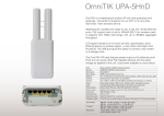
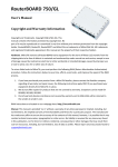
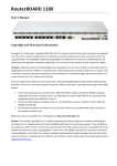
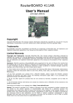
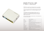
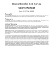
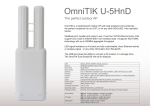
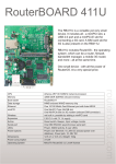
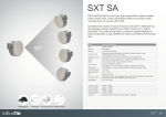
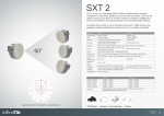
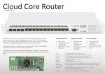
RouterBOARD SXT 5HnD
User's Manual
(Rev.6; 27-Jan-2011)
Copyright
Copyright MikroTikls SIA. This manual contains information
protected by copyright law. No part of it may be reproduced or
transmitted in any form without prior written permission from the
copyright holder.
Trademarks
RouterBOARD, RouterOS, RouterBOOT and MikroTik are trademarks
of MikroTikls SIA. All trademarks and registered trademarks
appearing in this manual are the property of their respective
holders.
Limited Warranty
Copyright and Trademarks. Copyright MikroTikls SIA. This manual contains information protected by
copyright law. No part of it may be reproduced or transmitted in any form without prior written permission
from the copyright holder. RouterBOARD, RouterOS, RouterBOOT and MikroTik are trademarks of MikroTikls
SIA. All trademarks and registered trademarks appearing in this manual are the property of their respective
holders.
Hardware. MikroTik warrants all RouterBOARD series equipment for the term of fifteen (15) months from the
shipping date to be free of defects in materials and workmanship under normal use and service, except in
case of damage caused by mechanical, electrical or other accidental or intended damages caused by
improper use or due to wind, rain, fire or other acts of nature.
To return failed units to MikroTik, you must perform the following RMA (Return Merchandise Authorization)
procedure. Follow the instructions below to save time, efforts, avoid costs, and improve the speed of the
RMA process.
1.If you have purchased your product from a MikroTik Reseller, please contact the Reseller company
regarding all warranty and repair issues, the following instructions apply ONLY if you purchased your
equipment directly from MikroTik in Latvia.
2. We do not offer repairs for products that are not covered by warranty. Exceptions can be made for
RB1000 and RB1100.
3. Out-of-warranty devices and devices not covered by warranty sent to Mikrotikls will be returned to the
sender at sender's cost.
Instructions are located on our webpage here: http://rma.mikrotik.com
Manual. This manual is provided “as is” without a warranty of any kind, expressed or implied, including, but
not limited to, the implied warranty of merchantability and fitness for a particular purpose. The manufacturer
has made every effort to ensure the accuracy of the contents of this manual, however, it is possible that it
may contain technical inaccuracies, typographical or other errors. No liability is assumed for any inaccuracy
found in this publication, nor for direct or indirect, incidental, consequential or other damages that may
result from such an inaccuracy, including, but not limited to, loss of data or profits. Please report any
inaccuracies found to [email protected].
RouterBOARD SXT Series User's Manual rev. 6
Table of Contents
Copyright....................................................................................................................................... 1
Trademarks.................................................................................................................................... 1
Limited Warranty............................................................................................................................. 1
System Board View......................................................................................................................... 3
System Board Layout....................................................................................................................... 3
Specifications................................................................................................................................. 4
Hardware Guide.............................................................................................................................. 4
LAN1 Port with PoE................................................................................................................. 4
LEDs..................................................................................................................................... 4
Onboard 802.11a/n 5GHz wireless............................................................................................ 5
Built in antenna...................................................................................................................... 5
USB port............................................................................................................................... 5
User's Guide................................................................................................................................... 6
First use................................................................................................................................ 6
Grounding............................................................................................................................. 6
Powering............................................................................................................................... 6
Mounting............................................................................................................................... 6
Booting options...................................................................................................................... 7
Onboard NAND Storage Device................................................................................................. 7
Booting from network.............................................................................................................. 7
RouterBOOT........................................................................................................................... 8
Boot Loader Configuration........................................................................................................ 8
Boot Loader Upgrading............................................................................................................ 8
Operating System Support....................................................................................................... 8
Connector Index..................................................................................................................... 8
Button Index.......................................................................................................................... 9
Ethernet Cables...................................................................................................................... 9
Federal Communication Commission Interference Statement
(FCC ID: TV7SXT-5D).............................................................................................................. 9
2
RouterBOARD SXT Series User's Manual rev. 6
System Board View
System Board Layout
Chain 0
3
RouterBOARD SXT Series User's Manual rev. 6
Specifications
RouterBOARD SXT 5HnD
CPU
AR7241 400MHz
Memory
32MB DDR SDRAM
Boot loader
RouterBOOT
Data storage
64MB onboard NAND memory chip
Ethernet
One 10/100 with Auto-MDI/X
Wireless
Built-in 5GHz 802.11a/n 2x2 MIMO
Antenna
Dual polarization 2x2 MIMO antenna
15kV ESD protection on each RF port
15kV ESD protection on the Ethernet port
ESD protection
MiniPCI slot
none
Serial port
none
LEDs
Power and User LED, 5 wireless LEDs
Extras
Beeper; Reset switch; USB 2.0 port; Voltage monitor; Temperature monitor
Power options
Dimensions
Weight
Temperature
Power consumption
RouterOS license
Power over Ethernet: 8..30V DC (except power over datalines)
Packaged with a 24V PSU and a PoE injector
140x140x56mm
265g
Operational: -30C to +80C
5W max
Level3
Hardware Guide
LAN1 Port with PoE
It is compatible with passive (non-standard) Power over Ethernet. The board accepts voltage input from 8 to
30 V DC. It is suggested to use higher voltages for power over long cables because of better efficiency (less
power is lost in the cable itself and power supply is more efficient).
See Connector Index for pinout of the standard cable required for PoE. All cables made to EIA/TIA 568A/B
cable specifications will work correctly with PoE. Note that this port supports automatic cross/straight cable
correction (Auto MDI/X), so you can use either straight or cross-over cable for connecting to other devices.
LEDs
•
Power LED is on when the board is powered. Open case door to see it.
•
User LED. Open door to see it. May be programmed at user's option. It is lit by default when the
board starts up, then it is turned off when the bootloader runs kernel. These RouterOS commands
turn it on/off: :led user-led=no ; :led user-led=yes
•
SXT-5D has 5 LEDs (LD1602..LD1606), which show wireless signal strength:
LD1602 - on, if wireless client is connected to AP (usually >= -89dBm)
LD1603 - on, if signal strength >= -82dBm
LD1604 - on, if signal strength >= -75dBm
LD1605 - on, if signal strength >= -68dBm
LD1606 - on, if signal strength >= -61dBm
It is possible to disable this function (turn all these LEDs off) via software configuration.
4
RouterBOARD SXT Series User's Manual rev. 6
Onboard 802.11a/n 5GHz wireless
This RouterBOARD model has a built-in 802.11a/n 5GHz wireless device based on the AR9280 Atheros
chipset. It doesn't support turbo mode.
There is no antenna connector, as the wireless part is directly connected to the built-in antenna.
Protocol
802.11a
802.11n
Protocol
802.11a
802.11n
Data rate
TX Power
6 Mbit/s
26dBm
54 Mbit/s
22dBm
MCS0/8 20MHZ
25dBm
MCS0/8 40MHZ
25dBm
MCS7/15 20MHZ
19dBm
MCS7/15 40MHZ
18dBm
Data rate
RX Sensitivity
6 Mbit/s
-96dBm
54 Mbit/s
-80dBm
MCS0/8 20MHZ
-96dBm
MCS0/8 40MHZ
-92dBm
MCS7/15 20MHZ
-77dBm
MCS7/15 40MHZ
-74dBm
Built in antenna
The SXT 5HnD has a built in dual polarization PCB type antenna:
Antenna
Type
Dual polarization 5GHz antenna
Frequency range
5.17 - 5.825 GHz
Gain
16 ± 2 dBi
VSWR, max
1.7:1
3 dB Beam-Width, H-Plane, typ. 25 °
3 dB Beam-Width, E-Plane, typ. 25 °
Polarization
Dual Linear (V-pol, H-pol)
Port to Port Isolation
- 35 dB
For single chain operation in V-pol, these options can be considered:
1.
leave everything as is, it will connect to Vpol devices by default if you didn't disable any chains in
RouterOS settings
2.
Turn antenna 90deg and use Chain0
3.
Don't turn antenna but disable Chain0-TX in RouterOS
USB port
The SXT has one USB 2.0 port. This port supports RouterOS USB power reset, a feature introduced to help
reboot 3G modems, but will reset any device connected to the USB port. It's available since RouterOS v4.14
/system resource usb power-reset
5
RouterBOARD SXT Series User's Manual rev. 6
The command disconnects power for USB port. However, the same power source is used for the Wireless
power amplifier. It means, that during USB power reset wireless signals are transmitted with reduced power.
It may cause small interruption of wireless communication.
User's Guide
First use
The SXT device is assembled and ready to use:
•
Plug the supplied PSU into a power socket, and connect it to the supplied PoE injector
•
Connect one end of the injector to a switch or any other device, and the other end to Ethernet cable
leading to the SXT device
•
Connect to the SXT device with SSH or Winbox to configure it. See this document for details:
http://wiki.mikrotik.com/wiki/Manual:First_time_startup
•
Configure RouterOS according to the manual:
http://wiki.mikrotik.com/wiki/Category:Manual
Configuration note: Wireless interface is disabled by default, you need to connect with any of the above
methods and enable and configure it. To use both chains, you need to enable HT TX/RX chains in the HT tab
in the RouterOS Wireless configuration.
Grounding
It is recommend to use a FTP (foil screened twisted pair) cable – in this case, one end of the cable would be
plugged into the SXT, the other end of the cable will be connected to the buildings grounding installation. If
possible, also connect a grounding wire to the provided grounding connection behind the SXT case door.
Powering
•
Power over Ethernet (PoE) on the Ethernet port:
8..30V DC (12..28 V suggested) non-standard PoE powering support. 24V PSU is supplied with the
device
RouterBOARD SXT series boards are compatible with non-standard (passive) Power over Ethernet injectors
(except power over datalines) and accept powering over up to 100m (330 ft) long Ethernet cable connected
to the Ethernet port (J4). The board does not work with IEEE802.3af compliant 48V power injectors.
Mounting
With the clip pointed forward, slide the mounting bracket onto the rail on the bottom of the case, until the
clip clicks into place. Make sure the clip is securely holding the mounting bracket in place.
The SXT comes bundled with a hose clamp - guide the clamp through the opening in the bracket and around
the pole where it will be mounted. Tighten the hose clamp screw when alignment is complete. Two screw
holes are provided as additional security against accidental bracket movement.
The SXT must be mounted with the door pointing downwards, to avoid moisture coming into the box. The
image shows the only correct way to mount the device. Small holes are located on the bottom to
provide ventilation and exit for condensate:
Top
Bottom
6
RouterBOARD SXT Series User's Manual rev. 6
The SXT device has a sliding door, behind which the Ethernet port, USB port, and the reset jumpers are
located. Also the User and Power LEDs become visible. When closing the door, make sure to click the latch
into place by applying medium amount of force. Make sure the door is tightly closed. This door can be also
secured shut with a screw in the provided screw hole. This is also protection against unwanted access to
your Ethernet port.
Second cable opening
If you would want to mount the SXT horizontally, you need to use the second cable opening, so that the
Ethernet cable goes straight down from that position. By default this opening is not accessible, you need to
use a drill or a sharp knife to open the second cable opening. The second cable opening could also be used
for grounding wire or USB cable.
Booting options
First, RouterBOOT loader is started. The loader may be configured to boot the system from the onboard
NAND module or from Ethernet network. See the respective section of this manual for how to configure
booting sequence and other boot loader parameters.
To reset RouterOS, or start booting from network, use the reset button. See Button Index
Onboard NAND Storage Device
The RouterBOARD may be started from the onboard NAND storage chip. As there is no partition table on the
device, the boot loader assumes the first 4MiB form a YAFFS filesystem, and executes the file called “kernel”
stored in the root directory on that partition.
Booting from network
Network boot works similarly to PXE or EtherBoot protocol, and allows you to boot a RouterBOARD SXT
series device from an executable image stored on a TFTP server. It uses BOOTP or DHCP (configurable in
boot loader) protocol to get a valid IP address, and TFTP protocol to download an executable (ELF) kernel
image combined with the initial RAM disk (inserted as an ELF section) to boot from (the TFTP server's IP
7
RouterBOARD SXT Series User's Manual rev. 6
address and the image name must be sent by the BOOTP/DHCP server).
To boot the RouterBOARD computer from Ethernet network you need the following:
● An ELF kernel image for the loader to boot from (you can embed the kernel parameters and initrd
image as ELF sections called kernparm and initrd respectively)
● A TFTP server which to download the image from
● A BOOTP/DHCP server (may be installed on the same machine as the TFTP server) to give an IP
address, TFTP server address and boot image name
See the Button Index section on how to configure loader to boot from network.
Note that you must connect the RouterBOARD you want to boot, and the BOOTP/DHCP and TFTP servers to
the same broadcast domain (ie., there must not be any routers between them).
RouterBOOT
The RouterBOOT firmware (also referred as “boot loader” here) provides minimal functionality to boot an
Operating System. RouterBOOT can be configured from the RouterOS “/system routerboard” menu. The
loader supports booting from the onboard NAND device and from a network server (see the respective
section for details on this protocol).
Boot Loader Configuration
As this device doesn't have a serial port, the Bootloader parameters may be configured through RouterOS
“/system routerboard” menu.
Boot Loader Upgrading
The boot loader is needed to initialize all the hardware and boot the system up. It's generally a good idea to
upgrade the loader once a newer RouterOS version is available.
The boot loader upgrading is supported from MikroTik RouterOS. Upload the FWF file to RouterOS files
menu, and run the “/system routerboard upgrade” command. Usually, RouterOS releases already include the
new Bootloader files in the routerboard.npk package, so if you have this package installed, you can check if
new Bootloader is available:
[admin@SXT] > system routerboard print
routerboard:
model:
serial-number:
current-firmware:
upgrade-firmware:
yes
"SXT"
"1FC201AD5C64"
"2.27"
"2.29"
[admin@SXT] >
As you see in the above example, new firmware is available. Type the following command to
upgrade it:
[admin@SXT] > system routerboard upgrade
Operating System Support
Currently tested operating system is MikroTik RouterOS (starting from version v4.16). Downgrading the
device to older RouterOS versions can cause malfunction and License issues.
Connector Index
J4
RJ45 Fast Ethernet 100Base-TX port LAN1 with passive PoE extension
1 Data TX+
2 Data TX3 Data RX+
8
RouterBOARD SXT Series User's Manual rev. 6
4 PoE power +
5 PoE power +
6 Data RX7 PoE power 8 PoE power -
9
RouterBOARD SXT Series User's Manual rev. 6
Button Index
S1400
RESET
This button has three functions. Hold the button, then apply power. Depending on when you
release the button, it will do these things:
•
release immediately (0-5 seconds) after starting the device to load backup bootloader
•
release when user LED starts to flash to reset RouterOS (5-10 seconds)
•
release after user LED stops flashing to start Etherboot (Netinstall) mode
(10+ seconds)
RouterOS reset jumper hole (RESET, marked with a black circle in the diagram above, below
S1400) – resets RouterOS software to defaults. Must short circuit the metallic sides of the
hole (with a screwdriver, for example) and boot the device. Hold screwdriver in place until
RouterOS configuration is cleared.
Ethernet Cables
RJ45
Pin
Color
Function RJ45 pin for Straight cable RJ45 pin for Crossover cable
(MDI, EIA/TIA568A)
(MDI-X, EIA/TIA568B)
1
Green
TX+ Data
1
3
2
Green/White
TX- Data
2
6
3
Orange
RX+ Data
3
1
4
Blue
-
4
4
5
Blue/White
-
5
5
6
2
6
Orange/White RX- Data
7
Brown
-
7
7
8
Brown/White
-
8
8
Federal Communication Commission Interference Statement
(FCC ID: TV7SXT-5D)
This equipment has been tested and found to comply with the limits for a Class B digital device, pursuant to
Part 15 of the FCC Rules. These limits are designed to provide reasonable protection against harmful
interference in a residential installation. This equipment generates, uses and can radiate radio frequency
energy and, if not installed and used in accordance with the instructions, may cause harmful interference to
radio communications. However, there is no guarantee that interference will not occur in a particular
installation. If this equipment does cause harmful interference to radio or television reception, which can be
determined by turning the equipment off and on, the user is encouraged to try to correct the interference by
one of the following measures:
●
●
●
●
Reorient or relocate the receiving antenna.
Increase the separation between the equipment and receiver.
Connect the equipment into an outlet on a circuit different from that to which the receiver is connected.
Consult the dealer or an experienced radio/TV technician for help.
FCC Caution: Any changes or modifications not expressly approved by the party responsible for compliance
could void the user’s authority to operate this equipment.
This device complies with Part 15 of the FCC Rules. Operation is subject to the following two conditions: (1)
This device may not cause harmful interference, and (2) this device must accept any interference received,
including interference that may cause undesired operation.
This device and its antenna must not be co-located or operation in conjunction with any other antenna or
transmitter. IMPORTANT: Exposure to Radio Frequency Radiation. 20 cm minimum distance has to be
maintained between the antenna and the occupational user and 45 cm to general public. Under such
configuration, the FCC radiation exposure limits set forth for an population/uncontrolled environment can be
satisfied.
10