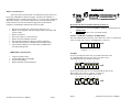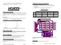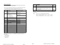
1
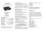
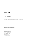
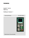
Technovision Interactive
TecCD USER MANUAL
Revision A
For additional sales information contact:
Technovision Sales
(905) 420-5153 extension 21
Visit our website to see what other innovative products are available:
www.technovision.com
MP3SA Industrial MP3 player with optional RS232 control.
PC2 multimedia controller.
V74BC button controller for Pioneer Industrial DVD players
and many more…
TECHNOVISION INTERACTIVE INC
1845 Sandstone Manor, Unit 2
Pickering, Ontario
L1W 3X9
CANADA
P: 905-420-5153
F: 905-420-0753
www.technovision.com
Page 2
Technovision TecCD User’s Manual
INSTRUCTIONS
What is a TecCD Player?
8 7 6 5 4 3 2 1
The TecCD from Technovision® is an industrial CD player based on a
heavy duty CDROM drive and power supply. It provides the capability of
AUTOMATICALLY repeating specific tracks (1..15) or the entire CD through
DIP switch settings. Users can also sample specific tracks through external
button selections. The TecCD can also be triggered by motion sensors,
computers or multimedia controllers like the PC2 or KPC1.
•
•
•
•
•
•
•
•
Dipswitch selectable disc or track repeat (Tracks 1 to 15).
Built in 5-watt amplifier with mono output (channel selectable) and
volume control.
Speaker connectors.
Stereo line output on 3.5mm connector.
RS232 control on a DB25F connector.
SR compatible with Pioneer PD-103 consumer CD player.
4x4 matrixed keypad port with DIPswitch selectable lockout.
Track indicator outputs (1x8 or 4x4 modes) with DIPswitch
selectable flashing mode.
-
LINE
ON
+
•
•
•
•
SR
1
DIP SWITCH
EXTERNAL CONTROL
Do not turn the unit on until the following has been set.
1.
2.
Attach the Line Audio Out (LINE) to amplifier or attach speaker to
Speaker Out.
DIPswitches must be set to your mode settings.
Switches 1-4 TRACK VALUE (0= ENTIRE DISC)
The first 4 DIPswitches set the track value. DIP 1 has a value of 1, DIP 2 has a
value of 2, DIP 3 has a value of 4 and DIP 4 has a value of 8.
ON ↓
VALUE
CDROM Drive Specifications:
8
8
4
2
1
Examples
If you are selecting the entire disc, you would set the track value
to 0. Meaning DIP 1 thru 4 are off, and if you want to keep
repeating this mode you set DIP6 on (repeat).
8 7 6 5 4 3 2 1
Long life brushless motor.
100,000 POH (Duty 20%) MTBF.
Powered tray loading.
Double shell dust-sealed mechanism.
ON ↓
If you need to repeat track 10, you would turn DIP 2(value 2) and
DIP 4(value 8) on. Value 2 + Value 8 = TRACK 10.
You would also have to turn DIP6 on for repeat.
8 7 6 5 4 3 2 1
ON ↓
VALUE
Technovision TecCD User’s Manual
Page 3
Page 4
8
2
Technovision TecCD User’s Manual
If you need to repeat track 15, you would turn DIP 4(value 8),
DIP 3(value 4), DIP 2(value 2) and DIP 1(value 1). Value
8+4+2+1=15.
8
7
6
5
4
3
2
EXTERNAL CONTROL Connector (DB25 female)
The EXTERNAL CONTROL connector has two main functions.
1. First function is to connect external push buttons. Refer to pushbutton
example below
2. Second function serves as the output for the track indicator.
1
ON ↓
VALUE
8
4
2
Push Button Example
Pins on EXTERNAL CONNECTOR
1
Switch 5 – INDICATOR MODE
With DIPswitch 5 OFF, the indicator mode for the track indicator is “linear” –
one output representing the track playing (1..8). With DIPswitch 5 ON, the
mode is set to “matrix” – a 4x4 configuration to represent the track playing
(1...16).
14
16
Track 1
2
Track 5
15
Track 9
Track 10
Track 11
Track 12
3
Track 13
Track 14
Track 15
Track 16
Linear Mode:
The TecCD has track indicators on the EXTERNAL CONTROL connector.
Switch 7 – FLASH MODE
There are 8 TTL outputs on the EXTERNAL CONTROL connector that
identify the current track that is playing. With DIPswitch 7 in the ON
position, the outputs will flash rather than remain on solid.
Track 6
TXD
RXD
5
Track 4
Track 7
Track 8
13
25
12
24
11
23
10
22
9
21
8
20
7
19
6
18
5
17
4
16
3
15
2
14
1
RS-232 Signals
TI3
TI2
TI1
TI0
VDD
VCC
VEE
D1
TI7
TI6
TI5
TI4
TI3
TI2
TI1
TI0
S3
S2
S1
S0
R3
R2
R1
R0
D2
330
TI4
D5
TI[0:7]
R1
R5
D9
R9
D6
D13
R13
D10
330
D7
R10
D14
R14
D8
330
D11
330
R8
330
D12
R11
330
D15
R4
330
R7
330
330
TI7
R6
D4
R3
330
330
TI6
D3
330
330
TI5
R2
R12
330
D16
R15
330
R16
330
S[0:3]
S3
S2
S1
S0
R[0:3]
DB25 Female
R0
B1
B2
B3
B4
R1
B5
B6
B7
B8
R2
B9
B10
B11
B12
R3
B13
B14
B15
B16
For Example: Button 1 (B1) will play track1 and would be connected to return
0 (R0) and scan 0 (S0). These are pins 14 and 16 on the DB25 female
connector.
Switch 8 – BUTTON LOCKOUT
With DIPswitch 8 in the ON position, subsequent button inputs will not
interrupt a button-activated track. A track that is repeating is not affected by
this setting.
Control (SR) in
External control connector for Pioneer’s SR Protocol.
Technovision TecCD User’s Manual
Page 6
Page 5
17
Track 3
TecCD Button/LED Indicator Diagram
Track Playing
5 volt output on pin (25ma)
1
6
2
19
3
7
4
20
5
8
6
21
7
9
8
22
Ground
10 and 18
See Button/LED Indicator Diagram for additional notes on Matrix Mode.
Switch 6 – REPEAT MODE
With DIPswitch 6 ON, the track designated by DIPswitches 1 to 4 will repeat
continuously. After the playing of a button activated track, the system will
continue repeating the track value specified.
4
Track 2
Technovision TecCD User’s Manual
RS232 Command Set
Commands are transmitted at 9600 baud, 8 bits, no parity and 1 stop bit
and is terminated with a carriage return.
The TecCD received the RS232 data on pin 23 and transmits data on pin
11 of the DB25 female connector. Data ground is pin 10 or 24.
Command
?
Dx
Kxx
NE
NT
PA
PG
PL
PT
P10
RE
RE0
RE1
RE2
ST
Txx
Description
Inquiry
Play Disc - conditional x
commands are:
x = R: Repeat disc
x = P: Play disc once
Play Key Track x
Prevent Medium Removal (No
Eject)
Next Track/Track Forward
Pause – cycles through modes
Program Mode
Play
Previous Track/Track Reverse
Plus Ten
Repeat (Toggle to next mode)
Repeat Off
Repeat Track
Repeat Disc
Stop
Play Track xx
Additional Comments
Responds with 4 bytes - see
Note 1 below
Version 3.4 Additions
PA0
Pause OFF
RS232
PA1
PA2
Pause (same as PA)
At the end of the current track, search back to the
beginning and pause. Sets the mode only – does not
pause the player
RS232
RS232
P
Play
RS232
Can now put the player into PAUSE mode when stopped. Kxx clears the
PAUSE flag.
Note 1:
SR & RS232
Bytes 1 & 2 are the dual digit track number.
Byte 3 is the repeat mode (0 = Off, 1 = Track, 2 = Disc).
Byte 4 is the play mode (0 = Stop, 1 = Play, 2 = Pause).
SR & RS232
SR & RS232
SR & RS232
SR & RS232
SR & RS232
SR & RS232
SR & RS232
SR & RS232
SR & RS232
RS232
RS232
RS232
SR & RS232
SR & RS232
Player responds with ‘R’<cr> to commands or sends an error code:
Error codes:
1…General Error
2…Out of range
3…Data Error
Technovision TecCD User’s Manual
Page 7
Page 8
Technovision TecCD User’s Manual