1
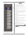
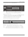
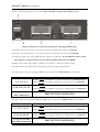
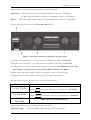
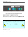
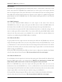
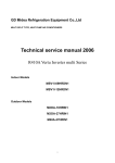
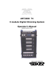
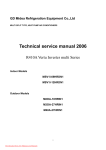
®
PEGASUS
PRO2
12-channel Digital Dimmer
User’s manual
Second edition
Copyright 2014
PEGASUS® PRO2 Digital Dimmer
Dear Customer!
Thank you for chose PLS Electronics product. If you have any technical question or you
looking for other equipments, don’t hesitate to take up the contact with our sales representative
or with the manufacturer at the www.pls.hu web site.
This apparatus is a twelve channel digital dimmer with DMX 512/1990 or 0-10V control
(optional) with additional control possibilities. The light control is produced by a phase angle
control technology.
Safety first! Please read carefully and understand the user manual!
The wrapper of the unit is NOT baby toy!
Keep it away form babies!
For technical questions and original spare parts
please take up the contact with our sales representative or with the
manufacturer at the www.pls.hu web site.
ATTENTION!
DON’T USE WITHOUT PROTECTIVE GROUND!
Not allowed to make a parallel connection between any outputs
(phases or neutrals) to increase the output current capability of the
unit! Otherwise the unit can be damaged!
CAUTION!
Do not cover any air inlets and fan outlets of the dimmer!
Take care to have proper airflow in and out to let cooling the unit.
CAUTION!
Disconnect mains before open the dimmer for service!
Service allowed only for technicians who had technical course by the sales
representative or by the manufacturer!
2
PLS Kft – www.pls.hu
Front parts
1 Phase / Module state indicators. If it’s ON, the
corresponding phase unit is working.
2. Circuit breakers to protect the outputs.
3. These green LEDs show the control level of each
channel.
4. These yellow LEDs show the output level of each
channel.
5. DMX control LED ( If it’s flashing, the DMX
pocket is correct; when OFF, the DMX pocket is
incorrect, not present or Analog control
(optional) is on.)
6. LCD display
7. ENTER button, use to enter to the menu, select
item and confirm the modification of the selected
parameter
8. ESCAPE button. Use to exit from the menu or
discard the modification of the selected
parameter
9. UP/DOWN buttons, use to scroll up/down on
the menu list or increase the value/level of the
selected parameter
10. DMX input via male XLR connector.
11. DMX throughput via female XLR connector
12. 120 Ohm DMX line termination switch. Switch
it to ON position only if this unit is the last on
the DMX line! Otherwise left it in OFF position!
Figure 1. Handling units of front part
3
PEGASUS® PRO2 Digital Dimmer
On Figure2 and Figure3 you can find the outlet of the backside connectors of the one output per
channel versions like Pro2-12xx-S (Schuko), Pro2-12xx-F (French/Belgian CEBEC),
Pro2-12xx-C (CEE16/3), Pro2-12xx-PC (PowerCon) and Pro2-12xx-WL (Wieland ST17)
dimmer
Figure 2. Back part connectors (Schuko, CEBEC, Swiss, Danish and UK BS1363)
Figure 3. Back part connectors (16A 3P CEE form)
1-12. Outputs of the channels from 1 to 12.
13. Mains input cable (H07 rubber; 5x6mm2 or 5x10mm2 ) without CEE male plug
14. Analogue input via 15 pole SUB-D male connector (optional). At -B suffixed version of the
Pro2 dimmer at this position you can find the XLR connectors for DMX!
15. Additional Protect Earth (PE) connection point for outputs with M4 nut
4
PLS Kft – www.pls.hu
Outlet of the backside connectors of the Pro2-12xx-H1 dimmer:
Figure 4. Back part connectors (24-pole ‘Harting/ILME’ type)
1. Outputs for the channels 1 to 12.
2. Analogue input via 15 pole SUB-D male connector (optional). At -B suffixed version of the
Pro2 dimmer at this position you can find the XLR connectors for DMX!
3. Mains input cable (H07 rubber; 5x6mm2 or 5x10mm2 ) without CEE male plug
4. Additional Protect Earth (PE) connection point for outputs with M4 nut
The pin outlet of 24-pole ‘Harting/ILME’ type connector is the follows:
Pin number
1-12
13-24
Side connectors
Function
Output phases for channel 1-12
Output neutrals for channel 1-12
PROTECTIVE EARTH (PE)
Recommended 24-pole male plug (optionally orderable form PLS):
Male insert: HDC HE 24 MT (Tension clamp, Weidmüller order no.: 1745850000)
or HDC HE 24 MS (Screw connection, Weidmüller order no.: 1211100000)
House:
HDC 24B TOBU 1M25G (M25 cable gland Weidmüller order no.: 1787820000)
or HDC 24B TOBU 1M32G (M32 cable gland Weidmüller order no.: 1787810000)
5
PEGASUS® PRO2 Digital Dimmer
Outlet of the backside connectors of the Pro2-12xx-H2 and Pro2-12xx-H2D dimmer:
Figure 5. Back part connectors (2x16-pole ‘Harting/ILME’ type)
1. Outputs for the channels 1 to 6. This connector referred in the future as SocketA.
2. Outputs for the channels 7 to 12. This connector referred in the future as SocketB.
3. Analogue input via 15 pole SUB-D male connector (optional). At -B suffixed version of the
Pro2 dimmer at this position you can find the XLR connectors for DMX!
4. Mains input cable (H07 rubber; 5x6mm2 or 5x10mm2 ) without CEE male plug
5. Additional Protect Earth (PE) connection point for outputs with M4 nut
The pin outlet of 16-pole ‘Harting/ILME’ type connectors in H2 version is the follows:
Pin number
1, 2, 3, 4, 5, 6
9, 10, 11 12, 13, 14
7, 8, 15, 16 and the
side connectors
Function
Output phases for channel 1,2,3,4,5,6 respectively on Socket-A and
output phases for channel 7,8,9,10,11,12 respectively on Socket-B.
Output neutrals for channel 1,2,3,4,5,6 respectively at Socket-B and
output neutrals for channel 7,8,9,10,11,12 respectively on Socket-B.
PROTECTIVE EARTH (PE)
The pin outlet of the 16-pole ‘Harting/ILME’ type connectors in H2D version is the follows:
Pin number
1, 3, 5, 7, 9, 11
2, 4, 6, 8, 10, 12
13, 14, 15, 16 and
the side connectors
6
Function
Output phases for channel 1,2,3,4,5,6 respectively on Socket-A and
output phases for channel 7,8,9,10,11,12 respectively on Socket-B.
Output neutrals for channel 1,2,3,4,5,6 respectively on Socket-A and
output neutrals for channel 7,8,9,10,11,12 respectively on Socket-B.
PROTECTIVE EARTH (PE)
PLS Kft – www.pls.hu
Recommended 16-pole male plug (optionally orderable form PLS):
Male insert: HDC HE 16 MT (Tension clamp, Weidmüller order no.: 1745840000)
or HDC HE 24 MS (Screw connection, Weidmüller order no.: 1207500000)
House:
HDC 16B TOBU 1M25G (M25 cable gland Weidmüller order no.: 1788210000)
Outlet of the backside connectors at Pro2-12xx-SX dimmer:
Figure 6. Back part connectors (2x19-pole ‘Socapex’ type)
1. Outputs for the channels 1 to 6. This connector referred in the future as Socket-A
2. Outputs for the channels 7 to 12. This connector referred in the future as Socket-B
3. Analogue input via 15 pole SUB-D male connector (optional). At -B suffixed version of the
Pro2 dimmer at this position you can find the XLR connectors for DMX!
4. Mains input cable (H07 rubber; 5x6mm2 or 5x10mm2 ) without CEE male plug
5. Additional Protect Earth (PE) connection point for outputs with M4 nut
The pin outlet of 19-pole ‘Socapex’ type connectors is the follows:
Pin number
1, 3, 5, 7, 9, 11
2, 4, 6, 8, 10, 12
13, 14, 15,
16,17,18,19
Function
Output phases for channel 1,2,3,4,5,6 respectively on Socket-A and
output phases for channel 7,8,9,10,11,12 respectively on Socket-B
Output neutrals for channel 1,2,3,4,5,6 respectively on Socket-A and
output neutrals for channel 7,8,9,10,11,12 respectively on Socket-B
PROTECTIVE EARTH (PE)
Recommended male plug (optionally orderable form PLS):
Male inline plug:
P19-LM-S-M40A (solderable, for cable OD 16-28mm)
7
PEGASUS® PRO2 Digital Dimmer
Outlet of the backside connectors at Pro2-12xx-STB dimmer:
Figure 7. Back part connectors (Screw terminal block input/outputs)
1. Outputs for the channels 1 to 6. Max wire cross section is 4mm2.
2. Outputs for the channels 7 to 12. Max wire cross section is 4mm2.
3. Analogue input via 15 pole SUB-D male connector (optional). At -B suffixed version of the
Pro2 dimmer at this position you can find the XLR connectors for DMX!
4. Mains input. Max wire cross section is 6mm2 (12x10A) or 10mm2 (12x13A and 12x16A)
CAUTION!
Installation of this dimmer version needs a trained service person.
Take extra care at the installation of the PE, Live and Neutral connections.
The Grey terminals always for LIVE (Line voltage)
Blue ones for the NEUTRAL
Green/Yellow ones for the Protect Earth!
Wrongly connected input mains or outputs can damage the dimmer and the loads!
2. Installation of the unit
After unpacking the apparatus is ready for use. Not to make the cable longer! If it is
short, use standard extension. Operating with injured cable is perilous!
8
PLS Kft – www.pls.hu
CAUTION!
The apparatus is NOT waterproof! Protect it from liquids!
Not to use outdoors without appropriate preventive measures.
If water or other liquid getting into it, dry up, and take to technician!
Working with wet apparatus is PERILOUS!
The unit has been shipped with 5x6mm2 (12x10A) or 5x10mm2 (12x13A and 12x16A) H07
rubber cable without CEE male plug (except screw terminal block type models). The correct
order of the power cable is the follows:
Cable color
Grey
Black
Brown
Blue
Green/Yellow
Function
Line 1 (L1 or R)
Line 2 (L2 or S)
Line 3 (L3 or T)
NEUTRAL (N)
Protect Earth (PE)
CAUTION!
The manufacturer doesn’t responsible if the installer/user connect the cable
wrongly! The guaranty will be void if the connection order is wrong and the
unit can damage too!
Before power up, always control the right connection of the Lines, Neutral
and the Protect Earth!
Consult with the manufacturer or
with trained service person if you need help in installation!
The unit is able to control 12x10A, 12x13A or 12x16A (depends on the dimmer model). The
input L1, L2 and L3 lines are connected to the channels as the follow:
1-4 channel to Phase L1; 5-8 channel to Phase L2; 9-12 channel to Phase L3
If necessary the dimmer can be powered from only one phase (L1, L2 and L3 inputs are
powered from the same phase). Please consider that in this case the maximum input power is
change like this:
- 12 x 10A model: 1 x 40Amps - 12 x 13A model: 1 x 52Amps - 12 x 16A model: 1 x 63Amps
These are the absolute maximum ratings!
If you overdrive, the dimmer can DAMAGE!
9
PEGASUS® PRO2 Digital Dimmer
3. Analog control (optional)
The functions of the SUB-D connector pins are in the following table:
Pin N°
1-12
13
14
15
Function
1-12 Channel IN
FIX +10V Output
(optional)
Analog mode enable input
(connect it to GND)
GND
The Pin 13 is an optional fix 10V (
IOMAX=50mA!) output. With this output and twelve
potmeters you can make a very simple control board to
this dimmer. The control board doesn’t need any other
power supply. Use 10K to 100K Linear type potmeters.
If you don’t want to use pin 13 leave it
UNCONNECTED! The pin 14 must be connected to GND to enable the analog control!
(Just connect the pin 14 to the pin 15.) While the analog control is enabled, the dimmer doesn’t
receive any data from the DMX line, and the display and the DMX LED are blank. For the
analog control cable use a 14 core wire with shield. The cable will be the shortest as possible. The
connector type is the SUB-D 15 pin female with house.
4. Digital Control
4.1 DMX input
The DMX input signal must be connect to the DMX In [11] marked connector, which can
be found on the front side of the unit. If this unit is the last one on the DMX network chain
you must take the termination switch on the front panel to “Term On” position on the font
panel. Otherwise left it at the other position!
Pin
Number
1
2
3
4
5
Function
Ground (Shield)
Data (-)
Data (+)
Spare Data (-) NC
Spare Data (+) NC
Table 1. Functions of XLR pins
Figure 5. Outlet of the connectors (front view,
the male connectors in the upper line)
The DMX input of the dimmer is power and opto isolated!
Not recommended to connect the Pin 1 to the Protect Earth (PE)!
The DMX Throughput is not isolated from the DMX input and not refreshed!
10
PLS Kft – www.pls.hu
4.2 Menu specification
After pressing the SET button on the dimmer you can reach the following menu points (use
UP/DOWN keys to scroll on the menu list)
1. Start Address
2. Test Outputs
3. Run Chaser
4. DMX Patch
5. Dimmer Curves
6. Dimmer Preheats
7. Dimmer MaxLevel
8. Memories
9. If DMX Fails
10. Factory Defaults
11. Dimmer Settings
To enter to the selected menu press the SET button again, otherwise press the ESC to go back
the standby display.
4.2.1. Start address set
In this menu point you can set the global start address of the dimmer (from the set address the
dimmer receives twelve DMX data and control the outputs from 1 to 12). Use the UP/DOWN
keys to change the address (from 001 to 512). To save the setting, press SET, otherwise press
ESC to go back into the menu list.
If the dimmer is in softpatch mode you have to disable it before you select global DMX address.
For it the dimmer ask back when you go into this menu point. To disable the softpatch, press
SET after this question displayed The factory default is 001.
4.2.2. Test the outputs of the dimmer
After entering this menu you have to select the testing way, blinking (the output blinks on/off
in each 1sec) or steady (the output in stable). Press SET for selection and now you can select
with UP/DOWN keys which channel you want to test (from 1 to 12). Press SET to modify the
light output level by the UP/DOWN keys; to choose another output press SET again. Press ESC
to exit from this menu.
11
PEGASUS® PRO2 Digital Dimmer
4.2.3. Chaser
The dimmer has 9 preprogrammed (non-modify able) scenes / chaser effects. After enter to this
menu, select with the UP/DOWN keys which chaser you want to play on the output. The first
three are fix light outputs (30%, 60% and 100%) for each channel; the last 6 are running chasers.
Press SET after selection and the chaser now present on the outputs. To modify the light level
(grand master) use the UP/DOWN keys. To select another chaser press SET, to exit from the
menu press ESC.
4.2.4. DMX Softpatch
You can select different DMX addresses for each output in this menu. First with the
UP/DOWN keys select the output, after press the SET and now select the DMX address for
that channel. Press the SET to chose another output and repeat the steps described before.
To exit from this menu press the ESC. Here the dimmer asks back, to enable this settings. If you
want to enable, press SET, otherwise ESC. If you choose SET, the global DMX address which
selected in the first menu point is now disabled. If you select ESC the selected addresses are
stored but not enabled (the global DMX address is enabled).
4.2.5. Dimmer PreHeat
To give preheat level for output enter into this menu point. With the UP/DOWN keys select the
output and after press SET. Now you can set the preheat level by the UP/DOWN keys. A star
(*) indicated next to the level that the data has been changed. Press SET and the level will be
stored into the memory and you can select another output or press ESC to exit from this menu
without saving you modification.
If you press ESC after pressing the SET (you don’t want to adjust more channels) the dimmer
stores the data and exit from the menu. The factory default is 0% for each output.
4.2.6. Dimmer MaxLevels
To set limitation for the output level, enter into this menu point. (Here actually the adjusted level
limits the DMX input value to the selected level.) DON’T use this feature to handle 115V
bulbs! Choose 120V control curve in the next menu point for those channels!
With the UP/DOWN keys select the output and after press SET. Now you can set the
maximum level by the UP/DOWN keys. A star (*) indicated next to the level that the data has
been changed. Press SET and the level will be stored into the memory and you can select another
output or press ESC to exit from this menu without saving you modification.
If you press ESC after pressing the SET (you don’t want to adjust more channels) the dimmer
stores the data and exit from the menu. The factory default is 100% for each output.
12
PLS Kft – www.pls.hu
4.2.7. Dimmer Curves
To select different control curves for each output, enter into this menu point. With the
UP/DOWN keys select the output and after press SET. Now you can set the control curve by
the UP/DOWN keys. A star (*) indicated next to the level that the data has been changed. Press
SET and the level will be stored into the memory and you can select another output or press
ESC to exit from this menu without saving you modification.
If you press ESC after pressing the SET (you don’t want to adjust more channels) the dimmer
stores the data and exit from the menu. The factory default is RMS Linear for each output.
4.2.8. Memories
Here you can play/record and edit dimmer scenes up to 16 memories. After enter with the
UP/DOWN keys select, which function you want to enter.
4.2.8.1. Play Memories
With the UP/DOWN keys select a memory what you want to play and press SET. With the
selected Fade In time the dimmer starts to fade (display) the memory. By pressing the ESC you
can fade back from the memory.
If the HTP is selected in the PRIORITY menu point (see three sections later) the dimmer
continues receiving DMX signal and handle the memory in Highest Takes Precedence priority.
Otherwise the DMX data receiving is disabled (but the LED on the front panel still indicate that
the DMX is present or not).
4.2.8.2. Edit Memories
With the UP/DOWN keys select the memory location what you want to edit and press SET.
After it the stored data is present on the outputs of the dimmer and you can edit it.
With the UP/DOWN keys select the output and press SET to change the value of that output.
Press the SET to store the set value or press ESC to exit without saving from this menu point.
Repeat the steps above to adjust the other channels if necessary.
If the selected memory location is not empty the dimmer prompt you that the location is
contain stored data. Press Ok to accept it and you overwrite the existing data or press
ESC to choose another location.
4.2.8.3. Record Memories
With this feature you can store DMX data into the memory.
Use the UP/DOWN keys to select memory location where you want to save the DMX input and
press SET.
13
PEGASUS® PRO2 Digital Dimmer
If the selected memory location is not empty the dimmer prompt you that the location is
contain stored data. Press Ok to accept it and you overwrite the existing data or press
ESC to choose another location.
4.2.8.4. Priority of Memories
If you want to add the DMX input data with the memory (at playing) chose with the
UP/DOWN keys the HTP (highest takes precedence). Otherwise select No DMX to disable the
DMX input while memory playing is in progress.
4.2.9. If DMX Fails
Here you can set how the dimmer react if the DMX signal is fails. You can choose from the
following possibilities:
1. Keep DMX value (the dimmer keep the output levels infinitely till a new valid DMX pocket
not arrive
2. Fade Out (with the selected wait and fade out time the dimmer fade back to zero level after
DMX data fails; you can set it in the Dimmer Settings menu section)
3. Play memory (The dimmer plays the selected memory location if the DMX fails. You can set
after pressing the SET button by the UP/DOWN keys. Press SET to store the selected memory
number and ESC to exit to the main menu.)
After change of these setting you have to restart the dimmer (disconnect-reconnect) to
have effect for the next DMX fail.
4.2.10. Factory defaults
To store back the factory settings you can choose from three alternatives by the UP/DOWN
keys:
1. Clear Settings (DMX addressing, softpatch, PreHeat and Maximum levels, Control curves)
2. Clear Mem (Clear only the stored memories, not modify the other settings)
3. Clear ALL (Clear the setting, the memories and set back the defaults for the dimmer settings
as well)
Press the SET at the chosen function or press ESC to exit from this menu point.
14
PLS Kft – www.pls.hu
4.2.11. Dimmer Settings
By pressing the SET button three times within two seconds you enter into the dimmer setting
menu point where you can adjust the following preferences:
1. User Control Curve
For each DMX input data (0-255) you can set output level (from 0%-100%) to give
freedom for special control cases.
2. If DMX Fails setup
Here you can select the Wait Time and the Fade Out time for the If DMX Fails menu
point.
3. Display Time
Here you can select the display backlighting time; the lighting time can be infinitely or can
be switch off after a specified time.
4. Memory Fade Times
Here you can specify the Fade In and Fade Out times for the memory play back.
Technical information
Power supply: ........................................................ TN-S 3x230V/400VAC ±10%
(3 x 40A or 3x 63A)
Power draw with open outputs:..........................10W
Output connectors:................................................ 12 x Schuko (-S), 2x 16-pole ‘Harting’ F (-H2);
2x 19-pole ‘Socapex (-SX), 12 x CEE16/3P (C)
12 x Neutrik PowerCon 16A (-PC)
Input connectors:..................................................15 pin SUB-D male (opt.) and 5 pole XLR male
Noise filters:...........................................................HF filters at all ch. (tr=225uS ±5% at 12x10A
model; tr=250uS ±5% at 12x13A and 12x16A
models)
Output protection:................................................C10A, C13A or C16A circuit breakers (1P, 1P+N
or 2P depends on the model)
Input protection: ...................................................TVS, opto and power isolation on DMX input
(the throughput is not isolated and refreshed!)
Operating temperature: ........................................10°C to 35°C (RH: 0-90%, non-condensing)
Storage temperature:.............................................-10°C to 60°C
Dimensions: ...........................................................484 x 132 x 350 + connectors
Weight:....................................................................18Kg
15
Declaration of Conformity
We, PLS Electronics Limited declare under sole responsibility that the product:
Product name: .......................................... Pegasus ® PRO2 12-channel dimmer series
Product model (output variations):............ S (Schuko), C (12 x 3 pole 16A CEE)
F (CEBEC), PC (12 x PowerCon)
H1 (24-pole ’Harting’), 2H1 (2x24-pole ’Harting’)
H2 (2 x 16-pole ’Harting’), 2H2 (4 x 16-pole ’Harting’),
SX (2 x 19-pole Socapex), 2SX (4 x 19-pole Socapex)
STB (Screw terminal blocks input/outputs)
Serial Number:......................................... n/a
Lot: .............................................................. n/a
Item number:............................................ One
to which this declaration relates is in conformity with the following standards:
•
EN 55015-1 (Electromagnetic compatibility. Limits and methods of measurement of
radio disturbance characteristics of electrical lighting and similar equipment (CISPR
15:2000+CISPR 15:2000/A1:2001+ CISPR 15:2000/A2:2003)
•
EN 61000-6-2 (Immunity for industrial environments)
•
EN 60439-1 (Low-voltage switchgear and controlgear assemblies. Part 1: Type-tested and
partially type-tested assemblies)
Therefore the upper indicated product qualifies the EU 73/23/EWG LV directive and the
89/33/EWG EMC directive, considering 93/465/EWG directive for CE.
Place of issue:
Szekesfehervar, HUNGARY
Signature of authorised person:
Date of issue:
01.03.2014
Sandor Vass
Managing Director of PLS Ltd
PLS Kft H-8000 Szekesfehervar, G zmalom utca 22. HUNGARY
Tel: +36-22-789-589 Fax: +36-22-382-783 E-Mail: [email protected]: www.pls.hu