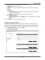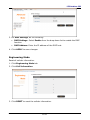
1
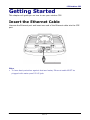
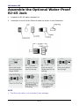
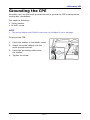
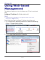
P/N: 65012500011 Rev.H EN-1 Table of Contents ABOUT THIS MANUAL............................................................................ 4 PRODUCT OVERVIEW .............................................................. 5 FEATURES ......................................................................................... 5 PACKAGE CONTENTS ............................................................................ 5 PARTS AND FUNCTIONS ......................................................................... 6 NOTICE BEFORE INSTALLATION ................................................................ 7 IMPORTANT INSTALLATION CONSIDERATIONS ............................................... 8 INSTALL THE SIM CARD....................................................................... 10 MOUNTING AND INSTALLATION .............................................................. 11 Mount Assembly package .................................................................. 11 Wall-mount Assembly ....................................................................... 12 Pole-mount Assembly ....................................................................... 13 GETTING STARTED ................................................................ 15 INSERT THE ETHERNET CABLE ............................................................... 15 ASSEMBLE THE OPTIONAL WATER-PROOF RJ-45 JACK .................................. 16 GROUNDING THE CPE ........................................................................ 17 CONNECT TO COMPUTERS .................................................................... 18 ADJUSTING CPE POSITION ................................................................... 19 Horizontal angle adjustment .............................................................. 19 Vertical angle adjustment ................................................................. 19 USING WEB-BASED MANAGEMENT ....................................... 20 CONFIGURE IP ADDRESS [FOR BRIDGE MODE ONLY]..................................... 20 LOGIN............................................................................................ 22 BASIC NETWORK SETTINGS .................................................................. 24 Configure Configure Configure Configure Mobile Internet Settings ..................................................... 24 CPE IP Settings ................................................................. 25 DHCP Services .................................................................. 26 CPE Time .......................................................................... 27 STATUS INFORMATION ........................................................................ 28 View Internet Connection Info ........................................................... 28 View CPE Info .................................................................................. 29 View Traffic Info ............................................................................... 29 SIM/PIN SETTINGS........................................................................... 30 Configure PIN .................................................................................. 30 Unlock SIM ...................................................................................... 31 SECURITY SETTINGS .......................................................................... 32 ADMINISTRATOR SETTINGS .................................................................. 33 Change Web Management Password .................................................. 33 EN-2 Enable Remote Access ...................................................................... 33 Manage LED Light ............................................................................ 34 Select Operation Mode ...................................................................... 34 ADVANCED DIAGNOSIS ....................................................................... 35 Enable SysLog ................................................................................. 35 View System Log ............................................................................. 36 Use Ping Test ................................................................................... 36 Use Traceroute Test ......................................................................... 36 SYSTEM MAINTENANCE ....................................................................... 37 Backup Configuration ....................................................................... 37 Restore Configuration ....................................................................... 37 Update APN ..................................................................................... 38 Restore Factory Defaults ................................................................... 38 Upgrade CPE Firmware ..................................................................... 38 NAT SETTINGS ................................................................................. 39 Configure Single Port Forwarding ....................................................... 39 Configure Port Range Forward ........................................................... 40 Configure Port Range Trigger ............................................................ 41 Enable UPnP .................................................................................... 42 Configure DMZ ................................................................................. 42 ENGINEERING MODE .......................................................................... 43 APPENDIX ............................................................................. 44 FAQ.............................................................................................. 44 TROUBLESHOOTING............................................................................ 45 SPECIFICATIONS ............................................................................... 46 SAFETY INFORMATION ......................................................................... 48 FEDERAL COMMUNICATION COMMISSION INTERFERENCE STATEMENT................. 49 EN-3 LTE Outdoor CPE About this Manual The content of this User Manual has been made as accurate as possible. However, due to continual product improvements, specifications and other information are subject to change without notice. EN-4 LTE Outdoor CPE Product Overview Congratulations on your purchase of this LTE outdoor CPE. With this LTE (Long Term Evolution) CPE (which is also known as 4G CPE), you can share high speed mobile broadband connectivity in a wide range of computing environment. Before you begin using the LTE outdoor CPE, read this chapter to familiarize yourself with the device. Features Embedded high gain directional antenna IP66 protection against dust and water Easy configuration based on Web Interface Provide 10 – 30dB more coverage gain compared to indoor CPE Support Passive Power over Ethernet. Easy installation and use Package Contents The following items come with your package. If any of them is damaged or missing, please contact your retailer. LTE Outdoor CPE Mounting bracket Optional: Plug head water resistant kits (RJ-45) Passive PoE adapter (48V, E500P series) Passive PoE adapter (12V, E500A series) NOTE The pictures are for reference only, actual items may slightly differ. EN-5 LTE Outdoor CPE Parts and Functions No. Item Description 1 Power Power LED will remain lit while power is applied. 2 Signal strength Indicate receive signal strength. The Signal Strength LEDs are only used at the power on to assist the installation. The CPE will turn off all the Signal Strength LEDs after a timer expires from power on. Such design is to prevent the outdoor CPE becoming a potential target particularly at night. The default time is 60 minutes however, is user settable in the web GUI. 3 Mount base Attach the mount bracket. 4 Earth ground terminal It is necessary to connect a grounding wire to protect the CPE from ESD (electrostatic discharges) and lightning. See “Grounding the CPE” on page 16 for more details. 5 Ethernet port Connect to a computer/ Passive PoE using an Ethernet cable. 6 Reset button Short press to restart the device. Long press for 5 seconds to reset the settings to the factory default settings. 7 SIM card slot Insert the SIM card. EN-6 LTE Outdoor CPE Notice before installation Choose a solid and safe place (Wall or Pole) for CPE installation 1. Choose the best location of the house and the orientation of the CPE to get the strongest signal reception from base station. 2. The ambient temperature for E500A and E500P series must be within: E500A series: -10°C to 55°C E500P series: -40°C to 55°C NOTE For optimum reception, there are a few things you should consider before installation. Please see “Important Installation Considerations” on page 8 for more details. Prepare two Ethernet cables Be sure that one of the cables used is an outdoor grade CAT 5e (or above) Ethernet cable type and the length of the cables are adequate to reach the location of the CPE and indoor PPoE are. Prepare wrenches Prepare two adjustable wrenches or four combination wrenches. (size: 13mm x 2, 8mm x 1, and 19mm x 1) Warning: 1. Do NOT start any traffic test (ex: throughput test and internet browsing) before the installer returns to the ground. 2. Do ground the CPE to provide protection from ESD (electrostatic discharges) and lightning. EN-7 LTE Outdoor CPE Important Installation Considerations Before installing the outdoor CPE, consider the appropriate location, clearance, and device orientation. Location and Cable wiring 1. Consult your Service Provider to find the best location and angle for getting the strongest signal from the base station. 2. Do a walking test around the house to find the best spot with the strongest signal if you don’t obtain related information from Service Provider. 3. Mount the CPE at the highest possible location with a clear view of the base station signal source. Buildings or other obstructions will affect the quality of the signal you receive. 4. Keep the best distance as possible from other devices that may cause interference. 5. Check if you can route the cable through the available ventilation holes to avoid unnecessary drilling and waterproofing the wall. 6. Disconnect the power cord first before mounting the CPE. Otherwise this may result in personal injury due to electric shock. EN-8 LTE Outdoor CPE Mounting 1. Choose a solid wall/ground to mount the CPE. 2. Mount on a wall/pole that can sustain the CPE dimensions and weight. 3. Mount upright on a vertical surface. Position Adjustment 1. The CPE must be directed towards the nearest base station. By pointing the CPE in the proper direction ensures that you receive the strongest signal. 2. Fine tune the signal by adjusting the orientation horizontally or vertically to increase the CPE signal strength. 3. To verify the signal strength level: Check the LEDs on the front panel - more lighted LEDs indicates stronger signal. Access the web management and go to Basic Mode > Status > Mobile Internet > Signal Quality to view the Rx signal strength. Warning: To receive stronger signal and to avoid possible RF radiation, please do NOT place your head or body in front of the CPE while you are positioning the CPE or checking the signal strength LEDs on the front panel. EN-9 LTE Outdoor CPE Install the SIM card This CPE is specially designed for the 4G LTE network. NOTE Check the availability of service and plan rates of data connections with your network service provider. 1. Unscrew the SIM card slot. 2. Insert a valid SIM card into the SIM card slot. Push it fully until it clicks into place. 3. Screw the cap back on tightly. Remove the SIM card Push to eject the SIM card from the slot. NOTE Once the SIM is reinserted, you must restart the CPE to read the SIM card properly. EN-10 LTE Outdoor CPE Mounting and Installation This CPE is weatherproof and designed for outdoor use. You can mount it to a wall or to a pole. Mount Assembly package NOTE The illustrations are for reference only, actual items may slightly differ. EN-11 LTE Outdoor CPE Wall-mount Assembly 1. 2. Align the mounting bracket on the wall. Using the bracket as mounting template, mark the positions to drill the holes. Assemble the bracket as shown in the illustration. 3. Attach the bracket to the back of the CPE. 4. Hang the CPE to the wall and secure the bracket using the designated screws and washers. EN-12 LTE Outdoor CPE Pole-mount Assembly To mount the CPE to a pole, follow the steps below: 1. Assemble the mounting bracket as shown in the illustration. 2. Attach the bracket to the back of the CPE. 3. Attach the bracket to the back of the CPE. EN-13 LTE Outdoor CPE 4. Align a pole on the bracket and assemble the pole bracket as shown. 5. Adjust the CPE position to an appropriate direction and secure the pole bracket using the designated screws and washers. EN-14 LTE Outdoor CPE Getting Started This chapter will guide you on how to use your outdoor CPE. Insert the Ethernet Cable Unscrew the Ethernet port and insert one end of the Ethernet cable into the CPE port. Note: To have best protection against dust and water, Ethernet cable MUST be plugged with water-proof RJ-45 jack. EN-15 LTE Outdoor CPE Assemble the Optional Water-Proof RJ-45 Jack 1. Unpack the RJ-45 water resistant kit. 2. Assemble one end of the Ethernet cable as shown in the illustration. NOTE The Ethernet cable is not included in the package. EN-16 LTE Outdoor CPE Grounding the CPE For safety use, use the earth ground terminal to ground the CPE housing before making any connections. You need the following: Spring washer M 4x8 L screw NOTE The spring washer and M4x8L screw are not included in your package. To ground the CPE: 1. Insert the washer to the M4x8L screw. 2. Attach the screw halfway into the earth ground terminal. 3. Insert the grounding cable under the washer. 4. Tighten the screw. EN-17 LTE Outdoor CPE Connect to Computers To use the Internet connection and configure the CPE settings, you must connect your CPE to a computer. Prepare two Ethernet cables for connection. 1. Insert the other end of the Ethernet cable to “P+D OUT” port of the PoE adapter. 2. Connect another Ethernet cable to a Network Hub/Router or directly to PC/Laptop via PoE adapter (“Data/IN” port). 3. Plug the PoE adapter to an electrical outlet. EN-18 LTE Outdoor CPE Adjusting CPE position To get a better reception, fine tune the CPE orientation (horizontally or vertically) to have the best signal strength shown from LED or other test equipment. Note: LEDs (on the front panel) indicate signal strength. Horizontal angle adjustment 1. Loose the top knob using the wrench as shown. 2. Swivel the device to the left or right to face the direction of the base station. 3. Secure the knob using the wrench after the position is fixed. Vertical angle adjustment 1. Loose the side knob using the wrench as shown. 2. Adjust the device position up or down to face the direction of the base station. 3. Secure the knob using the wrench after the position is fixed. EN-19 LTE Outdoor CPE Using Web-based Management This chapter will guide you on how to configure your CPE via the web-based utility. Configure IP address [for Bridge mode only] [Note] Configuring of the IP address is not required under router mode. Please go to “Login” directly. Please follow below steps to configure IP address under bridge mode. 1. Go to Control Panel>Network and Internet>Network and Sharing Center to Change adapter settings. 2. Click the Local Area Connection>Properties. EN-20 LTE Outdoor CPE 3. Choose Internet Protocol Version 4 (TCP/IPv4) then click Properties. 4. Enter the IP address as 192.168.168.X, Subnet mask as 255.255.255.0, and Default gateway as 192.168.168.168, Preferred DNS server from your ISP, then click OK. EN-21 LTE Outdoor CPE Login 1. Launch a web browser. 2. On the address bar, enter http://192.168.168.168, then press Enter. 3. On the opening screen, enter the username (admin) and password (admin) . 4. Click OK to login to the main screen. 5. Select preferred language, and click Apply. EN-22 LTE Outdoor CPE 6. Click one of the header tabs and click the left navigation submenu items to configure the system. Header categories Submenu items Submenu categories EN-23 LTE Outdoor CPE Basic Network Settings With Basic Mode, you can configure the basic settings of CPE and view CPE status. Configure Mobile Internet Settings Set up your 4G mobile broadband connection. 1. Click Basic Mode tab and select Network Settings. 2. Click Mobile Internet Settings. 3. Configure the APN setting. If there is a need for manual setting, enter the APN name, User Name and Password. 4. Click APPLY to save changes. NOTE If you are not sure of the details, contact your 4G internet service provider for more information. EN-24 LTE Outdoor CPE Configure CPE IP Settings Modify the IP address configuration of your CPE. 1. Click Basic Mode tab and select Network Settings. 2. Click CPE IP Settings. 3. Modify the necessary settings. IP Address: Enter the IP address of the CPE. By default, the IP address is 192.168.168.168. Subnet Mask: Display the mask used to divide the IP address. Device Name: Type a device name to use to access the web-based utility instead of entering the IP address on the address bar. In the case of the above illustration, you may type http://E500series.CPE on the address bar to access the web-based utility. 4. Click APPLY to save changes. EN-25 LTE Outdoor CPE Configure DHCP Services Configure your CPE to use the Dynamic Host Configuration Protocol (DHCP). With DHCP service, your CPE will automatically assign an IP address to each computer on your network. 1. Click Basic Mode tab and select Network Settings. 2. Click DHCP Services. 3. Modify the necessary settings. DHCP Server: Select to enable/disable the DHCP server. Start IP Address: Assign the first IP from the range to be leased. Maximum Number of Users: Enter the maximum number of IP addresses to be leased. Client Lease Time: Set the amount of time that the IP address will still be reserved for the computer after it has been disconnected from the CPE. 4. Click APPLY to save changes. EN-26 LTE Outdoor CPE Configure CPE Time Adjust the current system date and time. 1. Click Basic Mode tab and select Network Settings. 2. Click Time. 3. Modify the necessary settings. Current Time: Display the current date and time. Click SYNC WITH HOST to synchronize with the computer date and time. Time Zone: Select your local time zone from the list. 4. Click APPLY to save changes. EN-27 LTE Outdoor CPE Status Information View the CPE status information. View Internet Connection Info Display information on 4G status, 4G signal strength, network, and internet connection. 1. Click Basic Mode tab and select Status. 2. Click Mobile Internet. The following sections are shown: Signal Quality: Displays the Rx signal strength. U/SIM Status: Displays the SIM card status. Register Network: Displays the network information and status. Home/Roaming displays whether the network is in Home or Roaming mode. Internet Connection: Displays the Internet connection information, such as type, IP address, gateway, and DNS server. EN-28 LTE Outdoor CPE View CPE Info Display your CPE firmware version, local network settings, and DHCP client information. 1. Click Basic Mode tab and select Status. 2. Click CPE. View Traffic Info Display your CPE memory and network (WAN/LAN) data usage. 1. Click Basic Mode tab and select Status. 2. Click Traffic Usage. EN-29 LTE Outdoor CPE SIM/PIN Settings You can protect the 4G SIM card installed on your CPE from unauthorized users by requiring the PIN code or entering a password. Configure PIN Set the PIN code to enable SIM card lock. 1. Click Advanced Mode tab and select Mobile Internet Settings. 2. Click PIN Management. 3. Modify the necessary settings. U/SIM PIN Verification: Enter the PIN code. U/SIM PIN Management: Enable/Disable PIN protection after typing a PIN code and clicking APPLY. The PIN Protection field shows the state you want to change to. U/SIM’s Change PIN: Change the PIN code. 4. Click APPLY to save changes. EN-30 LTE Outdoor CPE Unlock SIM Unlock SIM is applicable only for other types of SIM to which the services are originally locked. When the SIM card is accessed and an invalid SIM is displayed on the screen, you must enter the SIM unlock password to unlock the SIM card. 1. Click Advanced Mode tab and select Mobile Internet Settings. 2. Click SIM Management. 3. Enter the password. 4. Click UNLOCK to unlock the SIM card. NOTE If you are not sure of the details, contact your 4G internet service provider for more information. EN-31 LTE Outdoor CPE Security Settings Configure firewall settings to suit your requirement. 1. Click Advanced Mode tab and select Security. 2. Click Firewall. 3. Modify the necessary settings. Ping from WAN Filter: Select to enable/disable Ping permit from WAN. If this function is enabled, you can remotely ping the network device from the WAN side. Block port scan: Port scanning means intruder across the network is scanning your computer for open ports possibly to see if there are any services running on your computer for hacking. Select whether to enable or disable the block port scan function. Block SYN Flood: SYN Flood is a common Denial of Service (DoS) attack in which an attacker sends a succession or flood of SYN packets. Select whether to enable or disable the block SYN flood function. SPI Firewall: SPI (Stateful Packet Inspection) Firewall filters more kinds of attacks by closely examining packet data structures. Select whether to enable or disable the SPI Firewall function. 4. Click APPLY to save changes. EN-32 LTE Outdoor CPE Administrator Settings Change the administrator password, configure remote access setting, set the timer duration for LED light, and select the operation mode of your CPE. Change Web Management Password Change the administrator password. 1. Click Advanced Mode tab and select Admin. 2. Click Management. 3. On Administrator Settings, do the following: Password: Enter the new password. Confirm Password: Enter again the new password for confirmation. 4. Click APPLY to save changes. Enable Remote Access Configure remote access settings. 1. Click Advanced Mode tab and select Admin. 2. Click Management. EN-33 LTE Outdoor CPE 3. On Remote Access, select Enable from the drop-down list to enable remote management function. 4. Click APPLY to save changes. Manage Signal Strength LED Indication Duration Set the duration for the LED light to stay on. 1. Click Advanced Mode tab and select Admin. 2. Click Management. 3. On Signal Strength LED Indication Duration, select the desired duration from the drop-down list. 4. Click APPLY to save changes. Select Operation Mode Set the operation mode of the CPE. 1. Click Advanced Mode tab and select Admin. 2. Click Management. 3. On Operation Mode, select one of the following options: Bridge: Select Bridge mode if you will have another router in your network to be set as the DHCP server. Clients in your network will directly receive IP address assigned by the server. After selecting Bridge mode, you may connect other routers or network devices. To access the CPE web-based utility in bridge mode, you must configure the IP address of the computer connected to the CPE with the IP address of the CPE. Router: Select Router mode to use the CPE as a router. 4. Click APPLY to save changes. EN-34 LTE Outdoor CPE Advanced Diagnosis Set the system log, view the system log entries, and configure Ping and Traceroute tests settings. Enable SysLog Configure the system log settings. 1. Click Advanced Mode tab and select Admin. 2. Click Diagnosis. EN-35 LTE Outdoor CPE 3. On Enable Syslog, do the following: Enable Syslog: Click Enable to enable the system log. Syslog IP: Specify the IP address of the server that will receive the system log. 4. Click APPLY to save changes. View System Log View the current system log entries. 1. Click Advanced Mode tab and select Admin. 2. Click Diagnosis. 3. On System Log, it displays the current system log entries. Click REFRESH to refresh the log shown on the screen. Click CLEAR to clear the current system log data. Use Ping Test Allow the CPE to ping the network devices to verify their connection. 1. Click Advanced Mode tab and select Admin. 2. Click Diagnosis. 3. On Ping test, do the following: IP or Address: Enter the IP address of the network device that you want to ping. Packet size: Enter the packet size. Number of Pings: Enter the number of pings. 4. Click APPLY to ping other network device. Use Traceroute Test Allow the CPE to trace the route that test packets take from one web destination to another. This function is commonly used to troubleshoot network problems and identify routing problems or firewalls that may be blocking access to a web site. 1. Click Advanced Mode tab and select Admin. 2. Click Diagnosis. 3. On Traceroute test, enter the IP or the domain name on IP or Address. 4. Click APPLY to monitor a network trace. EN-36 LTE Outdoor CPE System Maintenance Configure the settings to back up and restore the CPE configurations, upgrade the APN and CPE firmware, and reset the CPE to factory default settings. Backup Configuration Back up the CPE configuration to your computer. 1. Click Advanced Mode tab and select Admin. 2. Click Recover & Renewal. 3. On Backup, click EXPORT to export the current configurations to your computer. Restore Configuration Restore the previously saved backup of the CPE configuration. 1. Click Advanced Mode tab and select Admin. 2. Click Recover & Renewal. EN-37 LTE Outdoor CPE 3. On Restore, click the Browse button and select the previously saved configuration file in your computer. 4. Click IMPORT to update the CPE configuration. Update APN Update the APN database. 1. Click Advanced Mode tab and select Admin. 2. Click Recover & Renewal. 3. On APN Update, click START UPGRADE to update the APN. Restore Factory Defaults Reset your CPE to the factory default settings. 1. Click Advanced Mode tab and select Admin. 2. Click Recover & Renewal. 3. On Factory Defaults, click LOAD DEFAULT to reset all configuration parameters to the factory defaults settings. Upgrade CPE Firmware Update the firmware of your CPE. 1. Click Advanced Mode tab and select Admin. 2. Click Recover & Renewal. 3. On Firmware Upgrade, click the Browse button and select the latest firmware in your computer. 4. Click START UPGRADE to upgrade the CPE firmware. EN-38 LTE Outdoor CPE NAT Settings Configure the network address translation (NAT) settings of the CPE. Configure Single Port Forwarding Single Port Forward allows users on the Internet to access this server by using the WAN port address and the matched external port number. When users send these types of request to your WAN port IP address via the Internet, the CPE will forward those requests to the appropriate servers on your LAN. Configured single port forward settings are listed on the table at the bottom of the screen. 1. Click Advanced Mode tab and select NAT. 2. Click Single Port Forward. 3. To configure the port forwarding, do the following: Application: Enter a rule name. LAN IP: Enter the local network IP address of the system hosting the server. EN-39 LTE Outdoor CPE Port External: Enter the external port to be redirected to Internal port. Internal: Enter the port used by the device to receive data. Protocol: Select the protocol from the drop-down list. Single Port Forward Firewall enable or disable: Select Enable from the drop-down list to enable firewall. 4. Click APPLY to save the configuration rules. Configure Port Range Forward Port Range Forward allows users on the Internet to access this server by using the WAN port IP address and the pre-defined range of ports. When users send these types of request to your WAN port IP address via the Internet, the CPE will forward those requests to the appropriate servers on your LAN. Configured port range forward settings are listed on the table at the bottom of the screen. 1. Click Advanced Mode tab and select NAT. 2. Click Port Range Forward. EN-40 LTE Outdoor CPE 3. To configure the port forwarding, do the following: Application: Enter a rule name. LAN IP: Enter the local network IP address of the system hosting the server. WAN Port Port Range: Enter the start-port and end-port used by the public port from the WAN side. Protocol: Select the protocol from the drop-down list. Port Range Forward Enabled/Disabled: Select Enable from the drop-down list to enable firewall. 4. Click APPLY to save the configuration rules. Configure Port Range Trigger Port trigger allows the device to monitor firstly if traffic on certain ports of a computer is being triggered or being sent out; if so, the incoming traffic from the Internet on certain ports will be allowed to pass into the same computer. 1. Click Advanced Mode tab and select NAT. 2. Click Port Range Trigger. EN-41 LTE Outdoor CPE 3. To configure the settings, do the following: Application Application: Enter a rule name. Protocol: Select the trigger port protocol from the drop-down list. Triggered Range: Enter the start-port and end-port that will trigger the device to open ports for incoming data. Forwarded Range: Enter the start-port and end-port used by the public port from the WAN side. Port Range Trigger Enabled/Disabled: Select Enable from the drop-down list to enable firewall. 4. Click APPLY to save the configuration rules. Enable UPnP Universal Plug and Play (UPnP) allows automatic discovery and control of services available on the network from other devices without user intervention. 1. Click Advanced Mode tab and select NAT. 2. Click UPnP. 3. On UPnP, select Enable from the drop-down list to enable the UPnP feature. 4. Click APPLY to save changes. Configure DMZ A DMZ (Demilitarized Zone) sets a single computer, called a DMZ host, on your network to receive unrestricted incoming traffic from the Internet. 1. Click Advanced Mode tab and select NAT. 2. Click DMZ. EN-42 LTE Outdoor CPE 3. On DMZ Settings, do the following: DMZ Settings: Select Enable from the drop-down list to enable the DMZ function. DMZ Address: Enter the IP address of the DMZ host. 4. Click APPLY to save changes. Engineering Mode Reset all cellular information. 1. Click Engineering Mode tab. 2. Click Cell Information. 3. Click RESET to reset the cellular information. EN-43 LTE Outdoor CPE Appendix FAQ This chapter contains a list of frequently asked questions when you set up your CPE configuration. Q: What and how to find my computer IP address? A: IP address is the identifier for a computer or device on a TCP/IP network. Networks using the TCP/IP protocol route messages based on the IP address of the destination. The format of an IP address is a 32-bit numeric address written as four numbers separated by periods. Each number can be zero to 255. For example, 192.168.168.254 could be an IP address. To find your computer IP address, In Windows, click Start > Run to launch the Command program. Type “ipconfig”, then press the Enter button. Your computer IP address is listed on the IP Address. Q: What is Long Term Evolution (LTE)? A: LTE is a 4th generation (4G) mobile broadband standard and is the successor to the 3G technologies CDMA/GSM/UMTS. The service is typically much faster on both uplink/download speeds. Q: What is a firewall? A: A firewall is a set of related programs that protects the resources of a private network from users from other networks. Q: What is Network Address Translation (NAT)? A: Network Address Translation (NAT) is the process where a network device, usually a firewall, assigns a public address to a computer (or group of computers) inside a private network. Q: What is Universal Plug and Play (UPnP)? A: UPnP is an open networking architecture that consists of services, devices, and control points. The ultimate goal is to allow data communication among all UPnP devices regardless of media, operating system, programming language, and wired/wireless connection. EN-44 LTE Outdoor CPE Troubleshooting This chapter contains a list of common problems that you might experience when using your CPE, and techniques to try and overcome the problem. If you need additional help, contact your retailer. Problems I cannot acquire network connection. The Power LED did not light up when I plugged the adapter. I cannot access the web management page. I forgot my login username and/or password. Solutions Make sure that a 4G SIM card is properly inserted to the CPE. • Check if the Ethernet cable is properly connected. • If you are using a PoE adapter, make sure that the Ethernet cables are properly connected and the power adapter is plugged into an appropriate power source. 3. Ensure you obtained the correct Access Point Name (APN) supplied by the SIM card carrier. Make sure that the power adapter is connected to the CPE and plugged in to an appropriate power source. Use only the supplied power adapter. Check that the power source is receiving sufficient power. If the error persists, you may have a hardware problem. In this case, you should contact technical support. Make sure you are using the correct IP address of the CPE. Your computer and the CPE IP addresses must be on the same subnet for local network (LAN) access. You can check the subnet in use by the CPE on the Basic Network settings. If the operation mode is bridge mode, please follow the steps shown on page”EN-20” to configure IP address for using web GUI management. Press the Reset button for five seconds to reset the settings to the factory default settings. Access the web management page. You can now login with the factory default username and password “admin”. EN-45 LTE Outdoor CPE Specifications Features Specifications Cellular Connectivity and Data Speed Model E503 E503T E504 E507 E512 E513 E520 E538 E540 E525 LTE band Band 3 Band 3 Band 4 Band 7 Band 12 Band 17 Band 13 Band 20 Band 38 Band 40 - - - - - - - Band 25 Band 2 BC1 (1900) EVDO Band - DC-HSPA+ DL Peak Data Rate UL Peak Data Rate LTE Bandwidth Antenna Water Resistant Interface 850 100Mbps 50Mbps Up to 20 MHz supported (real allocation depents on LTE channel planning) Antenna Type Embedded high gain directional antenna Antenna Gain 10~13dB gain (depends on model type) RX Diversity Antenna Built-in design MIMO Downlink 2x2 SU-MIMO IP Code IP66 Ethernet Port RJ45 x 1 (with power riding on Ethernet cable) SIM Slot Yes USB 2.0 Micro USB 2.0 for debug purpose Reset Button Reset to factory default setting Signal strength indicators: LED x 5 LED Indicator Power indicator: LED x 1 LED light up timer: 5 min / 10 min / 30 min / 1 hour(default)/ Permanent open Multiple VPN pass-through (IPSec, PPTP, L2TP), Router Features Security Firewall Protection (Block Port Scan/Block SYN Flood/Filter Ping from WAN), SPI Firewall NAT-NAPT Single Port Forward, Port Range Forward, Port Range Trigger, DMZ, UPnP DHCP DHCP Server/Client Other features IPv4, TCP, UDP, ICMPv4, ARP, HTTP/HTTPs EN-46 LTE Outdoor CPE Features CPE Management Specifications CPE Operation Mode Two modes of operation: Bridge or Router mode Browser-based Browser supported: IE, Firefox, Safari, Chrome Administration GUI Browser-based Administration GUI English Multi-Language Support Remote Management Web Browser Interface Command Line HTTP Telnet, SSH Interface Passive Power over Power Input Yes, both 12V and 48V passive PoE input power Ethernet Support supported (PPoE) CPE power consumption Operation Temperature Environment Max 6.6 Watts when heater is off Max 23 Watts when heater is on -40oC to 65oC (-40oF to 149oF) ( Excluding Power adaptor) Power Adapter 0°C to 40°C (32°F to 104°F) Operation Temperature Storage Temperature -40°C to 70°C (-40°F to 158°F) Operating Humidity 10% to 80% (Non-Condensing) Storage Humidity 5% to 90% (Non-Condensing) Dimensions 423.5 (L) x 309.5 (W) x 104 (H) mm Weight 2kg Certification FCC, RoHS Specifications are subject to change without prior notice. EN-47 LTE Outdoor CPE Safety Information Read and understand all safety information. Failure to follow all instructions listed below may result in electric shock, fire and/or serious personal injury. Power Cord Protection Do not connect the power supply cord on elevated surfaces. Avoid any obstructions in its path and no heavy items should be placed on the cord. Protect the power cord from being walked on or pinched. Object Entry Never insert objects of any kind through the openings of the CPE, as they may touch dangerous voltage points that could result in a fire or electric shock. Operating Environment Do not mount the CPE near any heat sources such as radiators, heat registers, stoves, or other apparatus (including amplifiers) that produce heat. Accessories Use only accessories specified by the manufacturer. Cleaning Unplug the CPE from the power outlet before cleaning. Use only a dry cloth to clean the device. Servicing Never attempt to disassemble the CPE yourself. In the unlikely event that smoke, abnormal noise, or strange odor is present, immediately turn off the CPE. Refer all servicing to qualified service personnel. EN-48 LTE Outdoor CPE Federal Communication Commission Interference Statement This device complies with Part 15 of the FCC Rules. Operation is subject to the following two conditions: (1) This device may not cause harmful interference, and (2) this device must accept any interference received, including interference that may cause undesired operation. This equipment has been tested and found to comply with the limits for a Class B digital device, pursuant to Part 15 of the FCC Rules. These limits are designed to provide reasonable protection against harmful interference in a residential installation. This equipment generates, uses and can radiate radio frequency energy and, if not installed and used in accordance with the instructions, may cause harmful interference to radio communications. However, there is no guarantee that interference will not occur in a particular installation. If this equipment does cause harmful interference to radio or television reception, which can be determined by turning the equipment off and on, the user is encouraged to try to correct the interference by one of the following measures: Reorient or relocate the receiving antenna. Increase the separation between the equipment and receiver. Connect the equipment into an outlet on a circuit different from that to which the receiver is connected. Consult the dealer or an experienced radio/TV technician for help. FCC Caution: Any changes or modifications not expressly approved by the party responsible for compliance could void the user's authority to operate this equipment. This transmitter must not be co-located or operating in conjunction with any other antenna or transmitter. Radiation Exposure Statement: This equipment complies with FCC radiation exposure limits set forth for an uncontrolled environment. This equipment should be installed and operated with minimum distance 20cm between the radiator & your body. EN-49