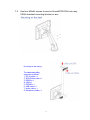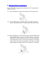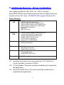
1
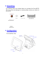
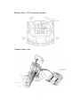
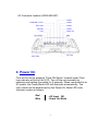
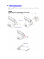
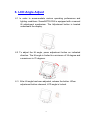
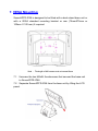
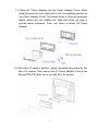
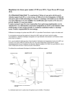
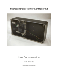
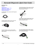
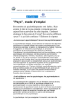
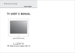
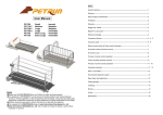
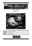
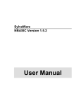
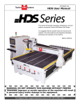
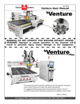
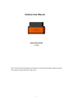
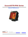
SxxxxADTR-IP66 Series
Quick Reference
i-Tech Company LLC
TOLL FREE: (888) 483-2418 • EMAIL: [email protected] • WEB: www.iTechLCD.com
1. Feature
SxxxxADTR-IP66 solid aluminum die-cast casing body maintains a strong,
compact look and utilizes innovative mechanism design to prevent dust, oil
and water from harsh environments. SxxxxADTR-IP66 fits perfectly to
hospitality, retail, finance and banking, travel and transportation, and selfservice kiosk.
Highlights:
■ Whole Unit IP66 Certification
■ Aluminum Casing
■ Fanless design
■ Removable Hard Disk
■ Wireless LAN
■ VESA Mount or Stand
■ Sub-Nano Coating
Applications:
■ Hospitality
■ Retail
■ Finance & Banking
■ Travel & Transportation
■ Self-service Kiosk
Note: Optional devices such as VESA standard mounting bracket or arm, Rotation
disk, Customer Display, Magnetic Card Reader, Smart Card Reader, I-Button,
Finger Print, RFID, and other I/O devices are available for optional choice.
1
2. Unpacking
The following items are included when you purchase the SxxxxADTRIP6. If any items are damaged or missing, please contact your dealer for
assistance.
Quick Reference
Antenna
(Optional Part)
3. Configuration
Front and Rear View
VFD Interface Cover
Antenna X^HDD
Cover
Push ON SwitchXT USB
Foot(5x)
2
Bottom View – I/O Connector Location
Chassis Inner View
3
I/O Connector Location (VESA MOUNT)
COM6
PRINTER or VGA
COM5
EXT USB
COM4
PS2 K/B
COM3
Audio Out
LAN
CF Card
EXT USB
4. Power On
Turn on the unit by pressing “Push ON Switch” located under iTech
logo indicator at front of the LCD. Turn off the unit manually by
pressing and holding the switch for 3 seconds. When connected to an
AC power, the Power Mode LED will illuminate automatically. The
unit’s mode can be determined by the Power On Mode LED color.
Indicator modes as follows:
Red
Blue
- AC Input OK
- Power On Mode
4
5. HDD Replacement
To remove HDD, use a screwdriver to loosen the screws on left side
of the panel.
Caution :
A. Hard Disk must be screwed into HDD Cover.
B. To install or to withdraw HDD, power must be switched off.
5
6. LCD Angle Adjust
6.1 In order to accommodate various operating preferences and
lighting conditions. SxxxxADTR-IP66 is equipped with a manual
tilt adjustment mechanism. The Adjustment button is located
underneath the display.
6.2 To adjust the tilt angle, press adjustment button as indicated
direction. The tilt angle is limited to a minimum of 34 degree and
a maximum to 70 degrees.
6.3 After tilt angle has been adjusted, release the button. When
adjustment button released, LCD angle is locked.
6
7. VESA Mounting
SxxxxADTR-IP66 is designed to be fitted with a desk stand base unit or
with a VESA standard mounting bracket or arm (75mmX75mm or
100mm X 100 mm) if required.
Note : The length of M4 screws must not exceed 8mm
7.1 Unscrew the two M4x8L thumbscrews that secured the base unit
to SxxxxADTR-IP66.
7.2 Separate SxxxxADTR-IP66 from the base unit by lifting the LCD
panel.
7
7.3 Place AC Power Adapter into the Power Adapter Cover. Place
silica gel grommet onto cable and fit into it’s matching position on
the Power Adapter Cover. The empty holes in silica gel grommets
where cables are not installed are fitted with Silica gel plug to
provide water resistance. Then, use Velcro to fasten AC Power
Adapter.
7.4 With each I/O cable in position, tighten the cable fixing panel by two
M3 x 15L screws. Then, secure the AC Power Adapter Cover to the
SxxxxADTR-IP66 back cover by eight M3 x 6L screws.
8
7.5
Use four M4x8L screws to secure SxxxxADTR-IP66 onto any
VESA standard mounting bracket or arm.
M ounting on the ceiling
The cable assembling
sequence as follows.
1. DC IN cable x 1
2. SCSI Printer cable x 1
3. RS232 x 4
4. LAN x 1
5. PS2/KB x 1
6. USB cable x 2
7. Audio cable x 1
8. Microphone cable x 1
9
8. Rotation Disk Installation
SxxxxADTR-IP66 is designed to be fitted with a 135° rotation disk to
enhance flexibility.
8.1 Use a screwdriver to remove the screws from five rubber feet.
8.2 Put I/O Cable through the rotation disk, then slide the rotation
disk into lock position. (Note: The table must have a 65mm hole)
8.3 Cable management is best achieved when the SxxxxADTR-IP66
is positioned above a hole on the table (65mm in diameter).
Cables will fall directly beneath the bench providing extra space.
If the table does not have a hole for the cables to run through,
rubber feet (5) will need to be replaced so that there is enough
space between the table and the unit for cables to run through.
10
9. Additional Devices : Driver Installation
After installing Win98 SE / ME / 2000 / XP / VISTA / Window 7,
SxxxxADTR-IP66 will need additional devices drivers installed which are
located in Driver CD. (Note : S150ADTR-IP66 supports Windows XP)
Driver CD menu
S150ADTRIP66
•
•
•
•
•
•
•
•
AMD GeodeLX Windows XP AES Driver
AMD PCI IDE Controller Driver
How to Install PCI IDE Controller Driver
AMD GeodeLX Windows XP Display Driver
AMD GeodeLX Windows XP Audio Driver
Driver Install Description
Dignostic
MB Linux Driver
S650ADTRIP66
•
•
•
•
•
•
Intel(R) Chipset Software Installation Utility
Intel(R) 945 GM/GSE Graphics Driver
Realtek High Definition Audio Driver
Realtek GbE PCI-E NIC Driver
PCI-E wireless LAN Driver
Observer 5.0.13(iSPOS650)
LAN Card
•
•
Realtek Network Interface Controller Drivers
Wireless LAN Driver
Document
•
•
•
•
•
•
iSPOS Series Document
KDS Series Document
iSMON Series Document
IC Card Reader
Touchscreen Driver
iTechLCD OPOS Driver
Tools
Testing Video •
IP66 Testing Video
9.1 Install the touch driver from enclosed driver CD. COM Port for
Touch Controller is located on COM 2.
9.2 IC Card Reader (The driver should be installed only if required by
the application).
9.3 iTechLCD OPOS Driver (The driver should be installed only if
required by the application).
11
Precaution
®
Specifications are subject to change without notice.
®
Avoid exposing the product to direct sunlight and do not use the product near
areas of high moisture.
®
Do not block the unit’s ventilation openings.
®
Do not attempt to disassemble or modify this product by yourself, as doing so
may expose you to an electric shock. All servicing should be performed by
qualified personnel and should conform to all local codes
®
SxxxxADTR-IP66 is equipped with the specific adapter (12V 5A). Do not use
any other type of adapter to operate the product. It is recommended that you
only use the manufacturer’s supplied adapter.
®
If any abnormal power conditions or blackouts occur during operation,
disconnect unit at the AC source immediately. Once normal power is restored,
reconnect the AC source.
®
To avoid unit failure or intermittent operation, check power and other I/O cables
are connected correctly.
®
Always unplug the power cord from the AC outlet before cleaning the product.
Use a soft cloth to clean the product. Do not use solvents or abrasives and do
not spray or pour any liquid directly onto the product’s screen or case.
12
i-Tech Company LLC
TOLL FREE: (888) 483-2418 • EMAIL: [email protected] • WEB: www.iTechLCD.com