1
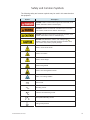
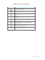
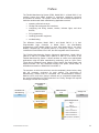
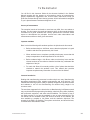
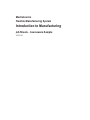
Mechatronics Flexible Manufacturing System Introduction to Manufacturing Job Sheets - Courseware Sample 38770-F0 Order no.: 38770-30 First Edition Revision level: 07/2015 By the staff of Festo Didactic © Festo Didactic Ltée/Ltd, Quebec, Canada 2007 Internet: www.festo-didactic.com e-mail: [email protected] Printed in Canada All rights reserved ISBN 978-2-89640-202-1 (Printed version) ISBN 978-2-89747-262-7 (CD-ROM) Legal Deposit – Bibliothèque et Archives nationales du Québec, 2007 Legal Deposit – Library and Archives Canada, 2007 The purchaser shall receive a single right of use which is non-exclusive, non-time-limited and limited geographically to use at the purchaser's site/location as follows. The purchaser shall be entitled to use the work to train his/her staff at the purchaser's site/location and shall also be entitled to use parts of the copyright material as the basis for the production of his/her own training documentation for the training of his/her staff at the purchaser's site/location with acknowledgement of source and to make copies for this purpose. In the case of schools/technical colleges, training centers, and universities, the right of use shall also include use by school and college students and trainees at the purchaser's site/location for teaching purposes. The right of use shall in all cases exclude the right to publish the copyright material or to make this available for use on intranet, Internet and LMS platforms and databases such as Moodle, which allow access by a wide variety of users, including those outside of the purchaser's site/location. Entitlement to other rights relating to reproductions, copies, adaptations, translations, microfilming and transfer to and storage and processing in electronic systems, no matter whether in whole or in part, shall require the prior consent of Festo Didactic GmbH & Co. KG. Information in this document is subject to change without notice and does not represent a commitment on the part of Festo Didactic. The Festo materials described in this document are furnished under a license agreement or a nondisclosure agreement. Festo Didactic recognizes product names as trademarks or registered trademarks of their respective holders. All other trademarks are the property of their respective owners. Other trademarks and trade names may be used in this document to refer to either the entity claiming the marks and names or their products. Festo Didactic disclaims any proprietary interest in trademarks and trade names other than its own. Safety and Common Symbols The following safety and common symbols may be used in this manual and on the equipment: Symbol Description DANGER indicates a hazard with a high level of risk which, if not avoided, will result in death or serious injury. WARNING indicates a hazard with a medium level of risk which, if not avoided, could result in death or serious injury. CAUTION indicates a hazard with a low level of risk which, if not avoided, could result in minor or moderate injury. CAUTION used without the Caution, risk of danger sign , indicates a hazard with a potentially hazardous situation which, if not avoided, may result in property damage. Caution, risk of electric shock Caution, hot surface Caution, risk of danger Caution, lifting hazard Caution, hand entanglement hazard Notice, non-ionizing radiation Direct current Alternating current Both direct and alternating current Three-phase alternating current Earth (ground) terminal © Festo Didactic 38770-30 III Safety and Common Symbols Symbol Description Protective conductor terminal Frame or chassis terminal Equipotentiality On (supply) Off (supply) Equipment protected throughout by double insulation or reinforced insulation In position of a bi-stable push control Out position of a bi-stable push control IV © Festo Didactic 38770-30 Table of Contents Preface ................................................................................................................. VII About This Manual ................................................................................................ IX To the Instructor .................................................................................................. XIII Job Sheet 1 Familiarization with the AC Drive ............................................. 1 Job Sheet 2 Ethernet Communication and PLC Programming Languages ................................................................................ 15 Job Sheet 3 Network Communications....................................................... 49 Job Sheet 4 PLC-Controlled Conveyor and Sensors ................................ 75 Job Sheet 5 Sorting Process ..................................................................... 101 Job Sheet 6 Filling Process ....................................................................... 113 Appendix A Equipment Utilization Chart .................................................. 133 Appendix B AC Drive – Quick Start Guide ............................................... 135 Appendix C Changing the PLC IP address setting.................................. 159 Appendix D Hydraulics and Pneumatics Graphic Symbols ................... 167 Appendix E Changing the node address of the DeviceNet devices ...... 169 Appendix F Safety Procedures ................................................................. 175 Appendix G Troubleshooting ..................................................................... 177 Appendix H PLC Programs ........................................................................ 181 Appendix I Fault Insertion ........................................................................ 229 © Festo Didactic 38770-30 V Preface The Flexible Manufacturing System (FMS), Model 5901-1 or Model 5901-3, is a modular system that allows students to experience challenges commonly encountered in facilities. The system comes with the necessary equipment to familiarize students with basic manufacturing applications such as: x operating a flat belt conveyor; x feeding and sorting parts into containers; x configuring and wiring sensors, buttons, indicator lights, and other devices; x PLC programming; x installing pneumatic equipment; x troubleshooting. The difference between Model 5901-1 and Model 5901-3 is in their Programmable Logic Controller. In Model 5901-1, the Allen-Bradley CompactLogix L32E (Model 5930-0) is used. With Model 5901-3, the AllenBradley CompactLogix L43 (Model 5930-A) is running the system. The L43 includes the functionalities of the L32E, but with integrated motion instructions. The Flexible Manufacturing System (Advanced Applications), Model 5901-2 (add-on to 5901-01) or Model 5901-4 (add-on to 5901-3), is an add-on to the Flexible Manufacturing System. It allows students to create more sophisticated applications using the latest manufacturing technology such as: Servo Drive, Touch-Screen Operated Control, Machine Vision System, Bar Code Reader, and Optical Encoder. The fully automated Storage Unit option, Model 5940, is available as an add-on to Model 5901-3 and 5901-4. The sequence in which the curriculum must be completed is shown below, along with the necessary equipment for each manual. The Introduction to Manufacturing manual must be completed first. Human-Machine Interface, Machine Vision, and Servo Control manuals can be completed independently, but are all prerequisites for FMS Production Line. Finally, Storage Unit requires knowledge of all the other subjects. Human-Machine Interface 85090 Introduction to Manufacturing Machine Vision FMS Production Line Storage Unit 38770 85091 85093 86694 86691 Servo Control 85092 86692 System Requirements 5901-1 or 5901-3 5901-1 and 5901-2 or 5901-3 and 5901-4 5901-1 and 5901-2 5901-3 and 5901-4 5901-3, 5901-4, and 5940 © Festo Didactic 38770-30 VII Preface We invite readers of this manual to send us their tips, feedback, and suggestions for improving the book. Please send these to [email protected]. The authors and Festo Didactic look forward to your comments. VIII © Festo Didactic 38770-30 About This Manual The Job Sheets in this manual are designed for students already familiar with electrical wiring, basic PLC programming, and manufacturing processes. These topics are thoroughly covered in the reference textbook provided with the Flexible Manufacturing System. A careful reading of the reference textbook is highly recommended before proceeding with the Job Sheets. The difficulty and complexity increase with each Job Sheet. First, the student familiarizes himself with the AC Drive and uses his wiring skills to build a small setup. Next, the student is introduced to PLC programming through four programs written in four different languages. These programs are used to control the push-button station. Each subsequent Job Sheet adds another level of complexity, allowing the student to acquire skills in advanced ladder diagram, structured text, sequential function chart, and block diagram programming. The student will also experience several situations encountered in manufacturing plants, including typical sensors applications, DeviceNet network configuration, quality control issues, and troubleshooting. For each Job Sheet, the required programs are provided on both the Flexible Manufacturing System Resource Kit (student) CD-ROM used the files corresponding to the right controller (L32E or L43). The latter includes complete solutions to the programming exercises proposed in the Job Sheets. Videos of some of the setups presented in the Job Sheets of this manual are also available on the CD-ROMs. a If the configuration files on the CD-ROM don’t have the same versions as the softwares, you can go to the following address: http://www.labvolt.com/downloads/download/FMS_CDROMs_Files.pdf. Safety considerations Safety symbols that may be used in this manual and on the equipment are listed in the Safety Symbols table at the beginning of the manual. Safety procedures related to the tasks that you will be asked to perform are indicated in each exercise. Make sure that you are wearing appropriate protective equipment when performing the tasks. You should never perform a task if you have any reason to think that a manipulation could be dangerous for you or your teammates. Reference textbook Stenerson, Jon. Fundamentals of Programmable Logic Controllers, Sensors, and Communications, 3rd ed. New Jersey: Prentice Hall, 2004. Flexible Manufacturing System Resource Kit CD-ROM Allen-Bradley/Rockwell Automation reference guides: x Programming Manual – Logix5000™ Controllers Common Procedures x Quick Start – Logix5000 Controllers x Quick Start – PowerFlex 40 Adjustable Frequency AC Drive © Festo Didactic 38770-30 IX About This Manual x Quick Start Manual – CompactLogix Controller Starter Kit x Reference Manual – Logix5000™ Controllers General Instructions x Technical Data – CompactBlock I/O for DeviceNet x User Manual – Adjustable Frequency AC Drive x User Manual – Compact™ I/O 1769-SDN DeviceNet Scanner Module x User Manual – CompactLogix Controllers x User Manual – DeviceNet Adapter x User Manual – DeviceNet Modules in Logix5000™ Control Systems Material: x PLC program files for each Job Sheet x Videos of the Flexible Manufacturing System in action Appendices Appendix A, Equipment Utilization Chart, indicates the components required to complete each of the Job Sheets in this manual. The chart also provides our part number for each component. Appendix B, AC Drive – Quick Start Guide, provides the information required to operate the AC Drive. Appendix C, Changing the PLC IP address setting, provides a step-by-step procedure to change the PLC IP address setting. Appendix D, Hydraulics and Pneumatics Graphic Symbols, lists common hydraulics and pneumatics graphic symbols. Appendix E, Changing the node address of the DeviceNet devices, provides a step-by-step procedure to change the DeviceNet node address of the AC Drive and Part Feeder. Appendix F, Safety Procedures, lists the basic safety procedures to be performed before you begin any of the Job Sheets in this manual. Appendix G, Troubleshooting, lists common problems that can be encountered when using the FMS and helps you to troubleshoot your setup. Appendix H (Instructor Guide only), PLC Programs, contains the listings of the instructor's version of the PLC programs. Appendix I (Instructor Guide only), Fault Insertion, lists all available faults. X © Festo Didactic 38770-30 About This Manual Systems of units Units are expressed using the International System of Units (SI) followed by the units expressed in the U.S. customary system of units (between parentheses). © Festo Didactic 38770-30 XI To the Instructor You will find in this Instructor Guide all the elements included in the Student Manual together with the answers to all questions, results of measurements, graphs, explanations, suggestions, and, in some cases, instructions to help you guide the students through their learning process. All the information that applies to you is placed between markers and appears in red. Accuracy of measurements The numerical results of the hands-on exercises may differ from one student to another. For this reason, the results and answers given in this manual should be considered as a guide. Students who correctly performed the exercises should expect to demonstrate the principles involved and make observations and measurements similar to those given as answers. Important reminders Bear in mind the following while students perform the job sheets in this manual: x Before students begin a Job Sheet, ensure that the equipment is in good condition and does not represent any risk if used. x When students have to complete a partially wired setup, ensure that this setup corresponds to the task requested in the Job Sheet. x Before students begin a Job Sheet, make sure that they have read the relevant sections of the reference material and that they understand the objectives of the job. x For each Job Sheet, this manual provides a list of points that should be checked to assess the students' work. This manual also provides important complementary information for some of the Job Sheets. Instructor introduction Dealing with manufacturing processes is neither simple nor easy. Manufacturing processes sometimes involve complex programming and tricky devices. The Flexible Manufacturing System (FMS) is specially designed to help both teachers and students to sail on the manufacturing sea without being caught in its numerous reefs. The exercises suggested in the Introduction to Manufacturing Job Sheets manual may require advanced programming knowledge, electrical wiring skills, familiarity with pneumatic equipment, and other technical abilities. The teacher is free to use each exercise as is or put the emphasis on one or more technical field. The Job Sheets can be modified to take into account the skills of the students, the time available to complete a Job Sheet, and the academic objectives. The strength of the FMS is its flexibility. The system can be bent, and should be bent, to the teacher's and students' needs. © Festo Didactic 38770-30 XIII To the Instructor Explore the Possibilities of the Flexible Manufacturing System From simple to complex The exercises in the Introduction to Manufacturing Job Sheets manual should be viewed as a whole. The difficulty and complexity of the exercises progressively increase from Job Sheet to Job Sheet. The students will need the knowledge and skills acquired previously to complete the Job Sheet at hand. The list below gives an overview of the Job Sheets' contents and shows how they are related to each other. Job Sheet 1 introduces the students to the basics of ac drives. The AC Drive is used in Job Sheets 3 to 6 to control the speed and direction of the Flat Belt Conveyor. Job Sheet 2 covers the fundamentals of PLC programming and gives an overview of the four programming languages used to program the PLC. The students are given the opportunity to compare the different programming languages by running four subroutines, each of them written in one of the four programming languages. Each subroutine controls the Emergency Switch Station and Indicator Light/Push-Button Station in the same way, the only thing that changes is the programming language used in the subroutine. Job Sheet 3 combines the equipment used in Job Sheet 1 and Job Sheet 2. The students use what they have learned in the first two Job Sheets to build a bigger setup. This setup is used to introduce the students to network communications. In the first part of this Job Sheet, the PLC communicates with the AC Drive through standard wires. In the second part of this Job Sheet, the PLC uses the DeviceNet network to communicate with the AC Drive. Job Sheet 4 adds two major elements to those already presented in the previous Job Sheets. Job Sheet 4 explains how sensors work and how to control the pneumatic equipment of the Flexible Manufacturing System. Make sure the students master the content of Job Sheets 1 to 3 before proceeding with Job Sheet 4. Job Sheet 4 is the core of the Introduction to Manufacturing Job Sheet manual. Job Sheet 5 increases the complexity of the pneumatics by adding the Pneumatic Sorting Device to the setup. This device is used to sort the metal boxes in three different trays when they reach the end of the Flat Belt Conveyor. Job Sheet 6 adds the final element to the setup progressively built in the first five Job Sheets. This last addition to the system is the Part Feeder. Once the Part Feeder is properly installed and configured, it can be controlled via its CompactBlock I/O module. With all the modules of the FMS in place, the students can simulate the main characteristics of an industrial production line. XIV © Festo Didactic 38770-30 To the Instructor The flexibility of the Flexible Manufacturing System The strength of industrial flexible manufacturing systems lies in their flexibility, and so it is with the Flexible Manufacturing System. The multifarious facets of the FMS are yours to explore. The following are some of the interesting features of the FMS: x The modules can be positioned anywhere on the perforated work surfaces, which allows easy and fast set up. x The type of wiring between modules can be chosen to suit your teaching objectives. Banana jack leads provide ease of setup while 24-gauge wires give the students an experience closer to what is found in the industry. Wiring ducts are provided with the system to maintain a tidy setup whichever type of wiring is opted for. Refer to the Use the Type of Wiring Suiting Your Teaching Objectives section below for details. x The sensors provided with the Flexible Manufacturing System can be interchanged to help the students to familiarize themselves with the various types of sensing devices used in industrial applications. The sensors (also called switches) used in the setups are usually wired as normally open switches. However, all switches can also be wired as normally closed switches. The figure below shows a sensor wired as a normally open switch and a sensor wired as a normally closed switch. The PLC programs and the wiring of the sensors can be modified to experiment further with sensors programming. + 24 V To a PLC input + 24 V To a PLC input a) Normally Open (NO or XIC) b) Normally Closed (NC or XIO). x The modules provided with the FMS are either fully configurable or have adjustments allowing calibration. Feel free to experiment with the modules, read the reference material, test the Job Sheets, and adapt the Job Sheets to your course curriculum. Create your own programs The programs provided with the Flexible Manufacturing System allow both the instructor and the students to get started quickly. They allow beginner students to learn the basics of flexible manufacturing without bothering with PLC programming. However, if you want to put the emphasis on the programming of flexible manufacturing systems, feel free to create your own programs or invite your students to do so. Designing and debugging PLC programs will challenge even advanced students. © Festo Didactic 38770-30 XV To the Instructor Programming exercises at the end of some of the Job Sheets suggest modifications to the PLC programs. The solutions to these exercises are given in the instructor's versions of the programs. The differences between the student's and the instructor's versions of the programs are identified by red boxes in the listing provided in Appendix H. a a The instructor's versions of the programs are available on the Flexible Manufacturing System Resource Kit (instructor) CD-ROM. All the configuration files for all the latest versions of the different softwares are available at the following address: http://www.labvolt.com/downloads/ download/FMS_CDROMs_Files.pdf. (The password for the instructor files for this manual is 38770). When designing or modifying programs, make sure to follow the equipment electrical requirements and the recommendations in the manufacturers' manuals. Use the Type of Wiring Suiting Your Teaching Objectives The Flexible Manufacturing System can be wired using either standard 24-gauge wires or banana-plug connection leads. Modules requiring wiring are equipped with both terminal blocks allowing the use of standard 24-gauge wires and colorcoded banana jacks. Pros and cons for both options are described below. Standard 24-gauge wires Using standard 24-gauge wires to wire the FMS allows the students to familiarize themselves with this type of electrical wiring. Furthermore, using standard wires gives a tidier setup since the length of the wires can be adjusted by cutting them to exactly what is required. Different wiring colors can be used to distinguish different classes of signals. On the other hand, wiring the entire system using standard 24-gauge wire can take a lot of time. Each wire must be cut to the appropriate length and the ends stripped. If the wires are not properly connected to the terminal blocks, beginner students can have a hard time trying to troubleshoot the system connections. Make sure to use the appropriate wire gauge. For 24 V dc signal wire, use 24 gauge wires. For details on the minimum requirements for power wires, refer to the manufacturer documentation provided on the Flexible Manufacturing System Resource Kit CD-ROM. Banana-plug connection leads Banana-plug connection leads are easy to use. No wire cutting or stripping is required. The banana jacks on the modules allow connections to be easily made without the use of a screwdriver. This reduces the set-up time and allows the students to concentrate on the connections instead of on the wiring. XVI © Festo Didactic 38770-30 To the Instructor However, banana-plug connection leads are available in certain lengths only. Because of this, the setup may be less tidy, thus harder to troubleshoot. Also, some of the banana-plug leads may be unplugged accidently by careless students. Wiring Ducts Whether using standard 24-gauge wires or banana-plug connection leads, the use of wiring ducts is recommended. Wiring ducts contain wires to keep them away from the modules and moving parts of the system. Before closing the wiring ducts, make sure all connections are correct. Troubleshooting Troubleshooting is an important part of the FMS training. To give the students a better idea of what is awaiting them in the industry, there is a Troubleshooting Exercise at the end of each Job Sheet. These troubleshooting exercises are designed to help the students to develop a structured method of troubleshooting the equipment used in the Flexible Manufacturing System setups. To complete successfully the Troubleshooting Exercises, the students must use their troubleshooting skills to identify the fault introduced in the system by the instructor. In the Job Sheet 1 to Job Sheet 6 sections, faults to insert or troubles to simulate are proposed. For a given Job Sheet, most of the proposed troubles or faults are related to newly introduced equipment. Tips to Speed Up Laboratory Sessions If required, the instructor can take special measures to shorten the time required to complete a Job Sheet. Follow the guidelines below if you need to shorten a laboratory session. x If a Job Sheet requires a great deal of wiring, a partially or completely wired setup can reduce the time required to complete it. x When a Job Sheet includes a Programming Exercise, the students are asked to make modifications to the PLC program. The Programming Exercise can be skipped if your course curriculum does not require students to acquire PLC programming skills. x At the end of each Job Sheet, there is a Troubleshooting Exercise. This Troubleshooting Exercise section is used to introduce the students gradually to FMS troubleshooting. The Troubleshooting Exercise can be skipped if time is running short. x The configuration of the Ethernet and DeviceNet networks can be tricky for students unfamiliar with computer networks. The configuring and testing of the network connections can be done by a technician instead of by the students. Configuring the Ethernet and DeviceNet networks will be much easier if the computer used to control the Flexible Manufacturing System is not connected to a local area network. If this is not possible, a computer with two network cards is required. © Festo Didactic 38770-30 XVII To the Instructor FMS Reference Material The Flexible Manufacturing System is provided with a wide variety of reference material to help the instructor planning the laboratory sessions. Important information can be found in the FMS reference material. Take the time to browse thoroughly through the reference material, this can save you time and effort. Textbook The Flexible Manufacturing System is provided with a reference textbook. This textbook covers most of the aspects of flexible manufacturing systems. It includes coverage of PLCs, programming, wiring, sensors, network communication, troubleshooting, and much more. Make sure the students have read the relevant chapters before they start working with the equipment. PLC programs The programs required to complete the Job Sheets are available on the Flexible Manufacturing System Resource Kit (student) CD-ROM. Each program includes comments to help students to find their way through the program code. An instructor's version of each program is available on the Flexible Manufacturing System Resource Kit (instructor) CD-ROM. The instructor's version of a program includes the solution to the Programming Exercise section. Videos The Flexible Manufacturing System Resource Kit CD-ROM also includes videos of the system in action. These videos show the final setup for some of the Job Sheets. They should give you a good idea of how the system should operate once the Job Sheet is completed. They also show how to perform particular operations and how some pieces of equipment should be manipulated. PDF Files Some parts of the equipment provided with the Flexible Manufacturing System are not entirely manufactured (as is the case with the PLC module). Important information on this equipment is provided in the PDF files available on the Flexible Manufacturing System Resource Kit CD-ROM. If you have problems using the equipment and you cannot find the solution in the documentation, refer to these files. Most of them provide a complete description of the device, technical information, error codes, troubleshooting tips, etc. XVIII © Festo Didactic 38770-30 To the Instructor Since students will have to deal with this type of documentation when working in the industry, it is important that they become familiar with this type of file. Moreover, some of the PDF files contain valuable information about PLC programming and network communications. The students should have access to these files, so they should be copied on the computer used to control the Flexible Manufacturing System (see section below). Copying the Flexible Manufacturing System Resource Kit (student) CD-ROM on the computer The files on the Flexible Manufacturing System Resource Kit (student) CD-ROM should be copied on the computer used to control the Flexible Manufacturing System. It is strongly suggested to copy the files in a folder named after the student's name, especially if the students are asked to modify the programs or the DeviceNet configuration. © Festo Didactic 38770-30 XIX Sample Extracted from the Job Sheets Student and the Job Sheets Instructor Information Job Sheet 4 PLC-Controlled Conveyor and Sensors Sensors Sensors are the eyes and ears of the PLC. Usually sensors are divided in two large categories: contact and non-contact. Contact sensors require a physical contact with the target to be triggered while non-contact sensors can sense the target without touching it, as long as the target is within the sensing distance. Sensors used in the Flexible Manufacturing System are non-contact sensors. The different types of sensors used with the Flexible Manufacturing System are presented below. Inductive sensor Inductive sensors are designed to detect metal targets passing within their sensing distance. The inductive sensors provided with the Flexible Manufacturing System are identified as Inductive Proximity Switch, Model 6375-B. They are either mounted on a flexible support or on another device such as the Pneumatic Sorting Device. An inductive sensor generates a weak oscillating magnetic field at its end. When a metallic target enters the magnetic field, eddy currents are induced at the surface of the target, which results in a loss in the oscillation amplitude in the oscillator. In turn, this loss in the oscillation amplitude causes a voltage drop in the sensor circuit. This voltage drop triggers an "on" output signal. Inductive sensors are composed of four essential parts (Figure 4-1): x the coil, which generates the magnetic field; x the oscillator which provides the oscillatory signal to the coil; x the trigger circuit, which detects the energy drop in the oscillator circuit when a metallic target interacts with the sensor magnetic field; x the output circuit, which provides the on or off signal to whatever device is connected to sensor. Output circuit Coil Oscillator Trigger circuit Figure 4-1. Inductive sensor (courtesy of Allen-Bradley). © Festo Didactic 38770-30 75 Job Sheet 4 – PLC-Controlled Conveyor and Sensors Figure 4-2 shows the change in the oscillator response and the resulting output voltage as a metallic target approaches the sensor. Target position Oscillator response Output voltage Releasing level Operating level Output Off On Off Figure 4-2. Effect of the target on the oscillator response and output voltage of an inductive sensor (courtesy of Allen-Bradley). The sensing distance of an inductive sensor is influenced by numerous factors. The composition of the metallic target has a considerable influence on the sensing distance. Most inductive sensors are optimized to detect mild steal targets. If the target is made of another material, a correction factor must be applied to the sensing distance. Large targets may be detected from a greater distance than small targets. Round or irregularly shaped targets may reduce the sensing distance. Polarized retroreflective sensor Polarized retroreflective sensors are optical sensors. They detect objects without physical contact by sensing the change in the intensity of the light emitted by a known light source. The polarized retroreflective sensor provided with the Flexible Manufacturing System is mounted on a flexible support and is identified as Polarized Retroreflective Photoelectric Switch, Model 6374-B. 76 © Festo Didactic 38770-30 Job Sheet 4 – PLC-Controlled Conveyor and Sensors A polarized retroreflective sensor uses an LED (Light Emitting Diode) as a light source. The LED emits light within a narrow band of wavelengths (usually infrared), which is reflected by a special reflector. The reflected light is detected by a light detector installed in the same housing as the light source. If an object gets between the sensor and the reflector, the light beam is cut and the light detector senses the difference. The appropriate output signal is then generated by the output circuit. Since the light emitted by the sensor may also be reflected back to the light detector by shiny objects, the light emitted by the sensor is polarized by a polarizing filter placed in front of the sensor LED. The polarizing filter only allows the light having an electric field (thus a magnetic field) oscillating in a specific direction in the plane perpendicular to the direction of travel. Figure 4-3 shows non-polarized light (incoherent radiation) passing through a polarizing filter that allows only vertically polarized light to pass through. Polarizing filter Unpolarized light Polarized light Figure 4-3. Polarizing filter allowing only vertically polarized light to pass through. If a polarizing filter allowing only horizontally polarized light to pass through is placed in front of a vertically polarized light beam, what will get through? Nothing, since vertically polarized light has no horizontal component. This is the secret behind the polarized retroreflective sensors. A polarizing filter is placed in front of the light source and another filter, perpendicular to the light source one, is placed in front of the light detector (receiver). Thus, if the light from the light source is reflected by a shiny object, nothing is detected by the detector. But, if the light bounces on the special reflector, the light is depolarized and the receiver can detect a portion of the reflected light. Figure 4-4 shows how a polarized retroreflective sensor works. © Festo Didactic 38770-30 77 Job Sheet 4 – PLC-Controlled Conveyor and Sensors Object to be sensed Retroreflective target Sensor Figure 4-4. Target detection with a polarized retroreflective sensor (courtesy of Allen-Bradley). 78 © Festo Didactic 38770-30 Job Sheet 4 – PLC-Controlled Conveyor and Sensors Emitter Polarizing filters Polarized light Lens Receiver Polarized light Depolarizing Retroreflector Depolarized light Emitter Polarized light Receiver The receiver does not receive light (target detected) Shiny target Polarized light Figure 4-5. Even shiny objects can be detected by a polarized retroreflective sensor. © Festo Didactic 38770-30 79 Job Sheet 4 – PLC-Controlled Conveyor and Sensors Background-suppression diffuse sensor Background-suppression diffuse sensors are also optical sensors but, unlike retroreflective sensors, they do not require a reflector. The backgroundsuppression diffuse sensor provided with the Flexible Manufacturing System is mounted on a flexible support and identified as a Background Suppression Photoelectric Switch, Model 6373-B. A background-suppression diffuse sensor uses an LED as a light source. When an object passes in front of the sensor, the light from the LED is scattered and a small portion of this light is detected by the light detector which is in the same housing as the light source (Figure 4-6). Sensor Object to be sensed Figure 4-6. Target detection with a diffuse sensor (courtesy of Allen-Bradley). To avoid confusing the background behind the target with the target itself, special electronics suppress the background and allow objects to be detected even when the background is reflective. Capacitive sensor Capacitive sensors use a change in capacitance to detect a target passing within the sensing distance. The capacitive sensors provided with the Flexible Manufacturing System are mounted on the Part Feeder hoppers. A capacitive sensor generates a weak electrostatic field at its end. The sensor oscillator stays inactive unless the target enters the electrostatic field. When a target passes within sensing distance, an electric field is generated between the sensor and the target and the oscillator starts to oscillate. When it does, the amplitude of the oscillations in the circuit increases and so does the voltage in the oscillator. This voltage change triggers an "on" output signal. Capacitive sensors are composed of four essential parts (Figure 4-7): 80 x the coil, which generates the electrostatic field; x the oscillator, which stays inactive unless a target interacts with the electrostatic fields; x the rectifier circuit, which rectifies the signal from the oscillator; x the output circuit, which provides the on or off signal to whatever device is connected to sensor. © Festo Didactic 38770-30 Job Sheet 4 – PLC-Controlled Conveyor and Sensors Output circuit Probe Oscillator Rectifier filter Figure 4-7. Capacitive sensor (courtesy of Allen-Bradley). Sensors wiring The sensors mounted on flexible supports can be wired either as normally open or normally closed switches. Make sure to check the wiring diagram in each Job Sheet to wire the sensors correctly. Pneumatics Modern assembly lines are nearly impossible to imagine without pneumatics. Sometimes it is the easiest and most efficient way to convert energy into actual work. Pneumatics is thus an unavoidable topic when flexible manufacturing systems are discussed. The pneumatic circuits used in the Flexible Manufacturing System Job Sheets contain the following elements: a source of compressed air, a pressure control device, tubing, an actuator, and a directional control valve to control the operation of the actuator. The sections below describe how the pneumatic equipment provided with the Flexible Manufacturing System works. a The Flexible Manufacturing System must have an adequate supply of pressurized and relatively dry air. The compressed air can be obtained from an adequate compressed air supply located in the classroom or from an air compressor. The air supply must deliver at least 138 kPa (or 20 psi). Push-in Tube Fittings Flexible Manufacturing System components are equipped with push-in tube fittings that allow one to quickly assemble and disassemble pneumatic circuits. To connect tubing to a fitting, simply push the tubing in as far as it will go. To disconnect the tubing, grasp the tubing near the fitting and push the tubing and collar of the fitting in toward the component. Hold down the collar in one hand, and pull the tubing out with the other hand. The ends of the tubing will wear out with repeated use. Eventually, the tubing will not seal properly in the fittings. When this happens, the worn tubing end must be trimmed. Use a tube cutter to remove about 12 mm (or 1/2 in) of the worn tubing. © Festo Didactic 38770-30 81 Job Sheet 4 – PLC-Controlled Conveyor and Sensors Pneumatic cylinders Some of the applications presented in this Job Sheet and in the following Job Sheets require that pneumatic cylinders extend and retract automatically. This is called cylinder reciprocation. Cylinder reciprocation involves a change in direction of the cylinder. Automatic reversal is achieved using the Directional Control Valve Station. The shifts of the four directional valves of the station are triggered with signals from the PLC. This allows extension or retraction of the cylinders according to the information provided by the sensors and other devices. Figure 4-8 below illustrates the flow of air through a simple pneumatic circuit, similar to those used in the Flexible Manufacturing System. Compressed air from either an air compressor or a pressurized air supply is sent to the Conditioning Unit which controls the air pressure in the circuit. From the Conditioning Unit, air goes through a Safety Valve which will purge the system if the electrical power is lost at the valve solenoid. From the Safety Valve, air passes through tubing and is directed to the desired branch of the circuit by a control valve. This extends or retracts the cylinder depending to which branch the air flow has been redirected. Conditioning unit Cylinder Compressed-air source Safety valve Directional control valve station Figure 4-8. Fundamental flow circuit. Conditioning Unit The Conditioning Unit consists of a main shutoff valve, a pressure regulator, a Directional Valve, a filter, an outlet port, and a muffler as shown in Figure 4-9. 82 © Festo Didactic 38770-30 Job Sheet 4 – PLC-Controlled Conveyor and Sensors Pressure Regulator Regulated pressure gauge Main shutoff valve Outlet port Main shutoff valve Air inlet Filter Muffler Filter regulator (simplified symbol) Figure 4-9. Conditioning Unit and Components. x Main Shutoff Valve The main shutoff valve opens and closes the air supply line between the air supply and the circuit. The air supply line is on when the button is in the upper position and is off when the button is in the lower position. When the button is in the off position, the pressure in the regulator is exhausted to the atmosphere. x Pressure Regulator Pressure regulators are used to limit and to maintain a constant pressure in a circuit. They allow an operator to manually set the pressure in the circuit downstream from the valve. The operation of a simple pressure regulator is illustrated in Figure 4-10. Air flows through the valve by entering the inlet port and leaving through the outlet port. The spring exerts a downward force against the top of the diaphragm, holding the poppet out of the way. An internal pilot passage allows pressure to exert an upward force underneath the diaphragm. Full system flow will pass through this valve as long as the poppet is not blocking the way. When the pressure increases at the outlet port, the pressure works against the spring and will move the poppet up, blocking the way to the inlet pressure. © Festo Didactic 38770-30 83 Job Sheet 4 – PLC-Controlled Conveyor and Sensors Adjustment screw Spring Diaphragm Inlet port Outlet port Pilot passage Light spring Symbol Poppet Figure 4-10. Pressure Regulator. a x Your Conditioning Unit is equipped with a Directional Valve, Double-Air-Pilot Operated indicating the pressure after the pressure regulator. We will refer to this meter as a regulated pressure gauge. Pressure Gauge Pneumatic pressure gauges measure the force applied by compressed air in pneumatic circuits. They allow operators to monitor the pressure in a system or in a branch circuit to ensure that the correct amount of work is being done and that pressure is not high enough to damage the components. Bourdon tube Gear mechanism Symbol Pointer indicator Pressure port Figure 4-11. Pressure Gauge. The gauge design most commonly used in pneumatics is the bourdon tube design. The internal parts of a bourdon tube gauge are shown in Figure 4-11. The pressure line is connected to the fitting on the bottom of the bourdon tube assembly. Pressure is directed through the fitting and into the bourdon tube. When the air pressure inside the bourdon tube increases, the bourdon tube has a tendency to straighten, communicating its movement through the gear mechanism to the pointer indicator. x Filter Unfiltered compressed air contains contaminants. To remove these contaminants, filters are installed in pneumatics systems. Figure 4-12 shows a pneumatic in-line filter. The pneumatic in-line filter used in your trainer is combined with the pressure regulator. It removes dirt in two stages. In the first stage, air enters the inlet port and flows through openings in the deflector plate. These openings cause air to swirl around the inside of the filter in one direction. Centrifugal force 84 © Festo Didactic 38770-30 Job Sheet 4 – PLC-Controlled Conveyor and Sensors pushes dirt and liquids to the inside of the bowl wall, where gravity causes them to travel to the bottom of the bowl. The baffle creates a quiet zone in the filter bowl to permit dirt and moisture to collect without being affected by the swirling air. The quiet zone prevents contaminants from re-entering the airstream. Dirt and liquids collected in the bottom of the quiet zone are removed by opening the manual drain located at the bottom of the bowl. In the second stage, air flows through the filter element and then through the outlet port. This filter element removes smaller particles not removed by centrifugal force. Inlet port Outlet port Deflector plate Baffle Filter element Symbol Quiet zone Bowl Drain Figure 4-12. Pneumatic In-Line Filter. In certain applications such as dentistry and other medical applications, food processing, or paint spraying, coalescing filters may be used to remove suspended oil and other aerosols that can pass through ordinary filters. x Outlet port The Conditioning Unit has one outlet port equipped with a quick connect fitting to allow easy connection to the Directional Control Valve Station. x Muffler Pneumatic systems that use air as an energy-transmitting fluid, exhaust the air back to the atmosphere after it is used. As this air returns to its free state, it expands, converting some of the unused energy into high intensity sound energy. To decrease the noise level created by expanding air, mufflers are often used in pneumatic systems. In addition to providing adequate sound attenuation, a properly selected muffler should have low resistance to air flow. As shown in Figure 4-9, the muffler supplied with your Conditioning Unit is located at the outlet port of the main shutoff valve. A quick fitting located above the muffler allows the connection of any compressed air lines to be exhausted to atmosphere through the muffler. © Festo Didactic 38770-30 85 Job Sheet 4 – PLC-Controlled Conveyor and Sensors Directional Control Valves Directional control valves (DCVs) are used to stop and control the direction of flow in an air power branch circuit. They are classified according to the number of positions, the number of ways, and the number of valve ports. There are twoway, three-way, and four-way types. The number of ways corresponds to the number of air port connections in one position of the valve. The number of positions corresponds to the number of possible flow path configurations. As an example, a two-way, two-position directional control valve is shown in Figure 4-13. 2 ways 2 positions or Passing Non-passing Normally passing Normally nonpassing Figure 4-13. 2-Way, 2-Position Directional Control Valve. The symbol for a directional control valve consists of a separate envelope for each position. The number of ports, or ways, is shown by lines protruding from one of the envelopes. The envelope with lines protruding or with ports identified by a letter or a number shows the flow path through the valve in the normal, or at reset, position. The Directional Control Valve Station provided with the Flexible Manufacturing System consists of four directional control valves. Each valve is a 5-port, 4-way, 2-position, directional control valve. The valve has five ports: one pressure port, two actuator ports and two exhaust ports. The valve also has two possible flow path configurations. The operation of a 4-way, 2-position directional control valve is illustrated in Figure 4-14. When the valve is in its normal position, port 1 is pressurized and ports 2 is connected to exhaust 2 (atmosphere). When the spool is shifted, air flows from pressurized port 1 and port 2 is pressurized. Seal Port B Port A Exhaust A Exhaust B Compressed air Figure 4-14. 4-Way, 2-Position Directional Control Valve Operation. 86 © Festo Didactic 38770-30 Job Sheet 4 – PLC-Controlled Conveyor and Sensors The valves of the Directional Control Valve Station are solenoid-operated valves; they have distinct advantages over pilot and manually operated valves that make them an efficient means of actuating directional valves. Solenoid operated valves react almost instantly to the electrical switching signal, while the response time of pilot- operated valves depends on pilot pressure, tubing size, and tubing length. The solenoid operated valves of the Directional Control Valve Station are of the solenoid-pilot operated type. In this type of valve, the electric current flowing through the solenoid coil produces a magnetic field that moves a plunger. Moving the plunger opens a flow path and allows the pilot pressure to activate the actuator. As shown in Figure 4-15, the solenoids are equipped with an indicator light and a manual override that allows opening of the flow path without energizing the solenoid. Valve Valve Solenoid Solenoid Pilot lamp Solenoid operated valve Manual override Solenoid-pilot operated valve Symbols Figure 4-15. Directional valve solenoid. Pneumatic Safety Valve The Pneumatic Safety Valve is used to depressurize (purge) the system when an electrical power interruption occurs. The Pneumatic Safety Valve is located between the Conditioning Unit and the Directional Control Valve Station. The Pneumatic Safety Valve is a single-solenoid, normally-closed, directional control valve (3 ways, 2 positions), see Figure 4-16. When the solenoid is deenergized, compressed air supply is blocked at inlet port P, and outlet port A is connected to exhaust port. In this position, compressed air trapped in the circuit is exhausted to the atmosphere. When the solenoid is energized, inlet port P is connected to outlet port A and the circuit can be supplied with compressed air. In this position, the exhaust port is blocked. © Festo Didactic 38770-30 87 Job Sheet 4 – PLC-Controlled Conveyor and Sensors Inlet port (P) Muffler Outlet port (A) Simplified symbol Figure 4-16. Pneumatic Safety Valve and Simplified Symbol. 88 © Festo Didactic 38770-30 Job Sheet 4 PLC-Controlled Conveyor and Sensors OBJECTIVE To familiarize yourself with the various sensors provided with the Flexible Manufacturing System and measure their respective sensing ranges. To use the Flat Belt Conveyor to drive a box from the Pneumatic Box Feeder to the sensor installed in the middle of the conveyor. PROCEDURE 1. Perform the basic safety procedures listed in Appendix F of this manual. 2. Make sure the system is configured for Ethernet communication as described in the Ethernet configuration procedure given in Job Sheet 2. 3. Make sure the DeviceNet network is configured according to the procedure described in Job Sheet 3. a Use the saved DeviceNet configuration file (Networx_1st_Config) to speed up the DeviceNet configuration. 4. Use Table 4-1 and Figure 4-17 to identify the components that will be added to the setup used in this Job Sheet. Table 4-1. New components used in this Job Sheet Name Model Description/Function Pneumatic Box Feeder 5911 Pneumatic activated feeder used to drop a box on the conveyor. Directional Control Valve Station 5914 Used to activate the Pneumatic Box Feeder. Background Suppression Photoelectric Switch 6373-B Sensor using invisible light to detect the presence of objects. Inductive Proximity Switch 6375-B Proximity switch sensitive to ferrous metals used to detect boxes on the conveyor. Conditioning Unit 6411-A Used to provide the appropriate pressure to pneumatic activated devices. Tubing Set 6491-10 Polyethylene tubing used to make pneumatic connections. Safety Valve © Festo Didactic 38770-30 6494 Used to purge the system using an electrical signal. 89 Job Sheet 4 – PLC-Controlled Conveyor and Sensors Figure 4-17. New components used for Job Sheet 4. a Refer to the Equipment Utilization Chart in Appendix A of the manual to obtain the complete list of equipment required to complete this Job Sheet. System setup 5. Install the Inductive Proximity Switch in the middle of the Flat Belt Conveyor as shown in Figure 4-18. 6. On which electrical phenomenon do inductive sensors rely on to detect metallic targets? An inductive sensor uses the electrical phenomenon known as eddy current (or Foucault current) to detect metallic targets. 90 © Festo Didactic 38770-30 Job Sheet 4 – PLC-Controlled Conveyor and Sensors Figure 4-18. Installation of the Inductive Proximity Switch. 7. Install the Pneumatic Box, the Directional Control Valve Station, the Safety Valve, and the Conditioning Unit (Figure 4-19 and Figure 4-20). Refer to the diagram presented in Figure 4-21 to make the pneumatic connections. © Festo Didactic 38770-30 91 Job Sheet 4 – PLC-Controlled Conveyor and Sensors Figure 4-19. The Pneumatic Box Feeder installed on the Flat Belt Conveyor. Figure 4-20. Side view of the Pneumatic Box Feeder and Conditioning Unit. 92 © Festo Didactic 38770-30 Job Sheet 4 – PLC-Controlled Conveyor and Sensors Pneumatic Box Feeder 5911 Directional Control Valve 5914 Safety Valve 6494 Conditioning Unit 6411-A Figure 4-21. Pneumatic connections diagram. 8. Whether using compressed air from a compressed air supply located in the classroom or from an air compressor, make sure to adjust the pressure in the circuit downstream from the valve of the Conditioning Unit to 138 kPa (or 20 psi). a The pneumatic cylinder installed on the Pneumatic Box Feeder is equipped with two needle valves allowing control of the air flow. Use these valves to adjust the speed at which the Pneumatic Box Feeder reacts when activated. 9. Connect the equipment as shown in the wiring diagram presented in Figure 4-22. © Festo Didactic 38770-30 93 Job Sheet 4 – PLC-Controlled Conveyor and Sensors Figure 4-22(a). PLC-controlled conveyor and sensors wiring diagram (Compact Logix L32E). 94 © Festo Didactic 38770-30 Job Sheet 4 – PLC-Controlled Conveyor and Sensors Figure 4-22(b). PLC-controlled conveyor and sensors wiring diagram (Compact Logix L43). 10. Set the AC Drive parameters as in the second part of Job Sheet 3. a Make sure the AC Drive "Start Source" parameter (P036) is set to 5 (Comm Port). 11. Once completed, the setup should look as shown in Figure 4-23. © Festo Didactic 38770-30 95 Job Sheet 4 – PLC-Controlled Conveyor and Sensors Blanking Plugs Figure 4-23. PLC-controlled conveyor and sensors setup. Running the program a Make sure RSLinx and RSNetWorx for DeviceNet are running on your computer before trying to download the program to the PLC. 12. Before downloading the program to the PLC, restore the RSNetWorx configuration made in Job Sheet 3. To do so, start RSNetWorx for DeviceNet (if not already started). 13. From the File menu, select Open and open Networx_1st_Config (Refer to Job Sheet 3 for details). the file named 14. Opening the Networx_1st_Config file restores the DeviceNet configuration made in Job Sheet 3. 96 © Festo Didactic 38770-30 Job Sheet 4 – PLC-Controlled Conveyor and Sensors 15. Open the RSLogix 5000 project file named intro_manu_stu4.acd and download the program to the PLC. Refer to the Running the programs procedure given in Job Sheet 2 for details on downloading programs. 16. Make sure the setup is working properly. You should be able to: x start the Flat Belt Conveyor (clockwise rotation) using the green push button on the Indicator Light/Push-Button Station; x stop the Flat Belt Conveyor using the red push button on the Indicator Light/Push-Button Station (pressing the green push button resumes the manufacturing process simulation); x cut off the power in case of emergency with the Emergency Switch Station; x drop another box using the yellow push button on the Indicator Light/Push-Button Station; x observe that the red indicator light turns on when the AC Drive is ready and turns off when the Flat Belt Conveyor is rotating; x observe that the green indicator light turns on when the Flat Belt Conveyor is rotating clockwise; x observe that once the Flat Belt Conveyor is rotating, a box is dropped by the Pneumatic Box Feeder; x Reset the system using the red push button on the Indicator Light/PushButton Station; x observe that the Flat Belt Conveyor stops if a box is detected by the Inductive Proximity Switch. A video of the setup presented in this Job Sheet is available on the Flexible Manufacturing System Resource Kit (student) CD-ROM. 17. Once you are sure the setup is working properly, press on the green button to start the Flat Belt Conveyor. 18. Use the AC Drive potentiometer to adjust the AC Drive output frequency (i.e. the conveyor speed) to 10 Hz. 19. Drop a box on the Flat Belt Conveyor using the yellow push button. The conveyor should stop before the box reaches the sensor. © Festo Didactic 38770-30 97 Job Sheet 4 – PLC-Controlled Conveyor and Sensors 20. Measure the distance between the active face of the Inductive Proximity Switch and the side of the box when the conveyor stops. This is the sensing distance of the Inductive Proximity Switch for this setup. Write down the sensing distance of the Inductive Proximity Switch below: Inductive Proximity Switch sensing distance ൌ About 1 cm (0.4 in). 21. Replace the Inductive Proximity Switch with the Background Suppression Photoelectric Switch. Use the same wiring as for the Inductive Proximity Switch. 22. Proceed as for the Inductive Proximity Switch and write down the sensing distance of the Background Suppression Photoelectric Switch below: Background Suppression Photoelectric Switch sensing distance ൌ About 10 cm (4 in). 23. Ask the instructor to check and approve your work. The following points should be checked to assess the student's work: Answers to the procedure step questions are correct. Pneumatic connections conform to the diagram presented in Figure 4-20 of the student manual. The setup is wired according to the diagram presented in Figure 4-21 of the student manual. The wiring ducts are used appropriately to maintain a tidy setup. The pneumatic equipment works correctly and the needle valves of the Pneumatic Box Feeder have been adjusted to control the air flow. The setup is working properly. Everything conforms to the description of step 15 of the student manual. Troubleshooting exercise a Prior to this exercise, the instructor must insert a fault into the circuit of the Flexible Manufacturing System. 24. Try to use the setup and determine whether everything is working properly. 98 © Festo Didactic 38770-30 Job Sheet 4 – PLC-Controlled Conveyor and Sensors 25. If the system is not working properly, describe the symptom(s). 26. Use your troubleshooting skills to identify the malfunctioning module(s) and isolate the problem(s). 27. Explain in detail your approach to isolating the problem. 28. Ask the instructor to check and approve the Troubleshooting Exercise. Once the main part of the Job Sheet is successfully completed and the points in the Student Assessment section checked, a fault must be introduced in the setup by the instructor so that the student can go on with the Troubleshooting Exercise. Since this Troubleshooting Exercise is designed to help the student to develop a structured method of troubleshooting the equipment, it is recommended that only one fault is inserted at a time in the system. In Job Sheet 4, the student familiarized himself with the sensors and pneumatic equipment provided with the Flexible Manufacturing System. The following faults are suggested for the Troubleshooting Exercise: a x Connect the sensor as an XIO switch instead of as an XIC switch. x Reduce the air pressure to the Pneumatic Box Feeder using the pressure regulator of the Conditioning Unit. x Turn on fault 2 on the AC Drive to disconnect input 01 (i.e., this enables the coast to stop). Note: For details on faults activation and for a complete list of the faults available on the FMS equipment, refer to Appendix I. Programming exercise a Make sure there is no fault from the troubleshooting exercise left on the setup. In this Job Sheet, a box is dropped on the conveyor by pressing the yellow button. The conveyor stops when the sensor detects the box. Modify the program so that the yellow light turns on if the operation described above is performed five times in a row. 29. Once this exercise is complete, ask the instructor to check and approve your work. © Festo Didactic 38770-30 99 Job Sheet 4 – PLC-Controlled Conveyor and Sensors The solution to the Programming Exercise of this Job Sheet is given in the instructor's versions of the PLC program available in Appendix H and on the Flexible Manufacturing System Resource Kit (instructor) CD-ROM. The differences between the student's and the instructor's versions of the program are identified by red boxes in the listing provided in Appendix H. Name: ______________________________ Date: ___________________ Instructor's approval: ______________________________________________ 100 © Festo Didactic 38770-30 This page should be left blank