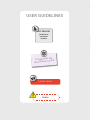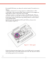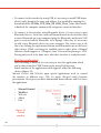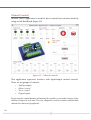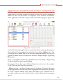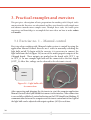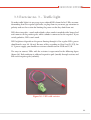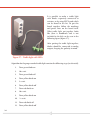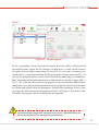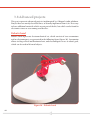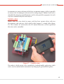
1
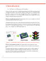
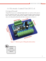
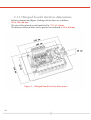
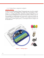
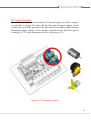
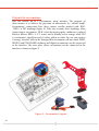
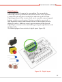
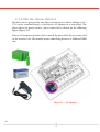
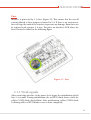
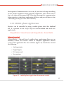
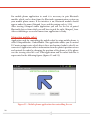
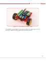
OKTOPOD
STUDIO
Construction kit for mechatronics,
robotics and automation
USER MANUAL
Teaching tool for technical and computer
science for grade 5 to 8 of elementary school
OKTOPOD STUDIO
Construction kit for mechatronics,
robotics and automation
Teaching tool for technical and computer science for grade
5 to 8 of elementary school
AUTHORS
Milan Romic
Robert Kovac
CONTRIBUTORS
Dragutin Debeljkovic, PhD, professor at Faculty of
mechanical engineering, Belgrade
Branislav Tejic, ma ing. of mechatronics, teaching assistant at Faculty of
Technical Science in Novi Sad
Radoje Ceranic, professor of technical education at “Jovan Miodragovic”
elementary school at Belgrade
EDITOR IN CHIEF
Vojkan Lucanin, PhD
DESIGN AND GRAPHIC PREPARATION
DTP ENTER d.o.o.
PRESS CORRECTOR
Ivana Simic Golubovic
PUBLISHER AND CONTRIBUTORS
”OPSTA TEHNIKA” Agency for textbook publishing
Srecko Zivanovic, enterprenuer
Cede Pavlovica 8, Sibnica, Belgrade
Table of contents
1. Introduction
6
1.1 What is Oktopod studio?
6
2. Oktopod studio – Construction kit
8
2.1 Electronic Control Unit (ECU) –Oktopod board
09
2.1.1 Oktopod board interface dimensions 10
2.1.2 Connecting to computer 11
2.1.3 Interface input/output 12
2.1.4 Electric characteristics16
2.1.5 Work signals
17
2.2 Firmware - Oktopod Control 19
2.2.1 Computer application
19
2.2.2 Mobile phone application27
3. Practical examples and exercises
30
3.1 Exercise no.1 – Manual control
30
3.2 Exercise no.2 – Programming the blinking light bulb
31
3.3 Exercise no. 3 – Traffic light
33
3.4 Exercise no. 4 – Alarm!
36
3.5 Exercise no.5 – DC motor as fan
38
3.6 Exercise no. 6 – Making a mousetrap with servomotor
40
3.7 Exercise no. 7 – Regulating Temperature
42
3.8 Advanced projects 44
44
4. Summary47
USER GUIDELINES
KEY PHRASES
OVERVIEW OF
IMPORTANT
NOTIONS
S FOR
SUGGESTION
WORK
T
INDEPENDEN
USEFUL ADVICE
WARNING
ОКТОPOD STUDIO
Figure
Lesson title
Chapter
Key phrases
1 Introduction
1.1 What is Oktopod Studio
Oktopod studio represents a stimulating medium which allows making of and
starting mechatronics toys, models and low-voltage devices. Oktopod studio
kit allows control over the work of light bulbs, LEDs, electromagnets, DC
motors, servomotors, etc. It is also possible to make more complicated sets by
using the abovementioned materials.
What is a mechatronic device? Mechatronic devices are complex sets which
contain mechanical and electric parts.
Oktopod studio represents a reduced imitation of modern automated systems.
Just as any other automated system, it consists of software, electronic control
unit (ECU), and input/output features, as it is represented on the following
page – the example of a traffic light (figure 1).
Figure 1 – Automated system 8 (software, electronics, executive feature)
What is an automated system? An automated system represents a preprogrammed device which works with partial or no human intervention at
all.
To understand better how an automated systems work, we will compare it
to human organism. Human organism matches firmware: it instructs the
executive features (which are actually muscles), and collects information
from our senses (which match the sensors).
6
ОКТОPOD STUDIO
In this case, the nerve system would represent electronic control unit, in
other words “interface”, which carries information.
What is “interface”? “Interface” is an old term meaning “a surface forming
a common boundary, as between bodies or regions”. Today, interface
represents an electrical circuit used to connect parts which use “different
languages”.
Oktopod studio includes software and ECU used for controlling mechatronic devices.
Further on in the text is given a detailed description of Oktopod studio’s stimulating
medium with practical examples.
mechatronic
devices
automated systems
interface
7
2. Oktopod studio – Construction
Kit
This part describes how Oktopod studio kit works, from connecting hardware
(physical part – electronics) to installing and starting software (computer
application).
Contents of the kit:
1. Oktopod board electronic circuit with Bluetooth module
2. USB Bluetooth communication module for the computer
3. CD for software installation
4. AC adapter
5. 12 V light bulb
6. Colored LEDs (red, yellow, green, blue and white)
7. Resistors for connecting LEDs
8. Electric printed circuit board (PCB) for putting together traffic lights
9. Buzzer
10. DC motor with a propeller
11. Servomotor
12. Photosensor
13. Temperature sensor
14. Reed contact
15. Connecting cables
16. Heat shrinkable sleeve for insulation (20 cm)
Recommended tools:
1. Screwdrivers: slotted and positive
2. Pliers
3. Scalpel
4. Soldering iron
5. Duct tape
6. Caulking gun
7. Multimeter
8
ОКТОPOD STUDIO
2.1 Electronic Control Unit (ECU) of
Octopod board
Oktopod board represents an electrical circuit (further on: interface) which is placed
on a non-transparent, plastic base. Onto this electronic board we connect electrical
devices which we want to control using by computer or mobile phone. Next figure
shows what Oktopod board looks like and what its components are (figure 2)
Figure 2 – Hardware part of Oktopod studio medium
hardware
software
electrical circuit
modules
9
2.1.1 Oktopod board’s interface dimensions
Interface dimensions (figure 3) along with the base are as follows:
110 x 150 x 40 mm
The size of the printed circuit board itself is: 75.5 x 114 mm.
The distance between holes on the printed circuit board is: 69 x 108 mm
Figure 3 – Oktopod board interface dimensions
10
ОКТОPOD STUDIO
2.1.2 Connecting to a computer
Connecting to a computer or a mobile phone is done by USB or Bluetooth
module. These modules are separately connected to the printed circuit board.
The following figure (figure 4) represents the exact place on the interface
where USB and Bluetooth modules are to be connected.
Figure 4 – Connecting to a computer
The following figures represent modules connected to the interface. The
left figure represents connected USB module (figure 5), and the right one
Bluetooth module (figure 6).
Figure 5 – USB module
Figure 6 – Bluetooth module
11
2.1.3 Interfaces inputs/outputs
Analog outputs:
Interface has 8 analog outputs (figure 7) for general usage. Any devices which
use direct current can be plugged there: light bulbs, electromagnets, LEDs,
buzzers, etc. Analog outputs allow continuous voltage change from 0 V to
interface’s power feeding which can be between 6 and 12 V of direct current.
Every output has a bipolar plug used to secure the conductor, and they are
marked with plus (+) and minus (-) symbols. These outputs always have the
positive pole (+) while negative pole (-) is interrupted when the output is on
or disconnected.
Figure 7 - Analog outputs
12
ОКТОPOD STUDIO
DC motor outputs:
Interface has 2 outputs used to connect DC motors (figure 8). At these outputs
it is possible to change the value and the direction of output voltage, which
is how you control the speed and the direction of the motor’s shaft rotation.
Maximum output voltage at these outputs depends on the interface’s power
feeding (6-12 V), while maximum current can go up to 3 A.
Figure 8 - DC motors outputs
13
Outputs for servomotors:
You can control up to 3 servomotors using interface. The purpose of
these motors is to achieve the precision of movements (i.e. robotic hand).
Servomotors’ connections have three contact needles marked with: BLK, RED+ и SIG markings (figure 9). Take into account these markings when
connecting to servomotor: BLK- is for the negative pole; conductor is colored
black or brown; RED+ is 5 V source and is usually red or orange; while SIG
is servomotor’s signal line and it’s either yellow or white. In case you connect
it wrong, interface will not be damaged but servomotor will not work. MINI,
MICRO and STANDARD ordinary and digital servomotors can be connected
to the interface. The exact place where servomotors can be connected to the
interface is shown at figure 9.
Figure 9 – Servomotor’s outputs
14
ОКТОPOD STUDIO
Digital inputs:
Digital inputs detect change in the surrounding. They are made for
connecting switches, push buttons and various sensors. Every input has
a connection with two places to which the conductor can be attached.
Digital inputs detect short circuits which can be caused by connecting push
buttons, switches or reed contacts. Resistors can also be connected, i. e.
light-dependent resistors and thermal resistors. If the resistance of these
inputs gets under < 400 ohm, sensor’s input activation will be detected.
Digital input activation can be simulated by pressing the right button on the
interface itself.
The following figure shows interface’s digital inputs (figure 10).
Figure 10 – Digital inputs
15
2.1.4 Electric characteristics
Interface can be powered by any direct current source whose voltage is 6-12
V. It can be standard battery, a car battery, AC adapter or a solar panel. The
place where the power source can be connected is shown on the following
figure (Figure 11).
Power used to power interface has to match the one which devices connected
to the interface use.This usually means something between a 1000 and 3000
mA.
Figure 11 – AC adapter
16
ОКТОPOD STUDIO
Fuse:
Interface is protected by 3 A fuse (figure 12). This means that the overall
current allowed at these outputs is limited to 3 A. If there is an overcurrent,
fuse will stop the work of the interface to prevent any damage. Burnt fuse can
be replaced with a proper 3 A fuse. The place on interface’s PCB where the
fuse is located is shown in the following figure.
Figure 12 – Fuse
2.1.5 Work signals
After connecting interface to the power feed, begins the initialization which
lasts 3-4 seconds. During initialization, the red RUN diode shines, while the
yellow CONN diode slowly blinks. After initialization, yellow CONN diode
is shining while red RUN diode ceases to shine completely.
17
By using MODE button, you choose the interface’s mode. The modes are as
follows:
• Working with interface by using computer or mobile phone is called
CONN mode. When you successfully connect interface to the computer or
mobile phone, yellow CONN diode starts to blink.
• When the interface is working by itself, it’s called RUN mode. When in
this mode, interface executes pre-recorded program from its own memory.
In this mode, yellow CONN diode stops shining while the red RUN diode
starts blinking rapidly.
MODE button and signal diodes RUN and CONN are shown in the
following figure (figure 13).
Figure 13 – Work signals
Besides the abovementioned signals, there are also LEDs next to every input/
output which allow us to visually monitor their work. The only ones without
any working signals are the servomotors.
18
ОКТОPOD STUDIO
2.2 Firmware – Oktopod Control
Firmware is used to control the electronic unit (interface). A computer application has
been developed for Oktopod studio medium, but also a mobile phone application called
Oktopod Control.
2.2.1 Computer application
Computer application offerss a possibility to work with Oktopod studio hardware in
two ways. One way is manual control by using virtual control panel while the other
way includes programming by making a statement list. These possibilities, just like
installing and starting the application, are described in the following chapters.
Installing
Application which allows working with interface can be downloaded from the
website www.oktopodstudio.com or from the CD included in the kit. This
application is made for Windows platform, and it’s adjusted for Win XP / Win 7
/ Win 8. For application to work properly it’s necessary for the operating system
to be refreshed with Framework 3.5 or 4. To install it, run the file: setup.exe and
follow the recommended steps (figure 14).
Figure 14
– Installing
application
19
• To connect to the interface by using USB, it’s necessary to install USB driver
which can be found at the same web address. It is installed by running the
downloaded file: CP210x_VCP_Win_XP_S2K3_Vista_7.exe. After install
is finished, the computer automatically recognizes connected interface.
• To connect to the interface using Bluetooth device, it is necessary to pair
Bluetooth devices. To do this, turn on Bluetooth mode on the interface and
activate Bluetooth on your computer (plug the Bluetooth mode into USB
port or activate built-in Bluetooth on a laptop). After this, it’s necessary
to add a new Bluetooth device on your computer. The easiest way to do
this is by clicking the right mouse button onto Bluetooth icon in the lower
right corner. While searching for available devices takes place, Oktopod
interface should appear as “Oktopod_3xxx”. Password for pairing is: 1234.
Pairing only needs to be done once; after that, interface is ready for work.
Starting application
After installing is finished, it is necessary to start the application which
can be done from the START menu or by using Desktop icon.
Initial window of the application which appears, offers the following
choices (figure 15):
Manual Control and WishList open special applications used to control
the interface in different ways. Web site opens Oktopod studio’s Internet
presentation. About gives you basic information about software and Exit closes
the application.
•
•
•
•
•
Manual Control
WishList
Web site
About
Exit
Figure 15
– Initial
window
20
ОКТОPOD STUDIO
MANUAL
CONTROL
MODE
PROGRAMMING
Connecting to interface
After choosing the mode of the interface, (Manual
Control or WishList), a small window appears which
offers two ways of connection to the interface (figure 16): automatic (Auto Connect)
or manual (Manual). In addition, there is a possibility to open the application without
the interface having to be there (Offline Mode) and to quit (Back).
Figure 16 – Connecting to interface
21
Auto Connect option automatically finds the communication port where interface is
located. If this option cannot find interface, or it’s too slow (depending on the computer),
there is also the possibility to set up communication port manually (Manual) (figure
17).
Figure 17 – Connecting manually
22
ОКТОPOD STUDIO
For this way of connection, it should first be checked to which communication port is
interface located. This can be seen using Device Manager which is opened by clicking the
right mouse button on the following: My Computer >> Properties >> Device manager.
Right there, under Ports (COM & LPT), the existing COM ports are located, and this is
where you should check the number of COM ports in the brackets (figure 18).
Figure 18 – Device manager
USB interface appears as Silicon Labs CP210x USB to UART Bridge, while Bluetooth
interface will be represented as Standard Serial over Bluetooth link. In case there are
more Bluetooth ports, it is necessary to try which one has the working connection.
After establishing a successful connection, chosen application will open and active
communication will be marked by a blinking yellow light bulb.
23
Manual Control
Manual Control application is used for direct control over interface mode by
using virtual dashboard (figure 19).
Figure 19 – Manual control
This application represents interface with input/output control consoles.
There are for groups of controls:
•
•
•
•
Analog outputs
Motor control
Servo control
Digital inputs
By pressing the control buttons and moving the equalizers, you make changes on the
interface’s outputs in real-time. This way, computer is used as a remote control which
controls the connected peripherals.
24
ОКТОPOD STUDIO
Application for programming the interface’s work (WishList)
WishList application is used to program mode of the interface. By using this
application it is possible to make statement lists (in other words: a program)
which are later executed from the computer or the memory of interface.
What application looks like is represented in the following figure (figure 20).
Figure 20 – Statement List
On the left side of the application are controls used for working with interface,
like in Manual Control application, only these have button Add next to it. The
set output state is added into the list of events using that button. This way it is
possible to make a desired sequence of interface’s output changes by pressing
Play button.
There is a possibility to make three parallel lists of events (Prog 1, Prog 2, Prog
3) which would be equal to multitasking.
To program the modes, some additional functions can be used, for example:
Delay, Wait until and Start/Stop programs:
- Delay function is used for determining the duration of the pause between
certain operations. This function allows to program the time for the execution
of events. Without adding Delay order, functions in the statement list are
executed straight away, one after the other, without delay and at maximum
speed.
25
- Wait until function is made for using interface’s input as a condition for
executing the program. This function stops the execution on the event list until
the desired change on the input happens. It can be activation or deactivation of
connected sensor or integrated key on the board. When the expected condition
is fulfilled, program continues executing orders. By using this function it is
possible to connect the work of the interface with external events.
- Start/stop programs function allows certain parallel programs to start and
stop. With this function it is possible to start or stop certain program from a
different program. With this function you get the possibility to create more
complex algorithms for managing and controlling the interface.
У гoрњeм лeвoм дeлу aпликaциje, пoстoje дугмaд зa кoнтрoлу извршaвaња
листe жеља. Дугмaд Play и Stop започињу и зaустaвљају извршaвaњe
прoгрaмa дoк је пoмoћу дугмeтa Step мoгућe извршaвaти прoгрaм кoрaк
- пo - кoрaк, штo пoмaжe схвaтaњу нaчинa рaдa и нaлaжeњу eвeнтуaлних
грeшaкa.
In the upper left corner of the application, there are buttons for control of
execution of statement list. Play and Stop buttons begin and end execution of
programs while by using button Step it is possib le to execute program step-bystep, which helps us understand the ways it works and find possible mistakes.
With Download2Interface button, program is recorded in the memory
of interface from where is later possible to execute it without having to use
computer. After saving the program in interface’s memory, and by pressing
the MODE button in interface’s hardware, interface enters RUN mode – which
is represented with a blinking red diode – and execution of recorded program
begins. This allows autonomous operating of the interface.
To change the program, use Clear line and Clear prog buttons. These allow
you to erase one line of the program or the entire program. Changing the
parameters of certain lines is possible by ‘double clicking’ the selected line using
your mouse. After this, a window opens offering you possible changes. Next to
this, there is also the possibility to rearrange the lines by drag-and-dropping
them with your mouse.
Located in the upper right corner of the application are the buttons for loading
previously saved programs Save project and Load project. There is also the
Connect/Disconnect button which makes it possible for us to establish and/
or interrupt communication with the interface, while active communication is
marked by the blinking of status-light bulb.
26
ОКТОPOD STUDIO
Interruption of communication is necessary if you want to change something
on the interface hardware during program compilation, which means that it
has to be taken off the power feed. If you don’t interrupt the communication
before interface is shut down, application will freeze and you will have to shut
it down (by pressing Ctrl+Alt+Delete buttons).
2.2.2 Mobile phone application
Interface can be controlled by using a mobile phone which has Android
OS. It is possible to visit Google Play Store and download and install two
applications:
OktopodStudio - ManualControl and OktopodStudio - Robot Mobile.
Manual control
OktopodStudio – ManualControl, mobile phone application allows you to
manually control the interface similar to computer application Manual
Control. This application has four windows (figure 21) intended to control
the following:
•
•
•
•
Analog outputs,
Digital inputs,
DC motors and
Servomotors.
Figure 21 – mobile phone application for manual control
27
For mobile phone application to work it is necessary to pair Bluetooth
module which can be done from the Bluetooth communication section on
your mobile phone menu. If the interface is on, Bluetooth module should
appear under the name Oktopod_3xxx, and the pairing code is: 1234.
After starting Oktopod studio application you will see the list of paired
Bluetooth devices from which you will have to pick the right Oktopod_3xxx.
After establishing a successful connection, application is ready.
Managing mobile robot
Application used for controlling the mobile robot by using mobile phone, is
called OktopodStudio - RobotMobile. This application allows you to control
DC motor outputs onto which direct drive mechanisms (robot’s wheels) are
connected. Application collects information from the phone’s position sensor
and controls the robot by changing the position of the phone as if the phone
was the steering wheel of a car. What application and the robot look like is
represented in the following figures (figures 22 and 23).
Figure 22 – Mobile phone application for controlling the car
28
ОКТОPOD STUDIO
Figure 23 – An example of a mobile robot
To establish a connection it is necessary to follow the same steps as in the
previously explained mobile application for manual control.
29
3. Practical examples and exercises
This part gives a description of basic preparations for working with Oktopod studio
construction kit. Exercises are educational and they start from the really simple ones
and advance towards more complex ones. Through these tasks, the reader gains
experience and knowledge to accomplish their own ideas on how to make robots
and models.
3.1 Exercise no. 1 – Manual control
First step when working with Oktopod studio system is control by using the
application Manual Control. Exercise no. 1 refers to manually switching the
light bulb on/off. To begin with the exercise, it is necessary to connect the
light bulb from the kit (figure 24) to one of the multi-purpose outputs of the
Oktopod board. These outputs are marked on the board with OUT_1 up
to OUT_8. In our example light bulb will be connected to the first output
(OUT_1). After this, voltage can be released to the electronic circuit.
robots
models
Figure 24 – Light bulb with
its connection
After connecting and plugging the electronics in, start the computer application
Manual Control, where you should first connect to the interface. After connection
is successfully established, control indication on the PCB should start blinking. If
communication between the computer and electronic control unit is fine, light of
the light bulb can be adjusted with output equalizer (AO1) in real time.
30
ОКТОPOD STUDIO
the Android
Test the work of
t some of
app by trying ou
your own ideas!
In case the connected light bulb is
meant to be used with lower voltage
(i.e. 6 V), and interface’s voltage is 12
V, light bulb will burn out quickly.
In another case, if the light bulb is
meant for higher voltage (i.e. 24 V),
its light will be dimmed.
3.2 Exercise no. 2 – Programming the
blinking light bulb
Second exercise refers to automatically switching the light bulb on/off by
making statements (WishList). First thing to do is connect the light bulb
to one of multipurpose outputs on the Oktopod board (i.e. OUT_1), as was
the case with the previous exercise. After connecting, bring power feed to
electronic circuit and run the WishList computer application.
After connection is established, you can test the light bulb by moving the equalizer
for the output 1 (Out 1). If everything is set, you can start programming. Algorithm
for blinking light bulb has four steps:
1. Turn the light bulb on
2. Wait
3. Turn the light bulb off
4. Чeкaњe
Turning the light bulb on can be done by setting the equalizer for Out 1 in the desired
position. After that, the set state should be recorded onto the statement list by pressing
the button ADD, which is located under the equalizer. After this step, the recorded
command appears in the left window. Then you assign the “wait”, time during which
the light bulb will stay on. This is done with Delay equalizer. The set time adds to the
statement list in the similar way, by using the button ADD. The following example
uses 2 s pause.
31
After the pause, it is necessary to turn the light bulb off so the equalizer for output 1 is
in ‘off ’ position (0%). This state is also added to the list by pressing the button ADD.
After this step, it’s necessary to add another pause, which is done in the similar way,
by using the Delay equalizer. Taking into account that after the last order, program
automatically starts again; this makes the blinking program complete (figure 25).
Figure 25 – Blinking light bulb program
By pressing PLAY button, you start the program. If program’s work is satisfying, it is
possible to record it to interface’s memory by using Download2Interface button. After
recording this, interface switches to the mode for the execution of programs from its
own memory until you press OK button on the warning window. Program which is
recorded this way can later be executed from the memory of interface, without the
computer, by pressing MODE button on the interface.
.
It is possible to modify the function
by double clicking on the certain
lines in the program.
32
ОКТОPOD STUDIO
3.3 Exercise no. 3 – Traffic light
To make traffic lights it is necessary to use colored LEDs from the kit. LEDs are more
demanding than the regular light bulbs, to plug them in you must pay attention to
polarity and use the resistor for limiting the power so that they don’t burn out.
LEDs have two poles – anode and cathode, where anode is marked with a longer lead
and connects to the positive pole, while cathode is connected to the negative. If you
switch polarities, LEDs won’t work.
LED brightness depends on the power flowing through it. For regular LEDs, power
should not be over 20 - 30 mA. Because of this, according to Ohm’s law (R=U/I), for
12 V power supply, you should use resistors valued between 470 R and 1,2 K.
The ways to connect LEDs with the resistors is represented in the following figure
(figure 26). Red conductor is soldered to positive pole (anode) through resistor, and
blue to the negative pole (cathode).
Figure 26 – LED with resistor
33
It is possible to make a traffic light
with diodes separately connected to
resistors, or by using EPC board which
can be found in the kit. To put this
board together, follow the markings
and power lines on the board itself.
What traffic light put together looks
like (box is handmade and is not
included in the kit) can be seen in the
following figure (figure 27).
After putting the traffic light together,
diodes should be connected to analog
outputs, keeping the polarity in mind.
Figure 27 – Traffic light with LEDs
Algorithm for the proper work of traffic light contains the following steps (accelerated):
1.
Turn green diode on
2.
10 s wait.
3.
Turn green diode off
4.
Turn yellow diode on
5.
3 s wait.
6.
Turn yellow diode off
7.
Turn red diode on
8.
10 s wait.
9.
Turn yellow diode on
10. 2 s wait.
11. Turn red diode off
12. Turn yellow diode off
34
ОКТОPOD STUDIO
Program is implemented in the similar way as in the previous exercise, by turning
on certain outputs and adding pauses between operations. Since the program is
automatically repeating, only one sequence for the traffic light diodes is necessary
(figure 28).
Figure 28 – Program for traffic light work
e program in
Try changing th
e green light
such way that th
es before
blinks three tim
going off !
35
3.4 Exercise no. 4 – Alarm!
To make an alarm system, it’s necessary to use burglary detection sensors. These
sensors give information to control electronics of human presence, and this activates
corresponding alarm signal: siren, light, etc. In this exercise, we will use interface’s
digital input to connect sensors and buzzer will go on as the alarm signal.
Phase 1:
In preparation for this task it is necessary to connect the buzzer to one of the
multipurpose outputs on the Oktopod board (i.e. OUT_1). In step one, one of the
inbuilt buttons on the interface itself will be used to detect events. If button pressure
is detected, buzzer should go off for 1 s. For this to happen, the following algorithm
should be implemented:
1. Wait for button activation
2. Buzzer going off
3. 1 s wait.
4. Turn off the buzzer
5. 1 s wait.
Change of state on the digital outputs is detected by Wait Until group of functions.
Wait Until Input 1 Activated function stops
the program until button 1 is pressed. The
following step in the program, assuming
that button was activated, should be buzzer/
output 1 activation (OUT_1 = 100%).
For this exercise you can use
After this, you wait for 1 s (Delay 1 s) and
program similar to the one used in
the buzzer turns off (OUT_1 = 0%). After
exercise 2 for the blinking of the light
turning off, another pause should be added
bulb. Add initial condition: waiting
(Delay 1 s), after which the program goes
for the input information.
back to start. Program will turn the output
on/off for as long as button 1 is pressed.
What this program, practically implemented, should look like is represented in the
following figure (Figure 29).
36
ОКТОPOD STUDIO
Phase 2:
Figure 29 – Alarm program
In the second phase, contact detector for burglar detection will be used instead of
the inbuilt button. Inputs on the interface actually detect a short circuit between
two poles between input connections. To test this, it is necessary to connect two
conductors (i.e. using material from the kit) to the poles of input connector IN_1. If
you run the program, buzzer can be activated by briefly connecting two conductors.
Brief connection of the pole’s connection is allowed only at interface’s inputs (IN_1,
IN_2,... IN_4) because if it is done at the outputs, it can cause burnout. Ends of these
conductors can be placed at the main door in such way that they touch when the door
are closed, and separate when the door opens. To detect this separation, it is necessary
to change the first function in the program to Wait Until Input 1 Deactivated. This
will make the program run when conductors are separated.
You can notice that the program looks similar to the one in exercise 2 (light bulb blinking), only
that the initial condition is added: waiting for the input information.
37
Phase 3:
In the final phase, contact conductors are replaced by reed contact from the kit
(figure 30).
Figure 30 – Reed contact
Reed contact creates contact if a magnet is located nearby. It is possible to install it
at the door frame, and to install a magnet at the door wing, so the detector is near
the reed contact for as long as the door is closed. When the door opens – contact
breaks. This solution is more elegant and reliable because there is no danger of losing
the contact and it’s easier to install. This is the way many professional alarm systems
work.
3.5 Exercise no. 5 – Using DC motor
as a fan
In this exercise, DC motor with a propeller will be used as a fan. It is necessary to
connect DC motor from the kit to one of the two outputs for DC motors (for example
DC motor 1), and set the propeller to motor shaft. The fan should have three speeds,
one of which can be selected by using entry buttons on the interface board. As long
as one of the buttons is pressed, fan should spin at one speed, and after it’s released,
fan should stop. Button 1 should turn the fan on the lowest speed (25%), button 2
at medium speed (50%), and button 3 at maximum speed (100%). Whether buttons
38
ОКТОPOD STUDIO
1, 2 or 3 are pressed, is detected by three parallel programs which operate at the
same time. Each program checks if one of the buttons is pressed. These programs are
written is separate windows Prog 1, Prog 2 and Prog 3, and each has the following:
1. Wait for a button to be activated,
2. Start the motor at the proper speed,
3. Wait for the right button to be deactivated
4. Turn the motor off
To illustrate this, the following figure shows another subprogram for starting the
engine at medium speed using button 2 (figure 31).
Figure 31 – Subprogram for starting the motor at medium speed 50%
By clicking PLAY, each subprogram starts
simultaneously, and each is waiting for the right
button to be activated; depending on which button
is activated, motor will start at the right speed.
ons at the
Press more butt
see what
same time and
happens.
39
3.6 Exercise no. 6 – Making a mousetrap with
servomotor
In this exercise servomotor from the kit will be used to make a mousetrap (figure 32).
Figure 32 - Servomotor
It is necessary to place a stick under the box so the mouse can go in. The stick should
be connected to the servomotor with a rope, so that by changing the position, stick
can be pulled out from under the box and the mouse can be caught. Reed contact
placed under the box can be used to detect a mouse (similar to the exercise 4 for
the alarm). Magnet for the activation is placed in a piece of cheese close to the reed
contact. In case a mouse gets under the box and moves the cheese, contact with the
reed contact will be lost, and servomotor will activate, which will pull the stick from
under the box. Mouse is caught!
40
ОКТОPOD STUDIO
Mousetrap program is represented in the following figure (figure 32).
Figure 32 – Mousetrap activation program
dependent
Suggestion for in
light detector
work – Make a
stead of
for the mouse: In
nnect photoreed contact, co
put and
resistor to the in
a nonpoint an LED or
lb (connect
blinking light bu
) into it. If a
it to any output
ts the light
mouse interrup
istor will lose
beam, photores
and it will
its conductance
h.
activate the switc
41
3.7 Exercise no. 7 – Regulating temperature
The simplest way to regulate temperature is so called On-Off regulation. This means
that, if the temperature is lower than desired – heater goes on, and when the desired
temperature is achieved – heater turns off. (This is the way home electric heaters
work).
Since the kit does not contain heaters, a light bulb will be used, which produces a
significant amount of heat when turned on.
Thermo-resistor from the kit will be used to detect temperature. It is shown in the
following figure along with photo-resistor (figure 34). Thermo-resistor becomes
transparent when temperature is high and thus is able to activate input.
Figure 34 – Thermo and photo resistor
42
ОКТОPOD STUDIO
Light bulb should be placed near thermo-resistor so the change can be detected.
Program for the heater should look similar to what is represented in the following
figure (figure 35). The choice of inputs and outputs to which light bulb and thermoresistor are connected is arbitrary.
Figure 35 – Temperature regulation program
How does the program work? For as long as temperature is low, light bulb will stay
on and warm up the surrounding. When temperature is sufficient for the thermoresistor to activate the input – light bulb will turn off until the sensor is cool again
and so on.
dependent
Suggestion for in
ecting
work – Try conn
stead of a
photo-resistor in
and bring
thermo-resistor
ar. What is
the light bulb ne
happening?
43
3.8 Advanced projects
This part represents advanced projects implemented by Oktopod studio platform.
Project ideas are merely described since, to actually implement them it, its’ necessary
to have additional materials which are not part of the kit, but which can be found in
electronics stores or even among used devices.
Robotic hand
Robotic hand represents electromechanical set, which consists of two servomotors
and an electromagnet, as represented in the following figure (figure 36). Servomotor
allows circling vertical and horizontal axis, and electromagnet serves as robot’s grab,
which can be used to lift metal objects.
Figure 36 – Robotic hand
44
ОКТОPOD STUDIO
Servomotors are connected to any of the three servomotor outputs, while it is possible
to connect the electromagnet onto one of the analog outputs. Robotic hand can be
controlled by computer or mobile phone, and it is also possible to program it in such
way that it automatically lifts metal objects.
Mobile robot
Mobile robot uses two wheels to move, and they have separate drives with two
electromotors and redactors, while vehicle’s third support is a simple slider (figure
37). These motors are connected to the DC motor connectors, so their speed and
direction can be controlled.
Figure 37 – A mobile robot
This robot is chiefly meant to be controlled by Android mobile application, which
can be used to control robot’s movements by changing the position of the phone.
45
Model of a city with a railroad
Model of a city with a railroad is one of the most beautiful projects implemented
by using Oktopod studio platform. The model shown in the following figure (figure
38) contains system of railroads with a train and wagons, street lights divided into
multiple regions and a ramp at railway crossing.
Figure 38 – Model of a city with a railroad
All this has to be controlled manually, by using a computer or a mobile phone. It is
also possible to program automatic mode so that the city can move without human
presence.
46
ОКТОPOD STUDIO
4. Summary
We presented, in the previously described exercises, certain basic possibilities
and working techniques of a teaching tool for working on a computer – OKTOPOD
STUDIO construction kit.
By mastering these, you gain knowledge which allows you to implement your
own, even more complex ideas by combining several techniques.
This teaching tool does not have to be used only in classrooms and science labs,
but it can be applied in real-life projects as well.
When working with OKTOPOD STUDIO kit, pay attention to its limitations,
since otherwise it can lead to various irregularities in work. These limitations are, as
follows:
- It’s not meant to be used with high-voltage devices. It is possible to do so, but
certain relays have to be used, and it’s not recommended for the inexperienced users.
- Oktopod_Control graphic software has limited programming abilities. More
advanced algorithms can be programmed by using software designed for that
purpose such as AVR Studio or MikroC.
- It’s not meant for professional and long-term usage in industrial conditions, but
only for teaching model control.
basic possibilities
working
techniques
limitations
47