1
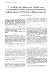
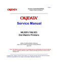
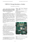
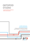
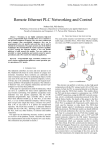
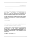
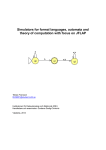
SYSTEM FOR AUTOMATIC MEASUREMENT OF SIGNAL LEVEL
IN GSM 900/1800 CHANNEL WITH GPS LOCALIZATION
Dusan Radovic1, Mirjana Simic2
1Institute ”Michael Pupin“, Belgrade, [email protected]
2Faculty of Electrical Engineering, Belgrade, [email protected]
I INTRODUCTION
For reliable mobile communications received signal level
must be above the receiver sensitivity. Determining of zone in
which this requirement is satisfied is done in the phase of
planning of mobile system by the various methods of electrical
field prediction. Calculated values, and the methods itself, are
verified by checking in the field. Measurement systems made
only for this purpose are fast, autonomous, and very expensive.
In Global System for Mobile communications (GSM)
mobile phones measure signal level received from base station.
The main idea of this work is to read-out signal level from the
phone and concurrently collects geographical coordinates of
measuring location. Combining data of signal level with
location coordinates transmitter coverage area can be presented
on a digital map [1].
There is previous work [2], [3] related to this coverage
determination problem. We expanded the choice of solutions
by our system that measures signal in any of GSM channels.
The system can be used for checking GSM test transmitter
coverage area or coverage of real base station transmitter. The
same configuration can be used for measurement of noise and
interference levels in any of the GSM channels that are not
used.
In the following section measurement system is presented.
Part III explains results of measurement. Section IV is
dedicated for performance analysis and comparison with
existing solutions. At the end conclusion and abstract are
given.
II MEASUREMENT SYSTEM
This section explains architecture of measurement system
and gives block diagram and front panel of measurement
software. Basic system configuration comprises laptop
computer, mobile phone and GPS (Global Positioning System)
receiver as shown in figure 1. It is possible to add external
antenna for phone and for GPS. Additional power supply may
be provided for all parts for longer measurements. Supported
phone models are from Nokia 61xx and 51xx series. GPS
receiver is Garmin II PLUS [4] or any other that supports
NMEA 0183 protocol [5].
First version of system was using MBUS protocol [6] for
communication with phone, which is on 9600 bit/s. In that
version we had ten readings in one second. Current version
uses protocol FBUS [6], because it enables faster data transfer
than older MBUS. By this protocol (and speed) change, we
obtained more than twofold decrease of one measurement
period. One could expect much more but the limiting factor is
in our phone that can send new signal level every 35ms.
Laptop computer
Mobile phone
FBUS 115200 8N1
NMEA
4800 8N1
GPS receiver
Figure 1. Main components of measurement system.
Communication between computer and phone and GPS is
achieved through serial (RS232) connection. With Nokia 6110
mobile phone it is used FBUS protocol, speed of 115200 bit/s
and 8data bits, no parity bit and one stop bit. GPS receiver
Garmin II PLUS uses NMEA 0183 protocol, speed of 4800
bit/s, no parity bit and one stop bit.
Measurement software, a Windows application written in
LabVIEW package [7], controls all system parts and
configures the entire system.
Communication with phone is based on sequences of:
- request from measurement software,
- acknowledge of request reception by phone,
- answer from phone and
- acknowledge of the answer reception by software.
Diagram of measurement process is shown in figure 2.
Phone is first initialized in a so-called local mode that enables
setting RF channel and reading signal level values. Reading of
is done in a while loop. After sending request, measurement
software waits until answer from phone comes, then process it,
displays value and writes to file.
On front panel, given in figure 3, default values of various
control parameters are given. Operator can change them all
before the measurement is started. Number of samples until
measurement is ended and some others is possible to change
during the measurement. Port numbers for peripherals can’t be
the same. GSM channel number in which measurement is to be
performed is chosen. In addition, identification on location of
measurement and operator are written. Minimal level of signal
is set too. It can be chosen to do time-triggered measurement
with and without GPS localization.
START
Check the apparatus
Yes
Problem?
No
Read-out and check
data from phone and
GPS
No
Problem?
packet is 700 bytes long and can be transferred in about one
second, which is performed in consecutive readings, in time
slots when waiting answer from phone. For each frame is
checked validity of location data because three or more
satellites are needed for reliable position fix.
From directly measured signal power level electrical field
level can be found by formula (1). Additive factor is dependent
on frequency, antenna gain and cable loss and for GSM
measurements it is about 140 dB.
Yes
E [dBµV / m] = P [dBmW ] + Add . factor [dB] (1)
Operator should put appropriate value for additive factor in
front panel and measured values would be converted to
electrical field level, shown on graph, and put in file.
III RESULTS
Write data to output
files
No
Communication
with operator
End?
Yes
END
Figure 2. Simplified block diagram of the
measurement process controled by software.
Communication with GPS is simpler. Computer listens on
GPS port and reads data. According to NMEA format data are
divided, by GPS, in frames which are generated every two
seconds. Each frame consists of 12 subframes in which are
contained many information for user.
All measured values are saved in two output files in ASCII
form suitable for further manipulation. In file *.mob signal
level in GSM channel is written, and in *.gps geographical
coordinates of measurement points, where “*” denotes the
same file name chosen by user. The correlation of two files is
explained in figures 4 and 5. In both files header and footer
gives basic information of concrete measurement. If the
position data are not available in *.gps file is written text “No
satellites!”.
File name:
Date [mm/dd/yy]:
Location:
Operator:
Measurement started at:
GSM channel number:
Minimal level [dBm]:
Additive factor [dB]:
measure83.mob
10/23/02
test location
test operator
06:29:46 PM
83
-102.0
0.00
Sample Value
1
-54.5
2
-54.4
3
-54.1
4
-54.3
5
-54.6
……………....
29996 -53.3
29997 -53.6
29998 -53.1
29999 -53.3
30000 -53.2
Figure 3. Front panel of measurement software during the
testing with real GSM signal and simulated GPS position. It is
easy to use and very flexible for various computer
configurations.
We have used first subframe GPRMC (GPS and Transit
Specific) from which localization data are extracted. Whole
Date [mm/dd/yy]:
Measurement ended at:
Average meas. period [ms]:
10/23/02
06:55:01 PM
49.89
Figure 4. Start and end of output file measure83.mob with
signal level values in 83rd GSM channel. Note that average
measurement period is near 50ms.
A case where valid data from GPS receiver is not available is
rarely found. Possible loss of location data is in urban areas
with many tall buildings.
File name:
GPS position correction:
measure83.gps
latitude
0"
longitude +20"
10/23/02
06:29:46 PM
longitude
Date [mm/dd/yy]:
Measurement started at:
latitude
GPS
mob
1
40
45ø00'00.0"N
019ø41'35.0"E
2
80
45ø00'00.0"N
019ø41'35.0"E
3
120
45ø00'00.0"N
019ø41'35.0"E
4
160
45ø00'00.0"N
019ø41'35.0"E
5
199
45ø00'00.0"N
019ø41'35.0"E
................................................................................
767
29802 45ø00'00.0"N
019ø41'35.0"E
768
29842 45ø00'00.0"N
019ø41'35.0"E
769
29881 45ø00'00.0"N
019ø41'35.0"E
770
29921 45ø00'00.0"N
019ø41'35.0"E
771
29961 45ø00'00.0"N
019ø41'35.0"E
Date [mm/dd/yy]:
10/23/02
Measurement ended at:
06:55:01 PM
Figure 5. Output file measure83.gps with latitude and
longitude values paired with signal level measurements from
file measure83.mob (number in second column). Localization
data are same because GPS is in simulation mode.
IV PERFORMANCE ANALYSIS
Minimal period of measurement of GSM signal level can be
adjusted to less than 50ms and depends on computer
configuration. Coordinates from GPS receiver are obtained on
every 2 second. If the vehicle has speed of 20m/s (72km/h), the
minimal distance between successive measurements of GSM
signal is less than 1m and between two successively read
positions is about 40m.
For older computers average measurement time is increasing
if graph is displayed on the screen and if sound signalizes
lower level than settled limit. For this reasons it is possible to
switch off both during measurement.
Mobile phone does not have measurement speed of TS55-C3
(Table 1.), but has smaller dimensions and mass. Measurement
accuracy of system, inherited from phone, is better than 1dB,
which is like in TS55-C3. Calibration can be achieved by
procedure given in service manual for cellular phone [8].
Table 1. Comparison of solutions for GSM signal
measurement by minimal measurement time and frequency
band.
Our
Anritsu
Rohde &
system
ML521 A/B
Schwarz TS55C3
Minimal
< 50ms
50ms
3ms
meas. time
Band
GSM
25MHz to
GSM 900/1800
900/1800
1000MHz
V CONCLUSIONS
Measurement system presented in this paper is realized on
idea of effective signal level measurement in chosen GSM
channel and testing transmitter coverage by using available
and simple measurement equipment. Using mobile phone as
receiving unit it can be avoided use of complex measurement
receiver and signal level is detected by the very same receiver
the user has. Collecting geographic coordinates from GPS
enables coverage zone identification on digital map. During
the testing in laboratory system has shown expected reliability.
Presented system is more flexible and cheaper in comparison
with special ones but with higher measurement period.
As system speed is limited by phone further work should be
on speeding up measurement by using other series of Nokia
mobile phones. In addition, support for simultaneous
measurement on two or three mobiles (channels) may be
added, which is limited by number of serial ports on computer.
REFERENCES
[1] Gordana Zivanovic, Aleksandar Neskovic, Natasha
Neskovic, George Paunovic, Processing and Graphical
Presentation of GSM Signal Level Measurements, TELFOR
2000, Belgrade
[2] Mirjana Simic, Rastko Zivanovic, Aleksandar Neskovic,
George Paunovic, System for Automatic Electric Field Level
Measurements with GPS Localization, TELFOR 2000,
Belgrade
[3] Rastko Zivanovic, Mirjana Simic, Aleksandar Neskovic,
George Paunovic, Automated System for GSM Signal Level
Measurement Using GPS Localization, TELFOR 2000,
Belgrade
[4] GPS II PLUS, Owner's Manual & Reference, GARMIN
Corporation, 1997
[5] NMEA 0183 Interface Standard, Version 2.30, National
Marine Electronics Association, 1998
[6] FBUS and MBUS protocol, http://www.gnokii.org
[7] LabVIEW User Manual, National Instruments, 1998
[8] Service manual for NOKIA cellular phones
Acknowledgement: Measurement system is realized at
Laboratory for radio-systems, Telecommunication department,
Faculty of Electrical Engineering in Belgrade.
Abstract: Main goal of this paper is presentation of a mobile,
flexible and economical solution of automated system for
measurement of signal level in chosen GSM 900/1800 channel.
Measurement system comprises cellular phone and satellite
radio-navigation system receiver connected to laptop
computer. Full automatization of the measurement process is
achieved by software, implemented in LabVIEW software
package that controls and manages the system. Accuracy of
measured signal level is better than 1dB and measurement
period is less than 50ms. System is suitable for fieldwork and
can be used in testing coverage of transmitter or when
checking interference levels. Comparison of our solution with
existing solutions is also given.