1
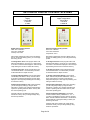
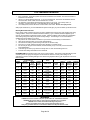
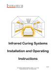
HI-INTENSITY MEDIUM WAVE IR CURING SYSTEMS USER’S MANUAL MEDIUM WAVE SYSTEMS MODELS S 2002 With Programmable Digital Controls SR 2002-IR With Programmable Digital Temperature Controls Congratulations on your purchase of an INFRATECH Hi-Intensity Medium Wave Curing System. These systems have been designed, tested and engineered to give optimum performance, ease of operation and many years of reliable, productive use. INFRATECH uses the latest technology and the best components available when designing and manufacturing our medium wave infrared paint curing systems. From our new hi-tech elements and our new “run cool” vented cassettes that protect the systems wiring and other components to our digital thermal control system that allows for curing by time and temperature providing the fastest, most accurate curing available. Manufactured and Distributed by: 15700 South Figueroa Street Gardena, California 90248 PH (800) 421-9455 FAX (310) 523-3674 www.infratech-usa.com One-Year Warranty Made In U.S.A. Page 1 of 4 UNPACKING & ASSEMBLY INSTRUCTIONS 1. 2. 3. 4. 5. 6. 7. Upon receipt, check packaging for visible damage. Immediately notify the freight carrier or distributor if any exists so a claim can be promptly filed. Carefully remove all packing, bubble pack, and cardboard boxes on the pallet. USE EXTREME CARE IN UNWRAPPING THE PRE-INSTALLED ELEMENTS. Tungsten Halogen elements are fragile! Carefully undo the staple that holds the foam around the elements. GENTLY and SLOWLY pull the foam out from around the element making sure that you do not torque the elements. Assemble mast and install on base. The control box / arm is pre-assembled and wired ready to insert into the vertical posts of the main stand assembly. The brackets are designed to accept the arm assembly and hold it in place while you use the same bolts that held the wooden shipping brackets in place to secure the arm in place. Unbolt the stand from the shipping pallet and remove the systems from the pallet. If you have any questions during assembly, please call (800) 421-9455 for assistance. Refer to operating instructions before using this curing system. ELEMENT REPLACEMENT INSTRUCTIONS 1. 2. 3. 4. 5. Check U.L. label on heater for model name, number and proper voltage. Remove end and center plate covers. Remove the grill guards by gently pulling down then out on the center post section. Then lift the bottom center position post of the guard until it comes out of its positioning hole. Slide the guard either left or right until the end comes out of its holes then slide out the other end. Remove the old element from its support, undo the wire nut connectors and safely dispose of the old element(s). (Caution: these elements are filled with inert gasses. When broken they shatter into small, sharp pieces of glass) To install the new element(s), carefully unwrap the element. Be careful not to touch the glass part. Place it in the built-in holder in the cassette and reverse steps 2 through 4. IMPORTANT NOTE: If you should touch then elements with you fingers, it will be necessary to clean them with denatured alcohol and cotton swabs. Oil from your fingers will cause a focused hot spot on the element and burn them out very rapidly. This type of premature failure is not covered under the systems warranty. BASIC OPERATING INSTRUCTIONS 1. 2. 3. 4. 5. 6. Plug unit into appropriate power source. To adjust systems operational height: Support the control panel handle and extension arms. Then loosen the slide lock knob on the mast slide assembly. With one foot on the stand base, lift or lower the entire assembly as required. Normal operating position for most jobs is half way up the mast. Be sure to adequately re-tighten the slide lock knob after you have repositioned the slider to prevent system control assembly from moving. Extension arm: To raise or lower the extension arm, simply depress the control handle located on the extension arms to the rubber stop and push up or down on the extension arms as required for positioning. Release the handle to lock in the desired position. Heater cassette assembly can be swiveled 270 around the extension arm. This makes a narrow foot print so the unit can work in tight locations. The heater head can also tilt down 90 by loosening the locking knob and moving the head down to the desired location. Each heater cassette can be individually adjusted to “clam shell” heat around corners or for doorjambs. When heaters are rotated outward, the unit heats a larger area and requires a little more time to cure. When heaters are swiveled in, the cure time and area is reduced. When heaters are swiveled in, consider using at a lower temperature to prevent vehicle damage. Position system so that the heater’s cassettes are from 18” to 36” away from the panel. IMPORTANT NOTE: NEVER POSITION HEATERS CLOSER THAN 18” FROM TARGET AREA. You should start out with systems heater cassettes positioned out at 36” away from the surface until you get a feeling for the power of the system and how to use the controls. Then you can move in closer as required. Page 2 of 4 SETTING UP DIGITAL CONTROL SYSTEMS Programmable Digital Control Box Functions S 2002 Programmable Digital Temperature Control Box Functions S 2002 IR Digital Control Factory Presets: Flash Time: 3 Minutes Cure Time: 30 Minutes Intensity: 75% Power Auto-Temp Control Factory Presets: Flash Time: 3 Minutes Cure Time: 30 Minutes Temperature: 130 F With system plugged into power source and “Ready” light on, but prior to starting system, you can change the factory presets. With system plugged into power and “Ready” light on but prior to starting system you can change the factory presets. To Change Flash Time: Press program button until flash time LED flashes. Use arrow up or down button to increase or decrease time displayed. When the light stops flashing the new time is locked into memory. To Change Flash Time: Press program button until flash time LED flashes. Use arrow up or down buttons to increase or decrease time displayed. When the light stops flashing the new time is locked into memory. To Change Cure Time: Press program button until cure time LED flashes. Use exact same procedure as described above to adjust cure time. To Change Cure Time: Press program button until cure time LED flashes. Use exact same procedure as described above to adjust cure time. To Change Intensity Setting: Press program button until intensity LED flashes. Use up or down buttons to increase or decrease percentage of power output displayed. When light stops flashing the new setting is locked into memory. To Change Temperature Setting: Press program button until cure temperature LED flashes. Use up or down arrow buttons to increase or decrease the temperature displayed. When light stops flashing, new setting is locked into memory. Changes During Operation: With system operating you can change any setting by using the above instructions. However, any changes made when the systems is operating will not be held in memory after the current operating cycle. Changes During Operation: With system operating you can change any setting by using the above instructions. However, any changes made when the system is operating will not be held in memory after the current operating cycle. Changes made prior to starting the system will be locked into memory until you change settings using the above procedures. Change Temperature Calibration: The infrared sensor controller is factory calibrated to +/- 3 F. If you wish to recalibrate the control, press the program button until the calibration LED flashes. Use the arrow up/down buttons to change the setting to match your measuring instrument. Changes made prior to starting the system will be locked into memory until you change settings using the above procedures. Page 3 of 4 SYSTEM MAINTENANCE 1. 2. 3. 4. Every 4-6 months, unplug the system and remove end reflectors from heaters. Re-check connection of lead wires to the elements. Oil from your hands damages elements. If you touch the elements, clean them with denatured alcohol and clean cotton swabs. Make sure the elements are cool first. The reflectors on the heaters should be kept free of dust or over-spray. Use a damp cloth or, if necessary, some fine steel wool or a Scotchbrite® pad to clean residue off. On a weekly basis, blow off IR sensor and dust with a cotton swab. Do not over-spray sensor. With proper maintenance, your new INFRATECH system should give you years of reliable, productive service. Working With Infrared & Paint Every coating system, applicator and shop has many variables that come into play when applying and curing coating systems. Some of the variables include the following – type of material, thickness applied, type of reducer, air temperature and ambient moisture content. All these variables must be taken into consideration when setting curing time settings and power intensity settings. The following is our recommendation to establish the correct setting for your shop. 1. Mix paint for the current weather conditions in you area as recommended by the manufacturer. 2. Start with an intensity setting of 75% power (default setting). 3. Set cure time according to product being cured (refer to cure time chart). 4. If the job is not cured, add more time at the same intensity to complete the job. 5. For the next job using the same materials, increase intensity 5% (or 10% max.) and use the same recommended time. 6. At the first sign of solvent pop, back the intensity down 5% and use that setting down 5%. 7. Increase time settings until desired cure is achieved. EXTREME CARE must be taken when using non-IR control systems. Technicians not familiar with the power of these systems are highly encouraged to use the maximum distance or lower power settings on all applications to assist in avoiding damage to the vehicle being repaired until they gain experience in the use of these systems. Programmable Temperature Control Models Heated Approx. Digital Distance Area Cure Time Temp From Settings Panel Cure Times Chart PAINT TYPE Programmable Digital Control Models Heated Area Approx. Cure Time Power Intensity Settings Distance From Panel 4’ x 4’ 6 min. 80% 24” 5’ x 6’ 10 min. 100% 36” 4’ x 4’ 15 min. 80% 24” 4’ x 6’ 15 min. 100% 36” 4’ x 4’ 18 min. 80% 24” 4’ x 6’ 20 min. 100% 36” 4’ x 6’ 20 min. 100% 36” 4’ x 6’ 20 min. 100% 36” 4’ x 4’ 6 min. 180º 24” 4’ x 6’ 10 min. 140º 36” 4’ x 4’ 10 min. 180º 24” 4’ x 6’ 15 min. 140º 36” 4’ x 4’ 18 min. 180º 24” 4’ x 6’ 20 min. 140º 36” 4’ x 6’ 20 min. 140º 36” 4’ x 6’ 20 min. 140º 36” Water based primer Water based primer Solvent based primer Solvent based primer High Solids Clear High Solids Clear Urethane Clear Coat Polyurethane Clear Coat 4’ x 6’ 20 min. 140º 36” Acrylic Enamel 4’ x 6’ 20 min. 100% 36” 4’ x 6’ 20 min. 140º 36” Lacquer 4’ x 6’ 15 min. 100% 36” WARNING ●NEVER block front of heater ● DO NOT operate within 25’ of flammable materials● ●DANGER: Do not use within 10’ when spraying operations are in progress● ●NEVER service heater without disconnecting from power● ●Source of possible shock ● Use only with grounded power source● ●Only use grounded extension cords that are rated for the amp load of these units● Page 4 of 4