1
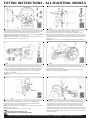
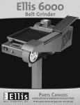
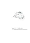
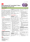
Multitool
WWW.MULTITOOLGRINDER.COM
SAFETY INSTRUCTIONS
WARNING:
To avoid mistakes that could cause injury, do not use the Multitool until you
have read and understood the following:
1.
2.
3.
4.
5.
6.
7.
8.
9.
10.
11.
12.
ALWAYS WEAR EYE PROTECTION. A full-face visor is preferred. Any Belt/Disc
Grinder can throw foreign objects into the eyes.
AVOID EYE CONTACT WITH BELT OR DISC. The abrasive belt when running is
an aggressive cutting tool. Extra care should be exercised when using coarse
grit belts because of their rapid cutting action.
KEEP CHILDREN AWAY. All visitors should be kept a safe distance from the
work area.
BOLT THE BENCH GRINDER securely to the bench or supporting surface to
stop it from tipping over or moving when in use.
DO NOT MOUNT the attachment protruding into walkways.
KEEP WORK AREA CLEAN. Cluttered areas and benches invite accidents.
ALWAYS WEAR A DUST MASK to prevent dust inhalation when adequate
ventilation or extraction is not available.
DO NOT WEAR LOOSE CLOTHING, which may become entangled in the
machine. Wear protective hair covering to contain long hair.
ALWAYS HOLD the work piece firmly when grinding and apply a light and
steady pressure against abrasive disc or belt.
ALWAYS GRIND ON THE DOWNWARD SIDE of the grinding disc. Grinding on
the upward side of the disc could cause the work piece to fly out of position,
resulting in injury.
DO NOT USE BELTS THAT ARE DAMAGED, TORN, OR SHOW SIGNS OF WEAR
ALWAYS INSTALL BELTS with arrows in the back of the belts pointing the
correct direction. Belts with lap joints must be fitted facing the correct
direction. See sketch below.
INTRODUCTION TO BELT GRINDING
Belt grinding or finishing has many advantages over the use of conventional grinding
wheels. It is possible to remove material up to 5 times faster than the equivalent grade
of grinding wheel with far less heat. The electrostatic process used in the manufacturing
of an abrasive belt ensures that the sharp side of each piece of grit is facing outwards on
the belt thus giving cleaner, smoother and faster cutting. The flexing of the belt has a
self-cleaning and cooling action, making it more suitable to any application where heat
could damage the work such as grinding leather, plastics, tool sharpening etc.
BELT APPLICATIONS
ALL METALS
COARSE FINISH
MEDIUM TO FINE
VERY FINE
MICROFINISHING
HEAVY GRINDING
ALUMINUM
Always use belt grease to prevent clogging.
WOOD
Use Aluminum Oxide Resin Bond (open or closed)
40, 60, 80, 100 or 120 Grits
Use 40 to 80 Grit
Use 120 to 180 Grit
Use 220 to 400 Grit
Use 3M Trizact 700 to 1200 Grit
Use Zirconia Belts 24, 40 or 80 Grit
PLASTICS & GLASS CERAMIC
Use Silicon Carbide Resin Bond 40 to 600 Grit
BELT AND DISC
GRINDING ATTACHMENT
OPERATING INSTRUCTIONS
BELT CHANGING
To remove the belt simply push down on the underside of belt to compress the tensioner assembly.
Catch automatically holds the slide in retracted position. When refitting the belt simply release the
catch (Fig 3:O) Always make sure belt lap faces the correct direction (see diagram left).
BELT TRACKING
Always ensure the belt entirely covers the rubber contact wheel. Adjustment is made when
running or when belt is rotated by hand. To adjust left, move tracking lever down. To adjust right,
move lever up. If tracking lever is constantly set in up or down position refer to Figs 5 & 6 of fitting
instructions on reverse side.
PLATEN GRINDING (HORIZONTAL OR VERTICAL)
It is important that the Platen (Fig 4: P) is not set too high. If belt is deflected and rides up over the
platen it creates an undue strain on the grinder, especially when starting. If platen is not often used
it is better to set a little clear of the belt. A simple method to adjust the platen is to place a straight
edge on top of the belt between the contact wheel and drive pulley and raise platen so that it just
touches under side of belt. Work of any length can be surfaced on the platen, for example the saw
edges of wood from short pieces up to lengths of several feet. Never grind or sand on platen unless
you are sure belt lap is facing in correct position (See diagram at left).
DISC GRINDING
Whenever possible remove the belt when using the grinding disc. The disc grinder is a very versatile
part of the attachment that can be used for dressing small castings and components, patterns,
models etc. often eliminating costly machining. Tool and cutter sharpening is a simple task and
there is less chance of burning edges. With the addition of the table, lengths and angles are easy to
adjust. Dressing end grain flat and square has always been a difficult task but now it is a simple and
quick operation, making perfect joints possible. A rubber cleaning stick should be used regularly
to prevent build up wood resin. When changing a disc pad remove any remaining adhesive with a
solvent, e.g. Lacquer thinner, acetone (nail polish remover). Do not use household cleaners.
CONTACT WHEEL GRINDING, POLISHING, AND SANDING
Using the front contact wheel removes material many times faster than a conventional grinding
wheel. The unique smooth cutting action is cooler, faster and safer than conventional grinding
methods. A good example of one of the many uses is the smoothing of welds and casting
blemishes prior to plating. Using the extremely fast and easy belt change it is possible to go from
a rough weld finish to a flat, smooth polish suitable to chrome plate in only two belt changes. e.g.
Remove rough weld with 40 or 80 grit belt. Remove grinding marks with 240 grit belt. Change
ground finish to smooth, brushed finish for plating using Scotchbrite super fine or Trizact belts.
Wood shaping and finishing can be done in a similar manner but belts should always be kept
exclusively for wood, especially in the finer grades. A rubber belt cleaning stick helps prevent
clogging on wood use.
FREE STRAPPING
Free strapping is a method of belt grinding, sanding or polishing where no backing is used behind
the belt. It is especially suitable for round and contoured work and some sharpening operations.
It is done on the underneath side of the belt opposite the platen. Belt grits of 180 to 400 are
recommended because of the rapid cutting action.
ATTACHMENT SPECIFICATIONS
MULTITOOL 362
Belt size 36” x 2” - Disc size 7” - Contact Wheel 3½” diameter. Fits most 6” or 8” bench grinders with
minimum ⅓ H.P. and shaft sizes of ½” or ⅝”.
MULTITOOL 482 & MULTITOOL 8CW
Belt size 48” x 2” - Disc size 7” - Contact Wheel 3½” diameter (8” diameter on 8CW). Fits most
bench grinders with minimum ½ H.P. and shaft sizes of ½” or ⅝”.
MULTITOOL 364
Belt size 36” x 4”- Disc size 7” - Contact Wheel 3½” diameter. Fits most 6” or 8” bench grinders with
minimum 3/4 H.P. and shaft sizes of ½” or ⅝”. (Note: Drive pulley can be bored to maximum 1”.)
MULTITOOL 484
Belt size 48” x 4” - Disc size 7” - Contact Wheel 3½” diameter. Fits most bench grinders with
minimum 1 H.P. and shaft sizes of ½” or ⅝”. (Note: Drive pulley can be bored to maximum 1”.)
BELT SPEED – ALL MODELS - Approximately 5000 Ft/min
AVAILABLE ACCESSORIES
ADJUSTABLE ANGLE WORK TABLE (MTBL) - for Disc Grinding
SHARPENING JIG (MTSJIG) – for sharpening chisels and planer blades
POLISHING ROUGE (MTRouge) - for use with Polishing Belts
WARRANTY AND CONDITIONS OF SALE
The words “us”, “we” or “our” refers to P.A Products or their authorized agent
A.) The warranty will only apply if the fitting and operating instructions are followed.
B.) The warranty will only apply for a period of 1 year from the date of original
purchase against any defect in our product, which can be proved, to our satisfaction to
have been caused by faulty materials or workmanship. Our liability is limited to the
cost of repairing or at our option, replacement of the defective goods or parts of the
goods. We will not be liable for any defect caused by unauthorized repair.
INSTRUCTIONS TO FOLLOW FOR WARRANTY CLAIMS:
1.
If warranty claim is made, we must be notified as soon as possible after assumed defect
has become apparent.
2.
Goods may only be returned with the approval and RGA # from Van Sant Distributing, Inc.
800-828-2043 or email us at [email protected].
3.
The customer must prepay all freight charges for returned goods.
4.
We will contact the customer with a suggestion after inspecting the goods to determine
with the customer what action should be taken in the circumstances.
FITTING INSTRUCTIONS - ALL MULTITOOL MODELS
1
E
2
B
4
3
Scan for Video
Disconnect grinder from power source. From the right hand end of the grinder, remove
wheel cover, wheel, wheel flanges and wheel guard. Fit slotted adaptor plate (A) using
either ¼” bolt (1), 5mm Bolt (2) or 3/16” Bolt (3) provided. Use appropriate size
washers under heads (B). The outer edge of the adaptor plate is tapered. Face smallest
side of taper away from grinder as shown in Fig 1: A.
NOTE: On 8” JET brand grinders use two additional washers between the grinder and
adaptor plate to clear flat head carriage bolts (Fig 2: E).
Scan for Video
Fit the Main Bracket (D) using flat head carriage bolts (E) through the three cut outs
(Fig 1: C) with flat head of bolt facing the drive pulley.* With angle face of
bracket approximately vertical, tighten ¼” nuts (4) evenly. If the Multitool is to be
used in a vertical position simply loosen nuts, tap main bracket (D) to loosen. Swivel to
desired position and retighten nuts (4). The above cutaway view is from the rear of the
right hand end of the grinder showing the tapered fit of the adaptor plate (A) and main
bracket (D).
*NOTE: If interference occurs, insert carriage bolt with head facing the grinder motor.
5
J
F
G
6
Scan for Video
Fit the idler arm (H) using 5/16” diameter bolts (J) and washers (5) provided. Fit one
of the heavy dished flanges (G) provided in the kit, that suits either ½” or ⅝” diameter
shaft size and check that it clears heads of bolts (Fig 1: B). If there is interference, use
either ½” or ⅝” diameter washer (pictured above and in Fig 2: F) behind the flange.
The drive pulley (Fig 4: K) comes with a 5⁄8” bore, there is a 1⁄2” steel bushing (6)
provided for smaller shafts.
NOTE: The 4” Drive Pulley in the Multitool models 364 & 484 can be bored to a
maximum of 1”.
Scan for Video
Fit the Drive Pulley (K) by sliding over the shaft of the grinder. Fit tightly against the
heavy dished flange (Fig 3: G) and use the 1⁄2” or 5⁄8” diameter washer (Fig 3: F) under the
nut and tighten with a socket or wrench.
NOTE: A poor quality nut may prevent pulley from running true. If this is the case,
replace factory nut with high quality alternative.
7
8
Scan for Video
Idler arm Cam plate (M) must now be set ¼” (6mm) clear of inside edge of the drive
pulley (Fig 4: K) Slots are provided under 5⁄16” bolts (Fig 3: J) for this adjustment.
Set tracking lever (N) in mid or horizontal position. Fit the belt and release spring
loaded contact wheel by lifting the catch (Fig 3: O)
NOTE: It is not necessary to remove the platen as in Figs 5 & 6. This has been removed
for clarity and instruction only.
NOTE: There will always be some parts left over after fitting.
For short instruction videos, see
www.youtube.com/vansantdistributing
Scan for Video
Pull the belt over a few revolutions by hand, if the belt wanders towards the drive
pulley (K), loosen the top bolt (J) and tap the top of the cam plate (M) in small amount
towards the drive pulley. If the belt moves towards the grinder, tap the top of cam
plate (M) towards the grinder. When the belt runs evenly on the contact wheel,
re-tighten bolt (J), turn grinder on to check. Final tracking adjustments can be done
with the tracking lever (Fig 5: N). Pulling the tracking lever down moves belt to the left,
up moves the belt to the right. Fit the cover plate using counter sunk screws provided
pictured above (7 & 8). Clean face of cover disc with a solvent and fit adhesive backed
abrasive disc provided.
For parts, tech support, belts, or discs contact Van Sant Distributing, Inc. at 800-828-2043 or [email protected]