1
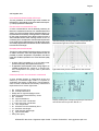
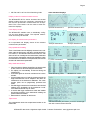
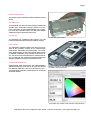
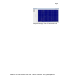
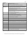
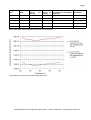
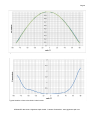
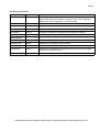
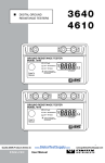
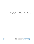
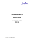
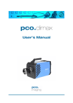
Page 1 BTS256-EF - mobile light meter for photopic and scotopic illuminance, EVE factor, luminous color, color rendering index, luminous spectrum and flicker. The BTS256-EF is a high-quality light meter that is well suited for illuminance and luminous color measurements in all application areas thanks to its compact design, high-quality light sensor and precise cosine field of view function. Another special feature of the device is its ability to perform flicker measurements. BiTec light sensor for complex light measurements One of the outstanding properties of this mobile light meter is its BiTec light sensor. This combines the characteristic properties of a silicon photodiode with those of a noise-free CMOS diode array. The BiTec sensor guarantees extremely precise photometric and spectral-radiometric measurement values over a large dynamic range through mutual correction of the measurement signals of both sensors. Silicon photodiode detector, fast and linear When taking into account the dynamic range, linearity and speed, silicon photodiodes have always been and are still the ultimate radiation detectors. A silicon photodiode is therefore integrated in the BiTec light sensor of the BTS256-EF light meter. Its matching to the photometric V(λ) responsivity is improved by correction with the spectral measurement data of the diode array. The photodiode is be used to determine the frequency of modulated light and thus evaluate the flicker risk. Compact, splashproof light meter with flicker measurement function for mobile use Flicker measurement Flicker measurement entails identification of a possible AC component of the light signal with a 5kHz bandwidth. Besides the flicker frequency, other flicker parameters i.e. Flicker percent and flicker index are also displayed. The device additionally performs a Fast Fourier Transformation so as to display other frequency components in the signal. For more details, see the technical article on flicker measurements under: www.gigahertz-optik.de/226-1+Flicker+measurment+with+BTS256-EF.html Standard display showing the signal progression and signal frequency Diode array detector for spectral measurement data The CMOS diode array of the BiTec Light sensor provides precise measurement data required for the luminous spectrum. This data is then used for calculation of the color values and scotopic illuminance as well as for optimization of the photometric responsivity. Optimized Signal to Noise Ratio The noise signal from diode array detectors has significant effect on the signal to noise ratio (SNR) and hence on the quality of the measurement signal as well. A remote controlled aperture in the BiTec light sensor enables online compensation of the dark signals that are dependent on the temperature Standard display showing the illuminance and flicker parameters BTS256-EF data sheet / Gigahertz-Optik GmbH - D 82299 Tuerkenfeld - www.gigahertz-optik.com Page 2 and integration time. Pulse Width Modulated (PWM) LED lamps The fast photodiode of the BiTec light sensor enables the BTS256-EF to automatically synchronize itself to the frequency of lamps operated in PWM mode. Precise cosine corrected field of view A cosine corrected field of view is absolutely necessary for illuminance measurement devices. For extended illuminance setups, the cosine goodness-of-fit has significant influence on the measurement uncertainty of the light meter. The BTS256EF light meter is equipped with a diffuser window that has a 20mm diameter whose cosine matching ensures an f2 ≤ 3% uncertainty which corresponds to the DIN 5036 requirements for the quality class B. Both detectors of the BiTec light sensor are centrally aligned behind the diffuser window and therefore have the same view angle. Standard display showing frequency components determined through Fast Fourier Transformation DIN quality class A and B luxmeter Through the cutting-edge Bi-Technology sensor concept, use of modern electronics, online dark signal adjustment and the possibility to perform temperature compensation, the device meets the conditions specified for two of the DIN 5036 quality classes. In terms of the f2 uncertainty i.e. ≤ 3%, the device corresponds to the quality class B (DIN 5032 section 7). In applications where limitation of the viewing angle is acceptable, the BTS256-EF , with its f1’, u, f3 and f4 values, corresponds to the quality class A (DIN 5032 section 7). Light meter with precise cosine field of view function Diverse photometric and colorimetric measurands A much broader diversity of measurands as the one offered by conventional light meters is required for verification and testing of LED lamps. The BTS256-EF offers fourteen measurands and thereby meets all the requirements for a modern light meter: Ep photopic illuminance Es scotopic illuminance Es/Ep ratio of night and daylight vision EVE “Equivalent Visual Efficiency” factor Ee irradiance Eλ spectral irradiance x, y CIE 1931 color coordinates u‘, v‘ CIE 1976 color coordinates CT color temperature ∆uv deviation from the blackbody locus λdom dominant wavelength λp peak intensity wavelength λ0,5 spectral half-width Purity color purity Display showing the scotopic and photopic illuminance and the S/P ratio as per IES TM-24-13 BTS256-EF data sheet / Gigahertz-Optik GmbH - D 82299 Tuerkenfeld - www.gigahertz-optik.com Page 3 CRI Ra and R1 to R15 Color Rendering Index Other standard displays Display modes for standard measurements The BTS256-EF Bi-Tec sensor luxmeter has several display modes where the necessary measurands for the common photometric measurements are incorporated. The cursor buttons can be used to switch between the displays. Spectral illuminance lx Spectral irradiance W/m² Photopic illuminance Scotopic illuminance x,y color coordinates u‘,v‘ color coordinates Color Rendering Index Normal color values User display modes The BTS256-EF enables users to individually configure and save display modes. The required measurands can hereby be selected. Info display for measurement parameters An incorporated Info Display shows all the relevant measurement parameters. Easy operation and handling Three control buttons and the diligently structured menu navigation make the device easy and safe to operate the device. For instance, in the standard measurement mode, the user does not have to manually set the measurement parameters since these are automatically and perfectly adjusted to match the measurement conditions. In the expert mode, the user has access to all measurement parameters. Many useful extra functions If the user wants to distance himself from the device’s field of view, he/she can set a time-delayed measurement. The display can automatically be dimmed during the measurement. An acoustic signal can be set to mark the end of a measurement. A layout created using a PC with the support points for the single measurements can be adopted in the device for measurement of the illuminance distribution. The measurement points can be progressively processed and saved. Fast data logger measurement mode where time-clocked readings of the photodiode can be recorded at a maximum measurement rate of up to 100ms. A second data logger measurement mode that enables time-clocked recording of all measurands including the spectral measurement data. Date and time in real-time can also be set. Tripod mount The measurement device has a tripod stand socket on the bottom side. The measurement parameters protocol is saved together with a measurement data file BTS256-EF data sheet / Gigahertz-Optik GmbH - D 82299 Tuerkenfeld - www.gigahertz-optik.com Page 4 Protective cap with chain The protective cap for the diffuser window is attached onto the device. Use without PC The BTS256-EF has all the necessary functions enabling free operation of the device without having to depend on a computer. Furthermore, the rechargeable batteries have a capacity of more than 8 operation hours. The USB power adapter enables recharging of the device without a PC. Use with PC The BTS256-E has a USB2 and WiFi interface. The USB interface enables both data exchange and battery charging. Socket with tripod thread User software The S-BTS256-E software included in the device’s price provides all the necessary functions for the measurements, measurement data display and data transfer. The cuttingedge, flexible desktop concept of the software offers the user an individual constellation of the required measurement values. This can be a full screen filled with lux measurement values or a matrix with both numerical and graphical fields. Each desktop constellation can easily be saved for future use. Software Development Kit Gigahertz-Optik offers programmers the S-SDK-BTS256-E Software Development Tool. This can be used with LabView from National Instruments, .NET from Microsoft and C/C++. The SDKs simplify integration of the BTS256-E in an internally developed software. Hard-top casing for safe transport and storage of the BTS256-E and accessories S-BTS256 user software with modular setup desktop BTS256-EF data sheet / Gigahertz-Optik GmbH - D 82299 Tuerkenfeld - www.gigahertz-optik.com Page 5 The graphical display module can be zoomed to full screen BTS256-EF data sheet / Gigahertz-Optik GmbH - D 82299 Tuerkenfeld - www.gigahertz-optik.com Page 6 Specifications Light meter DIN class B (DIN 5032 part 7) DIN class A for f1’, u, f3 and f4 (DIN 5032 part 7) Light sensor Bi-Technology Sensor with a photodiode broadband sensor and a 256 pixel CMOS diode-array. Integrated aperture for automatic dark signal adjustment. Input optic Diffuser window with 20mm diameter, cosine corrected field of view, F2 Error ≤3% Broadband Sensor Silicon photodiode with photometric correction filter f1≤6% (f1 A(z) corrected ≤3%). Transimpedance amplifier with adjustable integration time (from 100µs to 6s). Seven (7) measurement ranges with offset correction. 16 Bit ADC. Maximum measurable illuminance value ≥199,999 lx Noise equivalent illuminance value ≤0.01lx Calibration uncertainty of photopic Illuminance +/-2.2% Flicker measurands: Frequency, Index, Percentage Measurement Range 0Hz - 5kHz Uncertainty: 1% +/- 0.5 Hz at sufficient S/N (e.g.100lx at max. frequency 5kHz) For more information see: www.gigahertz-optik.com Spectral sensor CMOS diode-array spectral radiometer. Spectral range from 380 to 750nm. Pixel resolution 1.5nm. Optical resolution 10nm. 5.2ms to 30s integration time, manual or automatic control. Automatic shutter for dark signal measurements with an integration time similar to that of the bright measurement. Shutter on/off response time 100ms Measurement time by 199,999 lx ≤ 5ms (white light) Measurement time by 100 lx ≤ 1s (white light) Scotopic measurement range spectral 1 to >199999 lx Calibration uncertainty of scotopic Illuminance +/-2.2% Color measurement range spectral 1 to >199999 lx Peak wavelength: +/- 1nm Dominant wavelength: +/- 1nm ∆x, ∆y reproduce: Standard illuminant A +/-0.0001, LEDs +/- 0.0002 at 2000cts peak output ∆x, ∆y uncertainty : Standard illuminant A +/-0.002, LED +/- 0.004 CCT Measurement range: 1700 to 17000 K ∆CCT: Standard illuminant A 50K; LED to +/- 4% depending on the LED Spectrum Color rendering index Ra and R1 to R15 Microprocessor 16Bit, 25ns instruction cycle time Charging voltage 5VDC, 450mA per USB Interface USB2; Mini USB Port Temperature Operation: 10 to 30°C Storage: -10 to 50°C Housing Splashproof Dimension / weight 159 x 85 x 45mm (LBH) / 500g Transport case Plastic hard-top casing, 333 x 280 x 70mm, 650g BTS256-EF data sheet / Gigahertz-Optik GmbH - D 82299 Tuerkenfeld - www.gigahertz-optik.com Page 7 Integration time Sampling Rate 50ms 20µs Upper cut-off quency 5kHz Lower cut-off frequency 60Hz Frequency measurement uncertainty at acceptable S/N ratio 1% +-0.5Hz 25Hz 100ms 40µs 5kHz 30Hz 1% +-0.5Hz 12.5Hz 200ms 80µs 2.5kHz 15Hz 1% +-0.5Hz 6.3Hz 500ms 160µs 1.2kHz 8Hz 1% +-0.5Hz 3.2Hz 1000ms 320µs 0.6kHz 4Hz 1% +-0.5Hz 1.6Hz fre- FFT frequency Resolution Effect of the photodiode’s integration time on the cut-off frequency. Typical spectral responsivity at different integration times. BTS256-EF data sheet / Gigahertz-Optik GmbH - D 82299 Tuerkenfeld - www.gigahertz-optik.com Page 8 Typical cosine field of view function. Typical deviation of the cosine field of view function. BTS256-EF data sheet / Gigahertz-Optik GmbH - D 82299 Tuerkenfeld - www.gigahertz-optik.com Page 9 Purchasing information Model Item number Description BTS256-EF 102938 BTS256-EF, user manual (D or E), S-BTS256 user software CD, USB cable for PC operation and battery charging using the PC, USB power adapter (EU, USA or GB), BHO-17 hard-top casing S-SDK-BTS256 102777 Software Development Kit; Software and handbook CD 301374 BTS256-E, BTS256-EF recalibration with calibration certificate. BTS256-E 102826-1 Standard version BTS256-E WiFi 102919 Additional to the BTS256-E: WiFi interface BTS256-EF WiFi 102939 Additional to the BTS256-EF: WiFi interface BTS256-PAR 102947 Additional to the BTS256-E: PAR effective function; input function additional actinic spectral functions. BTS256-PAR WiFi 102948 Additional to the BTS256-PAR: WiFi interface Recalibration: K-BTS256E-I Other versions BTS256-EF data sheet / Gigahertz-Optik GmbH - D 82299 Tuerkenfeld - www.gigahertz-optik.com