1
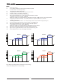
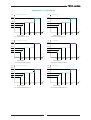
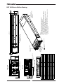
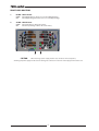
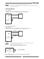
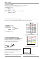
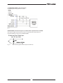
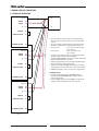
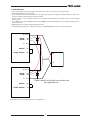
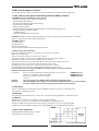
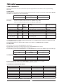
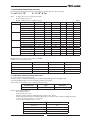
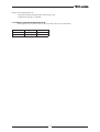
HFE1600/S (Optional PMBus) Series Instruction Manual. 1 2 3 4 5 6 7 8 9 10 11 12 13 14 15 16 17 18 19 20 21 22 23 24 25 26 27 28 29 30 31 32 33 34 35 36 37 38 39 40 41 42 43 44 45 46 47 48 49 50 51 52 HFE1600 SERIES SPECIFICATIONS: HFE1600-12/S HFE1600-24/S HFE1600-32/S HFE1600-48/S 12 24 32 48 12±1% 24±1% 32±1% 48±1% 9.6~13.2 19.2~29.0 25.6~38.4 38.4~58 (*1) 133 67 47 33 (*1) 100 50 37.5 25 (*1) Linear derating 1% per 1VAC from output current at 100VAC: 1596 1608 1500 1584 1200 1200 1200 1200 Linear derating 1% per V (*2) 85~265Vac continuous, 47~63Hz, Single phase 12.4/8.1 >0.99/0.98 87/90% 88/90% 88/90% (*3) 89/92% (*3) 87/90% 87/90% 87/90% 88/91% (*4) Less than 35A ≥ 10mS typical at 115/230Vac input, Hold-up time mS rated output voltage and less than 80% of rated load. 0.25% Maximum line regulation (*5) % Max load regulation (*6) % 0.50% mV 240 240 320 480 Output Ripple and noise P-P (*7) 0~+70°C -10~0°C mV 360 360 580 780 0.05% of rated Vout for 8hrs after 30min warm-up. Temperature stability % Constant line, load and temperature. ±200 Temperature coefficient of output voltage PPM/°C Remote sensing (*8) --Refer to instruction manual. Single wire current share, 5% accuracy of rated Iout, up to 10 units. Parallel operation (*9) --of the same voltage and the same current rating. Series operation --(with external diodes), 2 units. Refer to instruction manual. Minimum 105% of rated output current. Over current protection 85 ≤ Vin ≤ 132Vac % 105~120% of rated output current. 170 ≤ Vin ≤ 265Vac Tracking OVP, range: 1.1xVout ,Accuracy:±3%, Over voltage protection (*10) V Refer to Instruction Manual. Over temperature protection --Inverter shut down, automatic restart. Two complementary inputs. By electrical signal or dry contact. Remote On/Off control --Refer to instruction manual. Tracking, On when Vout>90±5% of set output voltage. "DC OK" signal (*13) --Open collector signal. Max sink current: 10 mA. Refer to instruction manual. Over-Temperature warning (*13) --Open collector signal. Max sink current: 10 mA. On when 85Vac<Vin<270Vac. "AC FAIL" signal (*13) --Open collector signal. Max sink current: 10 mA. Auxiliary power supply output (*11) --11.2~12.5V, 0.5A. 240mVp-p ripple and noise By 0~5V, equal to Vout min ~ Vout max . Refer to Instruction Manual. Vout programming by external voltage --Vout programming by external resistor --By 1Kohm potentiometer . Refer to Instruction Manual. Front panel indicators --AC OK, DC OK/FAIL I²C Interface --Optional, PMBus compatible. Refer to Instruction Manual. -10~+50°C. 100% load. Operating temperature (*14) --+50°C to +60°C Derate Output by 2%/°C. +60°C to +70°C Derate Output by 2.5%/°C. Storage temperature ---30~85°C Operating humidity --10~90% RH, no condensation. Storage humidity --10~95% RH, no condensation. By internal Fans. Variable speed control Cooling --based on ambient temperature and power level. Vibration --Built to meet IEC60068-2-64 (Basic Transportation) Shock --Built to meet IEC60068-2-27 (Basic Transportation) Built to meet EN55022 Class B, FCC part 15 Class-B, VCCI Class-B Conducted emission --Radiated emission --Built to meet EN55022 Class A, FCC part 15 Class-A, VCCI Class-A Built to meet IEC61000-4-2 (Level 2,3), -3 (Level 2), -4 (Level 2), Immunity ---5 (Level 3,4), -6 (Level 2), -8 (Level 4), -11 Applicable safety standards --UL60950-1 Second Edition, EN60950-1 Second Edition Input-Output: --3000Vrms, 1min. Withstand voltage Input-Ground: --2000Vrms, 1min. Output - Ground: --500VAC 1min. 500VAC 1min. 500VAC 1min. 2250VDC 1min (POE) Insulation resistance --More than 100MΩ at 25°C and 70% RH. Output-Ground: 500Vdc Leakage current (*12) mA Less Than 0.75/1.5mA at 115/230Vac range Weight (Typ) Kg Max. 1.55 Size (W*H*D) --85x41x300mm. Refer to Outline Drawing. Rated output voltage Output voltage set point Output voltage range Rated Output Current at Vin ≥ 170Vac Rated Output Current at 100 ≤ Vin ≤ 132Vac Rated Output Current at 85V ≤Vin < 100Vac Rated output power Vin ≥ 170Vac Rated output power 100 ≤ Vin ≤ 132Vac Rated output power 85Vac ≤ Vin < 100Vac Input voltage / frequency range Maximum input current (115/230Vac) Power Factor (Typ) (100/230Vac) at full load Efficiency at 75% rated load (Typ) Efficiency at 100% rated load (Typ) Inrush current V V V A A A W W W --A --% % A 1 Notes: *1 *2 *3 *4 *5 *6 *7 *8 *9 *10 *11 *12 *13 *14 Refer to Fig-1 below. In case where conformance to various safety standards is required, to be described as 100-240Vac (50/60Hz). 115/230Vac, 25˚C ambient temperature. Not applicable for the noise filter inrush current less than 0.2mS. From 85~132Vac, or 170~265Vac, constant load. From No-load to Rated load, constant input voltage. Measured with JEITA-RC9131A 1:1 probe with 2x270μF electrolytic capacitors and 1μF film capacitor on the output. 20MHz B.W. When power supplies are installed in HFE-1600-S1U shelf, measured with 1μF film capacitor on the output terminals. Voltage drop on load wires: HFE1600-12: 0.25V/wire, HFE1600-24: 0.5V/wire, HFE1600-32: 0.75V/wire, and HFE1600-48: 1V/wire. Accuracy applicable for load current > 50% of rated output current. Derate maximum output power by 5%. Inverter shut down method. Reset by recycle AC voltage, or by On/Off control. Measured with JEITA-RC9131A 1:1 probe using 470μF electrolytic capacitor and 0.1μF film capacitor on the output. 20MHz B.W. When power supplies are installed in HFE-1600-S1U shelf, capacitors not required. Measured according to UL/EN method at 60Hz 25˚C ambient temperature. Open collector signal. Maximum sink current: 10mA, maximum voltage 15V. Refer to Output Power vs temp derating figure A,B,C. (Pg. 3) Iout Iout HFE 1600-48 33A 1584W Max* 28A 21A 1504W Max* 39A 58V 1200W Max* 25A HFE 1600-32 47A 38.4~48V 1200W Max* 37.5A 1000W Max* 31.5A 17A 38.4~48V 25.6~32V 58V 38.4V 1000W Max* 26A Vin 85Vac 100Vac 132Vac 170Vac Vin 265Vac 85Vac Iout 132Vac 170Vac 265Vac Iout HFE 1600-24 67A 1608W Max* 56A HFE 1600-12 133A 19.2~24V 1596W Max* 121A 29V 1200W Max* 50A 42.5A 100Vac 1200W Max* 100A 1000W Max* 9.6~12V 13.2V 91A 34A 85A 1000W Max* 76A Vin 85Vac 100Vac 132Vac 170Vac Vin 265Vac 85Vac Fig-1 HFE1600 rated output Current and Voltage versus Line Voltage. * Please refer to Output Power vs. Temp derating 2 100Vac 132Vac 170Vac 265Vac Output Power vs. Temp derating Pout HFE 1600-12, 24,48 Series Pout 1600W 1500W 1200W 1200W 1100W 1100W 1000W 1000W HFE 1600-32 Vin 85Vac 100Vac 132Vac 170Vac Vin 265Vac 85Vac All Output Voltages Fig A. Output Power at temp -10~50°C. Pout 100Vac 132Vac 170Vac 265Vac 170Vac 265Vac All Output Voltages Fig A1. Output Power at temp -10~50°C. Pout HFE 1600-12, 24,48 Series 1280W 1200W 960W 960W 880W 880W 800W 800W HFE 1600-32 Vin 85Vac 100Vac 132Vac 170Vac Vin 265Vac 85Vac All Output Voltages Fig B. Output Power derating at temp 60°C. Pout 100Vac 132Vac All Output Voltages Fig B1. Output Power derating at temp 60°C. HFE 1600-12, 24,48 Series Pout 960W 900W 720W 720W 660W 660W 600W 600W HFE 1600-32 Vin 85Vac 100Vac 132Vac 170Vac Vin 265Vac 85Vac All Output Voltages Fig C. Output Power derating at temp 70°C. 100Vac 132Vac All Output Voltages Fig C1. Output Power derating at temp 70°C. 3 170Vac 265Vac 4 PIN No A1 ~ A5 A6 ~ A10 B1 B2 B3 B4 B5 B6 B7 B8 B9 B10 B11 PIN No B12 B13 B14 B15 B16 B17 B18 B19 B20 B21 C1 C2 C3 FUNCTION -V OUT +V OUT SIGNAL RETURN PS EXIST AUX_OUT (+12V) -SENSE A2 (PMBus) CURRENT SHARE ENABLE VOLTAGE ROGRAMMING +SENSE A3 (PMBUS) NC FUNCTION INHIBIT SCL (PMBus) A1 (PMBus) DC OK A0 (PMBus) SDA (PMBus) TEMP. ALARM V REFERENCE OUT SMB ALERT (PMBus) AC FAIL CHASSIS GROUND AC NEUTRAL AC LINE HFE 1600 Series Outline Drawing REAR PANEL IN/OUT CONNECTOR PINS FUNCTION DESCRIPTION Pin # Function A1 ~ A5 A6 ~ A10 -V +V B1 SIGNAL RETURN B2 PS EXIST B3 +12V AUX OUT B4 -SENSE B5,B10,B14,B16 A2,A3,A1,A0 (optional PMBus) B6 CURRENT SHARE B7 (short pin) ENABLE B8 VOLTAGE PROGRAMMING B9 +SENSE B11 B12 NOT CONNECTED INHIBIT SCL (optional PMBus) B13 B15 DC OK B17 SDA (optional PMBus) B18 TEMP ALARM B19 +5V/V_REF B20 SMB ALERT (optional PMBus) B21 AC FAIL C1 (long pin) C2 (long pin) C3 (long pin) PROTECTIVE GROUND AC NEUTRAL AC LINE Description Main Negative Output Voltage Main Positive Output Voltage Return for the following control signals: ENABLE, INHIBIT; supervisory signals TEMP ALARM, AC FAIL, AUX, DC OK, PS EXIST; and PMBus signals: SCL, SDA, SMB ALERT; SIGNAL RETURN and mentioned signals are isolated from the output terminals and -SENSE. Indicates that Power Supply module is inserted into the shelf. "Active Low" when connected to SIGNAL RETURN. 11.2~12.5V Auxiliary Voltage Output referenced to SIGNAL RETURN. The maximum load current is 0.5A. This output has a built in ORing diode, and is not affected by the INHIBIT /ENABLE signal or any other fault. Negative sense, The -SENSE signal should be connected to -V on Power Supply, or Load side. PMBus Address lines. Refer to the PMBus interface description HFE Instruction Manual Chapter 3. Current sharing signal should be connected when Power Supplies are connected in parallel to allow accurate current share between units in Parallel operation. Turns ON the main output by electrical signal or dry contact (0~0.6v or short). Input (0~5V) referenced to –S. Provides Vout programming by Voltage. Refer to Instruction Manual Chapter 1.5, 1.6 & 1.7 Positive sense. The +SENSE signal should be connected to +V on Power Supply, or Load side. Turns OFF the main output by electrical signal or dry contact (0~0.6v or short). Serial Clock signal. Refer to the PMBus interface description HFE Instruction Manual Chapter 3. DC OK signal. LOW when the output voltage is higher than 85~95% of set Vout. Open collector type (15V, 10mA). Serial Data signal. Refer to the PMBus interface description HFE Instruction Manual Chapter 3. TEMP ALARM signal. LOW when the internal temperature is within safe limit, HIGH approx. 10°C below Thermal shut down. Open collector type (15V, 10mA). 5V fix output for standard option unit. Variable when Voltage programming is done with PMBus option. Refer to Instruction Manual Chapter 3. PMBus INTERRUPT signal. Refer to the PMBus interface description HFE Instruction Manual Chapter 3. AC FAIL Signal, LOW when the input voltage is 85Vac<Vin<270Vac, HIGH when the input voltage is 85Vac>Vin or Vin>270Vac. Open collector type (15V, 10mA). AC GROUND connection. Refer to safety instructions for safety standards requirements AC NEUTRAL refer to safety instructions for safety standards requirements AC LINE refer to safety instructions for safety standards requirements. REAR CONNECTOR PIN ALLOCATION CHART A1 A5 A9 B1 B19 C1 A2 A6 A10 B3 C2 B21 IN/OUTPUT CONNECTOR POSITRONIC P/N: PCIM34W13M400A1/AA 5 C3 Referenced to SIGNAL RETURN SIGNAL RETURN SIGNAL RETURN -SENSE -SENSE -SENSE SIGNAL RETURN -SENSE -SENSE SIGNAL RETURN SIGNAL RETURN SIGNAL RETURN SIGNAL RETURN SIGNAL RETURN -SENSE SIGNAL RETURN SIGNAL RETURN FRONT PANEL INDICATORS 1. DC OK – LED indicator: 2. AC OK – LED indicator: GREEN RED GREEN OFF when Output Voltage is above 90% ± 5% of set Output Voltage. when Output Voltage falls below 90% ± 5% of set Output Voltage. when Input Voltage is 85Vac<Vin<270Vac; when the Input Voltage is 85Vac>Vin or Vin>270Vac; 2 1 CAUTION: When inserting a power supply into the rack, do not use unnecessary force; slamming the power supply into the rack can damage the connectors on the rear of the supply and inside the rack. 6 REGULATORY NOTICES CE NOTICE (European Union) Marking by the CE Symbol indicates compliance to the Low Voltage Directive (2006/95/EC) of the European Union. Such marking is indicative that the HFE1600-xy units meet the following technical standard: EN 60950-1:2006 - “Safety of Information Technology Equipment.” A “Declaration of Conformity” in accordance with the preceding directives and standards has been made and is on file at our EU representative TDK LAMBDA UK, located at Kingsley Avenue, Ilfracombe, Devon EX34 8ES, UK. SAFETY APPROVALS UL60950-1 Second Edition, UL Recognized, C-UL for Canada. IEC/EN 60950-1 Second Edition. CE marking, when applied to the HFE1600-xy units, indicates compliance with the Low Voltage Directive 2006/95/EC in that it complies with EN60950-1 Second Edition. SAFETY INSTRUCTIONS CAUTION: The following safety precaution must be observed during all phases of operation, service and repair of this equipment. Failure to comply with the safety precautions or warnings in this document violates safety standards of design, manufacture and intended use of this equipment and may impair the built-in protections within. TDK Lambda shall not be liable for user’s failure to comply with these requirements. Vorsicht Die folgenden Sicherheitsvorschriften müssen vor Inbetriebnahme und in jedem Betriebszustand bei Service oder Reparatur beachtet werden. Missachtung der Sicherheitsvorschriften und Warnhinweise aus diesem Handbuch führen zur Verletzung der bestehenden Sicherheitsstandards. Bei Betrieb des Gerätes ausserhalb dem bestimmungsgemässen Einsatz können die im Gerät integrierten Schutzfunktionen beeinträchtigt werden. TDK-Lambda ist nicht haftbar für Schäden, die durch Missachtung dieser Sicherheitsvorschriften entstehen können. CAUTION: HFE1600-xy units are not authorized for use as critical component in nuclear control systems, life support systems or equipment for use in hazardous environments without the express written approval of the managing director of TDK-Lambda. Vorsicht Dieses Produkt ist nicht für die Verwendung als kritische Komponente in nuklearen Steuerungssystemen, lebenserhaltenden Systemen oder Geräte für den Einsatz in gefährlichen Umgebungen, ohne die ausdrückliche schriftliche Genehmigung durch TDK-Lambda zugelassen POWER SYSTEM, OVERVOLTAGE CATEGORY & ENVIRONMENTAL CONDITIONS The HFE1600-xy units have been evaluated for using in TT and IT (230VAC line - to - line) power systems. The HFE1600-xy units have been evaluated to Overvoltage category II. The HFE1600-xy units intended for use in the following operation conditions: * Indoor use * Pollution degree 2 * Max. operational altitude: 3000m above sea level *Ambient temperature: -10°C-50°C at 100% load, up to 70°C with output de-rating applied (refer to Specification above). GROUNDING HFE1600-xy units are Class I product. To minimize electrical shock hazard, the HFE1600-xy units must be connected to an electrical ground. The instruments must be connected to the AC power supply mains through a three conductor power cable, with the ground wire firmly connected to an electrical ground (safety ground) at the power outlet. For instruments designed to be hardwired to the supply mains, the protective earth terminal must be connected to the safety electrical ground before any other connection is made. Any interruption of the protective ground conductor or disconnection of the protective earth terminal will cause a potential shock hazard that might cause personal injury. Erdungskonzept Dieses Produkt ist ein Gerät der Schutzklasse 1. Zur Vermeidung von gefährlichen Energieinhalten und Spannungen, ist das Gehäuse an eine Schutzerde anzuschliessen. Der PE-Anschluss ist an einen festen Erder anzuschliessen. Bei Festverdrahtung des Gerätes ist sicherzustellen, dass der PE Anschluss als erstes angeklemmt wird. Jede mögliche Unterbrechung des PE-Leiters oder Trennung der PE Verbindung kann einen möglichen elektrischen Schlag hervorrufen, der Personenschäden zur Folge hätte. LIVE CIRCUITS Operating personnel must not remove the HFE1600-xy unit cover. No internal adjustment or component replacement is allowed by non-TDK Lambda qualified service personnel. Never replace components with power cable connected. To avoid injuries, always disconnect power, discharge circuits and remove external voltage sources before touching components. Restricted Access Area: HFE1600-xy units should only be installed in a Restricted Access Area. Access should be available to service personnel only. Spannungsführende Teile Die Geräteabdeckung darf nicht durch Endanwender geöffnet werden. Interne Modifikationen, sowie Bauteileaustausch ist nur durch TDK-Lambda qualifiziertes Personal erlaubt. Vor Austausch von Bauteilen ist das Netzkabel bzw. die Versorgungsspannung zu trennen. Energieversorgungsanschlüsse sind immer zu trennen, um Personenschäden durch gefährliche Energieinhalte und Spannungen auszuschliessen. Die Stromkreise sind zu entladen, externe Spannungsquellen sind zu entfernen, bevor auf Bauteile bzw. Komponenten Ebene gearbeitet wird. 7 PARTS SUBSTITUTIONS & MODIFICATIONS Parts substitutions and modifications are authorized TDK Lambda service personnel only. For repairs or modifications, the instrument must be returned to TDK Lambda service facility. AC INPUT Do not connect HFE1600-xv unit to mains supply exceeding the input voltage and frequency rating. The input voltage and frequency rating is: 100-240V~, 50/60Hz. For safety reasons, the mains supply voltage fluctuations should not exceed ±10% of nominal voltage. HEAT HAZARD WARNING: Top, bottom and side surfaces may become hot when operating the unit continuously. To reduce the risk of injury from a hot surface, allow the surface to cool before touching. Heisse Oberflächen WARNUNG: Im Dauerbetrieb erwärmen sich die Gehäuseoberflächen. Um das Verletzungs-Risiko durch heisse Oberflächen zu minimieren, sollte das Gerät einige Zeit abkühlen können, bevor weitere Arbeiten durchgeführt werden. ENERGY HAZARD The main output of HFE1600-xy units is capable of providing hazardous energy. Due to hazardous energy level the output and connections therefore must not be user accessible. Manufacturer’s final equipment must provide protection to service personnel against inadvertent contact with output bus bars. FUSE Internal fuse is sized for fault protection and if a fuse was opened it would indicate that service is required. Fuse replacement should be made by qualified technical personnel. HFE1600-xy unit fuse rating is described below. F101: F20A H 250Vac SICHERUNGEN Vor Anschluss an die Netzversorgung ist die Aufstellanleitung zu beachten! 1. Absicherung: F1 01: F20A H 250VAC 2. Die Gehäuseabdeckung darf nur im stromlosen Zustand geöffnet werden. ACHTUNG: Sicherungen dürfen nur durch geschulte Service Personen getauscht werden. OVERCURRENT PROTECTION: A readily accessible branch circuit over-current protective device rated 30A max. must be incorporated in the building wiring. The protective device must be disconnect both supply line simultaneously Überstromschutz Eine leicht zugängliche Vorsicherung mit 30A max.. pro Eingang muss in der Hausinstallation vorgesehen werden SYMBOLS VORSICHT Spannungsführende Teile-Gefahr durch elektrischen Schlag bzw. Energieinhalte. Handbuch-Symbol. Das Gerät bzw. Geräteteile warden mit diesem Symbol gekennzeichnet, wenn es für den Benutzer notwendig ist, sich auf die Anweisungen im Handbuch zu beziehen. Zeigt “spannungsführende Teile” mit gefährlicher Spannung an. Dieses Symbol weist auf das Vorhandensein einer heißen Oberfläche oder Komponente. Das Berühren dieser Oberfläche kann zu Verletzungen führen. Zeigt Masse-Anschluss an, keine Schutzerde. ( z.B .Masseanschluss an einen Verbraucher). Schutzleiter-Anschlussklemme. WARNUNG Dieser Warnhinweis beschreibt Gefahren, deren Nichteinhaltung zu Personenschäden führen können. Die Warnhinweise müssen daher zwingend wie im Handbuch beschrieben in der Applikation eingehalten werden. ACHTUNG Diese Sicherheitsinformation weist auf Gefahren im täglichen Umgang mit dem Gerät hin, deren Missachtung zu Fehlfunktionen oder Defekten in deer Applikation führen können. Bitte lesen Sie diese Sicherheitsinformationen , bevor Sie das Gerät einbauen oder in Betrieb nehmen. 8 ATTENTION: Power supplies are factory programmed to the rated output voltage. For applications requiring lower/higher voltage, power supplies should be adjusted to the required voltage before connection to the load. 1. SINGLE UNIT OPERATION 1.1 Basic configuration (Local Sense) For basic configuration: •• ± SENSE have to be connected to the HFE1600 ±V terminals prior to operating the supply. •• ENABLE input must be connected to SIGNAL RETURN in order for the supply to turn on. HFE1600 +V A6~10 +SENSE -SENSE B9 B4 -V A1~5 ENABLE B7 SIGNAL RETURN B1 +V LOAD -V Fig-1.1 1.2 Basic configuration (Remote Sense) For basic configuration: •• ± SENSE have to be connected to the ±V terminals on the Load side prior to operating the supply. •• ENABLE input must be connected to SIGNAL RETURN in order for the supply to turn on. HFE1600 Voltage drop on load connection +V A6~10 +SENSE -SENSE B9 B4 -V A1~5 ENABLE B7 SIGNAL RETURN B1 +V LOAD -V Voltage drop on load connection Fig-1.2 ATTENTION: 1. 2. 3. Maximum voltage drop on load connection: HFE1600-12: 0.25V/wire, HFE1600-24: 0.5V/wire, HFE1600-32: 0.75V/wire, HFE1600-48: 1V/wire. Twisted wires should be used for Remote Sensing connection. If Remote Sensing is used, do not break Main Output connection. 1.3 ON/OFF control by ENABLE HFE1600 ENABLE B7 SIGNAL RETURN B1 Switch closed: Output ON Switch open: Output OFF Fig-1.3 SIGNAL RETURN and ENABLE control are isolated from the output terminals and “-SENSE”. 9 1.4 ON/OFF control by INHIBIT Power Supply operation requires the "ENABLE" signal to be connected to "Signal Return". Logic of the "INHIBIT" signal is reversed to logic of the "ENABLE" signal. Switch closed: Output OFF Switch open: Output ON Fig-1.4 SIGNAL RETURN, INHIBIT and ENABLE controls are isolated from the output terminals and -SENSE. 1.5. OUTPUT VOLTAGE PROGRAMMING by External Voltage. Output Voltage of HFE1600 Series can be programmed by external voltage source between approximately 80%-120% for 24V, 32V 48V and 80%-110% for 12V of nominal output voltage (For Output voltage limits see Graph enclosed). 58 HFE1600-48 38.4 HFE1600-32 29 HFE1600-24 HFE1600-12 13.2 Fig-1.5 Voltage Trimming by potentiometer V OUT (V) 59 60 1.6 OUTPUT VOLTAGE PROGRAMMING by External Potentiometer (Not Applicable to supplies with PMBus Option). Output Voltage of HFE1600 Series can be programmed by Potentiometer between approximately 80%-120% for 24V, 32V, 48V and 80%-110% for 12V of nominal output voltage (for limits see HFE1600 series specifications line 3). HFE1600 +5V/VREF 50 39.5 36 32 30 20 10 B19 48 40 0 B8 24 18 12 9.6 0% 50% Viper position Fig 1-5 Fig-1.6 HFE1600 1.7 OUTPUT VOLTAGE PROGRAMMING by PMBus (optional). Output Voltage of HFE1600 Series can be programmed by PMBus between approximately 80%-120% for 24V, 32V, 48V and 80%-110% for 12V of nominal output voltage (limits see HFE1600 series specifications line 3). +5V/ V REF B19 VOLTAGE PROG B8 Fig-1.7 ATTENTION: If PMBus is used for voltage programming, the Reference voltage will not be fixed to 5V but variable. 10 29 24 13.2 100% 1.8 SUPERVISORY SIGNALS (Typical Connection) The following supervisory signals are accessible: •• DC OK •• AC FAIL •• PS EXIST •• TEMP ALARM Fig-1.8 SIGNAL RETURN and mentioned signals are isolated from the output terminals and -SENSE. These signals are Open Collector type (max 15V, max 10mA) shunted by internal 24V zener, isolated from Output and referenced to “SIGNAL RETURN”. Fig-1.9 Open collector signals are shunted by internal 24V zener 11 2. POWER SUPPLIES CONNECTION 2.1. PARALLEL OPERATION HFE1600 +V A6~10 +SENSE -SENSE B9 B4 -V A1~5 ENABLE B7 SIGNAL RETURN B1 CURRENT SHARE HFE1600 -S •• Up to 10 x HFE1600 units with the same rating (voltage and current) can be used in parallel to increase the output current. •• By connecting the CS signal between the paralleled units, automatic current balance is achieved with accuracy of Accuracy ±10%: 20% ≤ Iout < 50% of max Iout. Up to 10 units Accuracy ±5%: Iout ≥ 50% of max Iout. Up to 10 units •• Derate the total output current by 5% when using parallel operation to prevent unit overload condition. •• The built-in ORing MOSFETs on the main output and the 12V Auxiliary output allow N+1 operation. •• If Voltage programming is used, “Voltage Programming” Pin of all units must be connected in parallel. •• Referenced to “SIGNAL RETURN” (floating from the output) controls/signals and +12V AUX can be connected in parallel. •• ENABLE of all supplies can be connected to a single switch. +V A6~10 B9 B4 -V A1~5 ENABLE B7 SIGNAL RETURN B1 CURRENT SHARE For PMBus option. •• If voltage programming is done with PMBus, Voltage Programming and VREFERENCE OUT of all units must be connected in parallel. •• Connect PMBus Signals in parallel (PMBUS is isolated from output), and choose different address for each unit. B6 +V A6~10 +SENSE -SENSE B9 B4 -V A1~5 ENABLE B7 SIGNAL RETURN B1 CURRENT SHARE B6 LOAD -V B6 +SENSE -SENSE HFE1600 +V +S Fig-2.1 12 2.2 SERIES OPERATION •• Up to 2 units with the same rating (voltage and current) can be used in series to increase the output voltage. •• Connect Main Output in series (as shown). •• Diodes should be connected in parallel with each unit output to prevent reverse voltage. Each diode should be rated to at least the power supply rated output voltage and output current. •• Connect as shown : +Sense of positive unit and –Sense of negative unit (twisted pair) to Load point, or to +V and –V accordingly for Local Sense. •• In case PMBus is used, Connect PMBus signals in parallel (PMBus is isolated from Output), and choose different address for each unit (see chapter 3). •• Output Voltage can be adjusted independently for each unit. •• Controls Monitoring signals and +12V AUX are referenced to “SIGNAL RETURN” and may be connected in parallel. HFE1600 +V A6~10 +SENSE -SENSE B9 B4 -V A1~5 ENABLE B7 SIGNAL RETURN B1 +V LOAD -V HFE1600 +V A6~10 +SENSE -SENSE B9 B4 -V A1~5 ENABLE B7 SIGNAL RETURN B1 * Diodes rated to at least Vout max and lout max are supplied by user Fig 2.2 HFE1600 series connection (remote sense configuration) 13 3. PMBus Interface Option ( /S Option ) HFE1600 SERIES I2C SPECIFICATIONS: 1. FEATURES 1.1 Output voltage measurement. 1.2 Output voltage programming. 1.3 Output current measurement. 1.4 Internal ambient temperature measurement. 1.5 Product information 1.6 Status information 1.7 SMBus alert 1.8 Clock frequency: 100KHz 1.9 Address lines: 4 1. OUTPUT VOLTAGE MEASUREMENT 1.1 Measurement accuracy 1.2 Measurement resolution 1.3 Measurement range (Full Scale) V +/-2% of full scale. Refer to instruction manual 10 bit 0~30 0~40 0~60 0~15 2. OUTPUT VOLTAGE PROGRAMMING 2.1 Programming accuracy 2.2 Programming resolution 2.3 Programming range V HFE1600-12/SHFE1600-24/SHFE1600-32/SHFE1600-48/S +/-2% of full scale 10 bit 19.2~29.0 28.8~38.4 38.4~58 9.6~13.2 3. OUTPUT CURRENT MEASUREMENT 3.1 Measurement accuracy 3.2 Measurement resolution 3.3 Measurement range (Full Scale) A HFE1600-12/SHFE1600-24/SHFE1600-32/SHFE1600-48/S +/-10% of full scale 10 bit 0~80 0~60 0~40 0~160 - HFE1600-12/S HFE1600-24/S HFE1600-32/S HFE1600-48/S 4. INTERNAL AMBIENT TEMPERATURE MEASUREMENT (refer to Instruction Manual) 4.1 Measurement device accuracy ±3°C. 4.2 Measurement resolution 10 bit °C 4.3 Measurement range 0~100 5.PRODUCT INFORMATION - Factory programmed 5.2 Model Name 5.3 Revision - Factory programmed - Factory programmed 5.4 Serial Number - Factory programmed 5.5 Manufacturing location - Factory programmed 5.6 Coefficients 5.7 Date of Manufacture - Factory programmed - Factory programmed 5.8 Nominal Output - Factory programmed 5.1 Product ID 6.STATUS INFORMATION 6.1 "FAN FAIL" Signal 6.2 "DC FAIL" Signal 6.3 Output "OVP" Signal 6.4 "TEMPERATURE ALARM" signal 6.5 "OTP" Signal 6.6 "AC FAIL" Signal 6.7 I2C ON/OFF control 6.8 "SMB ALERT" signal "1" -FAIL, "0"-OK "1" -FAIL, "0"-OK "1"- OVP, "0"-OK "1"- ALARM, "0"-OK "1" -OTP, "0"-OK "1" -FAIL, "0"-OK "1" -ON, "0"-OFF "1" -OK, "0"-ALERT 14 3. PMBus Interface Option ( /S Option ) The communications bus signals are powered by an external 3.3V power source pulled up with a 1.5kΩ resistor 3.1 HFE_1600 may have optional Power Management Bus (PMBus) hardware. The PMBUS interface in the HFE1600 (/S option) includes: •• Monitoring the Output Voltage, Current and Temperature •• Programming the Output Voltage •• Programming the Maximum allowed output Voltage •• Programming the Supply On/OFF. •• Reading and Clearing Faults. •• Reading the Manufacturing Related Data (Model Name, Serial No, Manufacturing Date, etc) •• Storing the following conditions at AC Off - Set Output voltage - Max allowed programmable output voltage ATTENTION: If PMBus is used for voltage programming, the reference voltage will not be fixed to 5V but can be variable. (Reference voltage will be used for voltage programming). The PMBUS supports: 100KHz Operation. Block Read Protocol Group Command Protocol Direct Data Format for Monitoring and Programming Functions 3.2 Addressing (A3, A2, A1, A0 inputs) Four variable address lines allow up to 16 Supplies to be connected on a single bus. PMBus uses 7 bit addressing. There is constant part of address and variable part of address: Constant part of address consists of 3 Most Significant Bits A6, A5, A4 and always equals 001. Variable part of address consists of 4 Least Significant bits: A3, A2, A1, A0. Value of these four bits have to be assigned by hardware connections of 4 pins of the PS connectors. The Address lines (A3, A2, A1, A0) are internally pulled up by resistors to +5V. The address lines can be left open for ‹1› address or connected to -S for ‹0› address. So, available Address Space contains 16 possible addresses: from 0010000 to 0011111. In case more than one unit is connected to PMBus, each unit must be set to its own unique address. Duplicate addressing is not allowed. For example: Attention: Hot Plug: first unit -- A3(J1.B10), A2(J1.B5), A1(J1.B14), A0(J1.B16) are not connected – ADDRESS 0011111; second unit -- A0(J1.B16) is connected to -SENSE – ADDRESS 0011110; third unit – A1(J1.B14) is connected to -SENSE – ADDRESS 0011101; and so on. A3, A2, A1, A0 signals and -SENSE are NOT isolated from the Output Terminals. When hot plugging a power supply into a live system, the supply takes about 1-2 seconds to configure its address on the bus (based on the analog voltage levels present on the back plane). 3.3 SERIAL CLOCK This line is clocked by the Controller which controls the PMBUS. It should be connected to +3.3V (referenced to “Signal RTN”) via a 1.5kΩ pull-up resistor. 3.4 SERIAL DATA This is a Bi-Directional line which must be connected to +3.3V (referenced to Signal RTN) via a 1.5kΩ pull up resistor. 3.5 SMBALERT SMBALERT is used to indicate to the HOST about any Faults/Error Conditions. This line must be connected to +3.3V (referenced to Signal RTN) via a 1.5kΩ pull up resistor. This Signal is HIGH to indicate that no fault/error is present. If some fault/error occurs, the signal will go LOW. The Host system must poll multiple supplies after receiving SMBALERT to retrieve fault/warning information. 3.6 PMBus TYPICAL CONNECTION “SIGNAL RETURN” and PMBus signals are isolated from the Output terminals and Senses. Fig-3.6 PMBus Typical connection 15 4. PMBus COMMAND SET The interval between two consecutive commands to the power supply should be at least 25ms to ensure proper monitoring functunality. 4.1 READ_STATUS This Command is used to read the status of the Power Supply. The Status information is stored in a special register called the “STATUS REGISTER”. The PMBUS reads 8 different types of Faults and Warnings. Command Used Type #Data bytes D0h Read Byte 1 Fault is indicated by “1”. No fault is indicated by ”0”. For Example: If DC Fail occurs, READ_STATUS will return 01h. SMBALERT will go “LOW” If AC Fail occurs, READ_STATUS will return 11h. SMBALERT will go “LOW” Faults Type DC Fail Over Temperature Protection Over Temperature Alarm Fan Fail AC Fail Over Voltage Protection Programmed Voltage more than allowed Command Error FAULT FAULT WARNING FAULT FAULT FAULT WARNING WARNING Bit No in Status Register 0 1 2 3 4 5 6 7 Meaning Main output behavior Output Voltage < 85~95% of Set Vout Internal temperature higher than safe limit Internal temperature ~ 10°C below safe limit. One or both Fans are not working Input Voltage <85Vac / >270Vac Output Voltage > 1.15xVset Programmed Voltage more than Max Allowed Voltage (*1) Command not understood by Power Supply (*2) Output OFF/Output Low Output OFF Output ON Output OFF Output OFF/Output ON Output OFF Output ON Output ON (*1) If Max Allowed Voltage is set to 48V and Programmed Voltage is set to 50V, Output will be programmed to 48V, Bit No 6 will be “1”, and SMBALERT will become “LOW”. (*2) If any Command sent is not understood by the Supply, bit no 7 will be “1” and SMBALERT will become “LOW”. 4.2 CLEAR_FAULTS This command is used to clear the “STATUS REGISTER” after any fault occurs. If the CLEAR_FAULTS command is not sent after any fault occurs, the “STATUS REGISTER” will not be cleared. SMBALERT signal will remain “LOW” until a “CLEAR_FAULTS” command is sent. If a Fault or Warning is still present after “CLEAR_FAULTS” is sent, “STATUS REGISTER” will be updated and the SMBALERT signal will be “LOW” again. Command code Type #Data bytes 03h Send Byte 0 Command code Type Data sent 01h 01h R/W Byte R/W Byte 00h=OFF 80h=ON 4.3 OPERATION (ON/OFF) If the Power Supply is turned OFF with the “OPERATION OFF” command, the Supply can be turned ON with the “OPERATION ON” command only. Inhibit and Enable signals are disabled. 4.4 COMMANDS TO READ INVENTORY DETAILS Command Name PMBUS_REVISION MFR_ID MFR_MODEL MFR_OUTPUT MFR_REVISION MFR_LOCATION MFR_DATE MFR_SERIAL Command code Type #Data bytes 98h 99h 9Ah D1h 9Bh 9Ch 9Dh 9Eh Read Byte Read Block Read Block Read Block Read Block Read Block Read Block Read Block 1 16 16 16 16 16 16 20 All details except for ‹PMBUS_REVISION› are stored in ASCII format. 16 4.5 PROGRAMMING AND MONITORING FUNCTIONS For Monitoring and Programming functions use the following equation. This is the direct data format. Y = (mX + b )* 10R Where - X = (Y*10 R- b )/m Y - digital value sent or received from the supply. X is the normal value (V, A, °C) m, b, R - coefficients that are explained in Table 1. Table 1 Voltage (V) Physical value Physical Unit Min. Value Max. Value m b R 48 Voltage Programming Voltage monitoring Current monitoring Temperature monitoring Voltage Programming Voltage monitoring Current monitoring Temperature monitoring Voltage Programming Voltage monitoring Current monitoring Temperature monitoring Voltage Programming Voltage monitoring Current monitoring Temperature monitoring V V A °C V V A °C V V A °C V V A °C 38.4 0 0 0 28.8 0 0 0 19.2 0 0 0 9.6 0 0 0 58 60 40 100 38.4 40 60 100 29 30 80 100 13.2 15 160 100 426 1705 25575 1023 639 25575 1705 1023 853 341 12787 1023 1705 682 6394 1023 -15335 0 0 0 -15333 0 0 0 -15360 0 0 0 -15345 0 0 0 -1 -2 -3 -2 -1 -3 -2 -2 -1 -1 -3 -2 -1 -1 -3 -2 32 24 12 m, b, R coefficients can also be recovered from the EEPROM coefficients are stored in ASCII Format Command name Command code Type #Data bytes MFR_VOLTAGE_MON_COEFF D2h Read Block 16 MFR_CURRENT_MON _COEFF D3h Read Block 16 MFR_TEMP_MON_COEFF D4h Read Block 16 MFR_VOLTAGE PROG_COEFF D5h Read Block 17 4.5.1 MONITORING THE OUTPUT VOLTAGE (READ_VOUT) The accuracy of the voltage reading is +/-2% The output voltage is read before the ORING Circuit (~50mV Voltage drop @ load, no drop @no load). The read back Output Voltage can be calculated using the “Direct data Format”. Refer to Table 1 for the Coefficients for calculating the Output Voltage. Command code Type #Data bytes 8Bh Read Word 2 Example: Power Supply HFE1600-48; Hex read back = 032Ch; Converted to Decimal = 812; Using the required coefficients the Output Voltage 812x100/1705 = 47.62V. Read the Actual Output Voltage on the Output Bus Bar (Ex: 47.90V). Add 0.05V to compensate ORing Circuit drop So, the actual voltage is (Ex: 47.90 + 0.05 = 47.95V). Accuracy is (47.95-47.62)/60(*1)x100 = 0.55% Supply (*1) Full Scale (*1) HFE1600-12 15V HFE1600-24 30V HFE1600-32 40V HFE1600-48 60V 17 4.5.2 MONITORING THE OUTPUT CURRENT (READ_IOUT) The accuracy of the current reading is +/-10% The read back output current can be calculated using the “Direct data Format”. Refer to Table 1 for the Coefficients for calculating the Output Current. Command Used Type #Data bytes 8Ch Read Word 2 Example: Hex read back = 0361h; Converted to Decimal = 865; Using the required coefficients the output current = 865x1000/25575 = 33.82A; Read the actual Output current (Ex: 33.05A) / Accuracy is (33.05-33.82)/40(*1)x100 = -1.92% Supply (*1) Full Scale (*1) Supply (*1) Full Scale (*1) HFE1600-12 HFE1600-24 160A 80A HFE1600-32 HFE1600-48 60A 40A 4.5.3 MONITORING THE SUPPLY TEMPERATURE (READ_TEMPERATURE_1) The accuracy of the Temperature reading is +/-5oC The read back supply temperature can be calculated using the “Direct data Format”. Please refer to table 1 for the Coefficients for calculating the Supply Temperature Command Used Type #Data bytes 8Dh Read Word 2 Example: Hex read back = 01DCh; Converted to Decimal = 476; Using the required coefficients the Supply Internal Temperature = 476*100/1023 = 46.53°C. 4.5.4 PROGRAMMING THE OUTPUT VOLTAGE (VOUT_COMMAND) The accuracy of the Output Voltage Programming is +/-2% The output Voltage can be programmed using the “Direct data Format”. Please refer to table 1 for the Coefficients to be used for calculating the Voltage Programming. Command Used Type #Data bytes 21h R/W Word 2 Example: Power Supply HFE1600-24; To program the Output Voltage to 24V, send (853x24+(-15360))/10 = 511 (DEC); Read the actual set output Voltage (Ex: 24.05V) / Accuracy is (24.05-24)/30(*1)x100 = 0.16% Supply (*1) Full Scale (*1) Supply (*1) Full Scale (*1) HFE1600-12 HFE1600-24 15V 30V HFE1600-32 HFE1600-48 40V 60V 4.5.5 PROGRAMMING THE MAXIMUM ALLOWED PROGRAMMABLE OUTPUT VOLTAGE (VOUT_MAX) The output Voltage can be programmed using the “Direct data Format”. Please refer to table 1 for the Coefficients to be used for calculating the Voltage Programming. Command Used Type #Data bytes 24h R/W Word 2 18 Example: Power Supply HFE1600-24; To program the maximum programmable output voltage to 29V Send (853x29+(-15360))/10 = 938 (DEC) 4.5.6 ENABLING / DISABLING THE MONITORING FILTER Monitoring filter can be enabled in order to reduce the effect of noise on the readback data. Command Used Type Data sent D6h D6h R/W Byte R/W Byte 00h=OFF 01h=ON 19 IA688-04-01S/E 20