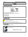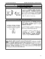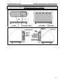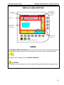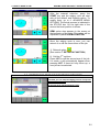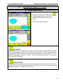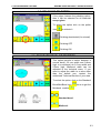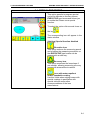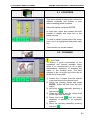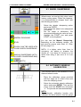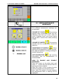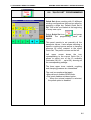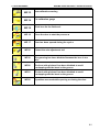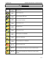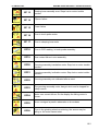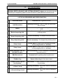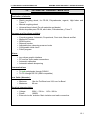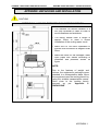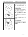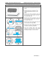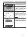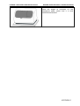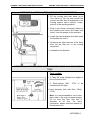
1
MAXIMA SPEED
OPTIMA
edger
edger
User’s manual
2238-0102_10-08_English
Dear customer,
INDUSTRIAS DE OPTICA S.A.U. is grateful for your reliance on its product.
You have purchased high quality equipment that will provide you great professional
satisfaction.
As a contribution to this, we include the following user’s manual, with all the
necessary information for proper use of the equipment.
READ THIS MANUAL BEFORE USE
•
This User’s Manual contains necessary information for the operation of the OPTIMA
ADVANCE and MAXIMA SPEED ADVANCE edger.
•
This manual provides all available operating procedures and options, use and safety
measures, accessories information, basic maintenance and technical specifications.
•
Before using for the first time the edger, a complete reading and understanding of
its content is required, in particular operations procedure and safety cautions.
•
Keep this manual close to the equipment and read it if needed.
•
If you have any question or find any problem about the equipment during operation,
please contact the INDO’s authorised Technical Service in your area.
INDEX
A. SAFETY
A.1
B. CAUTIONS FOR THE INSTALLATION AND USE
B.1
C. USE WARNINGS
C.1
D. WASTE AND DISPOSAL
D.1
E. LABELS
E.1
1.
PRODUCT INTRODUCTION
1.1
2.
SYSTEM CONFIGURATION
2.1
2.1
SINGLE CONNECTION
2.1
2.2
NETWORK CONNECTION
2.1
3.
DESCRIPTION OF PARTS
3.1
4.
DESCRIPTION OF PROCESSES
4.1
5.
6.
7.
4.1
COMPULSORY PROCESSES
4.1
4.2
OPTIONAL PROCESSES
4.2
HOW TO MAKE A JOB
5.1
5.1
OVERVIEW
5.1
5.2
EMERGENCY STOP OF THE EDGING PROCESS
5.2
ADVANCED MENU OPTIONS
6.1
6.1
BEVEL SELECTION
6.1
6.2
POLISHING SELECTION
6.3
6.3
STANDARD BEVEL OR MINIBEVEL
6.3
6.4
SPECIAL PROCESSES
6.4
6.5
ROUGHING TYPE
6.5
6.6
HOW TO CALL A “QUICKSET”
6.6
6.7
THE “SEMI” FUNCTION
6.7
6.7.1
HOW TO ACTIVATE THE “SEMI” FUNCTION
6.7
6.7.2
HOW TO USE THE SEMI FUNCTION
6.8
6.7.3
MANUAL BEVEL
6.8
RETOUCH FUNCTION
7.1
INDEX
8.
TECHNICAL MENU FOR USERS
8.1
8.1
COUNTERS
8.2
8.2
CLEANING
8.2
8.3
WHEEL SHARPENING
8.4
8.4
AUTOMATIC WHEELS CALIBRATION
8.4
8.5
USER MAINTENANCE WARNINGS
8.5
8.6
“QUICK SET” PROGRAMMING
8.6
8.7
TOUCH PROBES CALIBRATION
8.7
8.8
BEVEL POSITION ADJUSTMENT AND BEVELLED LENSES SIZE
AJUSTMENT
8.8
8.9
GROOVE AND PIN-BEVEL POSITION ADJUSTMENT AND GROOVED
LENSES SIZE ADJUSTMENT
8.9
9.
USER WARNINGS
9.1
10.
ERROR LIST
10.1
11.
MAINTENANCE AND GENERAL CARE
11.1
11.1
GENERAL MAINTENANCE
11.1
11.2
FUSE REPLACEMENT
11.2
12.
ACCESSORIES
12.1
13.
TECHNICAL CHARACTERISTICS
13.1
APPENDIX.
UNPACKING AND INSTALLATION
1
APPENDIX 1.
HOW TO PREPARE THE WORKING BENCH
1
APPENDIX 2.
UNPACKING
2
APPENDIX 3.
HOW TO REMOVE THE TRANSPORTATION LOCKS
3
APPENDIX 4.
HOW TO INSTALL THE SOUNDPROOF BASE
4
APPENDIX 5.
INSTALLATION OF THE COOLING CIRCUIT
6
APPENDIX 6.
INSTALLATION WITH DIRECT WATER AND DECANTER TANK
6
INDEX
A. SAFETY
MAXIMA SPEED ADVANCE / OPTIMA ADVANCE
A. SAFETY
IN THIS MANUAL, A SIGNAL WORD IS USED TO DESIGNATE THE DEGREE OR
LEVEL OF SAFETY ALERTING.
THERE ARE 2 TYPES OF LABELS DEPENDING ON THE SAFETY LEVEL.
CAUTION!
•
Indicates a potentially hazardous situation which, if not avoided, may result in minor or
moderate injury or a property damage accident.
WARNING!
•
Indicates a potentially hazardous situation which, if not avoided, could result in
death or serious injury.
Even situations that are labeled
CAUTION! may result in serious injury under
certain situations. Safety precautions must be followed strictly at all times.
FOLLOWING THE RECOMMENDATIONS AND SAFETY RULES DESCRIBED IN THIS
MANUAL IS VERY IMPORTANT.
A.1
B. CAUTIONS FOR THE INSTALLATION AND USE
MAXIMA SPEED ADVANCE / OPTIMA ADVANCE
B. CAUTIONS FOR THE INSTALLATION AND USE
WARNING!
•
Do not place the equipment over the power cord. Cord cover may be damaged and
cause electrical shocks or short-circuits.
•
If metal wires of the cord are exposed, power turns off and on when moving cord or
cable/plug are abnormally hot, that means cable is damaged. Immediately change the
cable by a new one. If not, it may result in electrical shock or fire.
•
The MAXIMA SPEED ADVANCE / OPTIMA ADVANCE edgers should be installed in
a stable and well-leveled place, free of shocks or vibrations. If not, it may result in poor
final quality of the jobs or equipment malfunction.
•
In case of a direct water connection, the water inlet should be protected through an
external tap installed in the water supply pipe. Input flow and pressure should not
exceed the normal values of a domestic water network.
•
In case of a direct water connection, the draining pipe should remain at least ½ meter
below the machine level. The draining hose should connect to the draining pipe without
angles that make difficult the evacuation of remains.
B.1
C. USE WARNINGS
MAXIMA SPEED ADVANCE / OPTIMA ADVANCE
C. USE WARNINGS
WARNING!
• Never disassemble nor touch the internal structure of the edger. Electric shock or failure of
the instrument may occur.
• Never use the equipment for purposes other than the specified. INDUSTRIAS DE
ÓPTICA S.A. will not be responsible for accidents or malfunctioning caused by this wrong
use.
• Use equipment in the following conditions:
-
Equipment for indoor use.
Temperature: 5ºC - 40ºC
Relative humidity: max. 80% up to 31ºC, with linear decrease up to 50% at 40ºC
Altitude: 2000 m
Accepted mains fluctuations: ± 10%
Installation category: II
Pollution degree: 2
Interferences, vibration and shock free environment
Power inlet with ground connection.
• For the storage of the packed equipment and its shipment we recommend the same
conditions of temperature and humidity.
• Operator's working location is in front of the edger, facing the working area, this last being
protected with the main cover. Working area is described as the part of the unit containing
the grinding wheels and lens shafts. Danger area is the part of the working area
between grinding wheels and lens shafts.
• NEVER manipulate inside the working area while lens is being edged. Manipulation is
only permitted when the cycle has reached its end and grinding wheels have completely
stopped its rotation. When the cycle starts, close the cover manually so that the working
area stays protected, not being accessible. NEVER OPEN THE COVER DURING A
WORKING CYCLE. If, due to use reasons, the said cover should be opened, then
AVOID ANY USER’S OR THIRD PERSON’S MANIPULATION INSIDE THE WORKING
AREA.
• With the main cover closed, noise and acoustic pressure levels are tolerable. Special
protection elements are not needed.
• In case of malfunction, never touch inside the equipment. Remove power cord and contact
with INDO’s authorised Technical Service in your area.
C.1
D. WASTE AND DISPOSAL
MAXIMA SPEED ADVANCE / OPTIMA ADVANCE
D. WASTE AND DISPOSAL
D.1 DRAIN FILTERS
CAUTION!
•
For correct edged lenses waste disposal make sure to use recommended mode and
type drain filters, otherwise drainpipes may get stuck.
•
Filters must be cleaned on a regular basis or changed as often as needed by the kinds
of edged materials and lenses number.
D.2 WASTE AND DISPOSAL ORDINANCES
•
Follow local governing ordinances and recycling plans regarding disposal or
recycling of device components.
•
When disposal of packing material follow local governing ordinances according to
your classification.
•
When disposing of lens waste, follow local governing ordinances.
D.3 WASTE AND DISPOSAL LABEL
•
This sign shows that this device needs a selective wasting program in order to have a
correct environment management and must never be disposed of when not used.
You’ll see on the edger an ID label with crossed garbage container as shown on
picture. This tag shows that the machine disposal must be sorted by material for
environmental care and can’t be disposed of improperly.
NOTA:
Independently from the actual local governing ordinances, INDO, through its
Corporative Social Responsibility commitment, has adhered voluntarily to the
United Nations World Pact (Global Compact) and works for the sustainable
development and to reduce the environmental impact in its activities, having set an
Environment Management System based on the International Standards ISO 14001
from 2001.
D.1
E. LABELS
MAXIMA SPEED ADVANCE / OPTIMA ADVANCE
E. LABELS
E.1 IDENTIFICATION LABEL
Equipment ID label on the right side of the machine:
This tag shows the following main data:
• Type of edger (Maxima Speed Advance or Optima Advance)
• Edger serial number
• Power voltage (V)
• Machine power (W)
• Power frequency (Hz)
E.2 HAZARD LABEL
Label on the sink water output.
Hazard if handling in this area when the wheels are rotating.
Please apply strictly all safety recommendations described in this manual.
E.3 FUSE LABEL
(For cooling unit and electrovalves)
Placed on the left side of the edger and at the side of each cooling unit
or electrovalve output.
•
•
FUSES for 220V-240V = 2 A slow
FUSES for 110V-120V = 3 A slow
E.1
1. PRODUCT INTRODUCTION
1.
MAXIMA SPEED ADVANCE / OPTIMA ADVANCE
PRODUCT INTRODUCTION
• The MAXIMA SPEED ADVANCE / OPTIMA ADVANCE edger represents the
evolution of the previous MAXIMA SPEED / OPTIMA EVOLUTION model within
our range of INDO’s new generation systems for ophthalmic lens edging.
• Edging different types of material:
-
MINERAL
CR39
HIGH INDEX ORGANIC
POLYCARBONATE
TRIVEX™
• Lens finishing with:
-
Standard bevel
Minibevel
Flat bevel
• As extra functions it allows:
-
Internal and external pin bevel
Grooving function (all material except mineral)
Polishing (all material except mineral)
• The MAXIMA SPEED ADVANCE / OPTIMA ADVANCE edger uses the 3D digital
technology to calculate and trace the lens bevel. The display shows the bevel
tracing and the lens thickness during the edging process.
• Through its display and using a simple icon-based user menu the edger functions
can be easily controlled.
1.1
2. SYSTEM CONFIGURATION
2.
MAXIMA SPEED ADVANCE / OPTIMA ADVANCE
SYSTEM CONFIGURATION
2.1 SINGLE CONNECTION
To connect the MAXIMA SPEED ADVANCE /
OPTIMA ADVANCE – COMBIMAX ADVANCE
system in single mode, connect the edger to the
tracer with the communication cable 2114/482
(C28), supplied with the COMBIMAX ADVANCE.
Note: The cable is 3 meter long
2.2 NETWORK CONNECTION
For high productions, the OPTIMA ADVANCE
system allows a network connection, linking
several OPTIMA ADVANCE edgers to a single
COMBIMAX ADVANCE.
It is recommended to connect a maximum of 3
edgers to a single peripheral, so that the duty
cycle of every unit will remain balanced.
To establish a network of edgers with one
peripheral, it is required a Network
connection Kit. It links up to 3 MAXIMA
SPEED ADVANCE / OPTIMA ADVANCE
edgers to a single COMBIMAX ADVANCE.
NOTE: MAXIMA SPEED ADVANCE AND OPTIMA ADVANCE edgers are compatible
with the former INDO generation of peripherals. Therefore, it is possible to install a
network with MAXIMA SPEED ADVANCE / OPTIMA ADVANCE edgers connected to a
SERVICE MODULE, INDOFORM CNC, CNC or MINIBLOC, sharing the net with an
ELITE XXI, LINEA XXI, MAXIMA and OPTIMA edgers. However, the MAXIMA SPEED
ADVANCE / OPTIMA ADVANCE edgers don’t communicate with the 10-job Memory
Box, sometimes used with the INDOFORM CNC.
2.1
3. DESCRIPTION OF PARTS
3.
MAXIMA SPEED ADVANCE / OPTIMA ADVANCE
DESCRIPTION OF PARTS
3.1
3. DESCRIPTION OF PARTS
MAXIMA SPEED ADVANCE / OPTIMA ADVANCE
DISPLAY AND KEYPAD
Lens clamping
pressure and
pressure against
the wheels
Process
description
Status box
Lens edging
process
visualization
Lens edging
settings
STOP
START
CLOSE/OPEN Clamp
DOOR
The MAXIMA SPEED ADVANCE features an automatic door that closes at the beginning
of the cycle and opens at the end. You can open it or close it at any time pressing the
key
.
This option is not available on the OPTIMA ADVANCE.
CAUTION!
If you open the door during the cycle, the edger will stop immediately the edging process.
3.2
4. DESCRIPTION OF PROCESSES
4.
MAXIMA SPEED ADVANCE / OPTIMA ADVANCE
DESCRIPTION OF PROCESSES
The MAXIMA SPEED ADVANCE / OPTIMA ADVANCE edger makes a standard job
in 3 basic steps: MEASURING STEP, ROUGHING STEP and FINISHING STEP.
These processes can be completed by other options: POLISHING, GROOVING and
PIN BEVELLING.
4.1 COMPULSORY PROCESSES
1st process: Measuring step
The cycle is starting with a measuring
process where the lens thickness is
measured according to the frame shape and
the base where will be edged the bevel. Both
arms of the touch probe assembly make
contact with internal and front side to map
the lens.
Arm tips are made of plastic and do not
scratch the lenses. However, if covered with
glass dirt, they can scratch, although they
will do it in the borderline of material
removal. Therefore, it is recommended to
clean arm tips on a daily basis.
2nd process: Roughing step
Once measurement step has finished, the
lens moves down over the roughing wheel,
following selected process (see Roughing
selection). This operation removes the
excess of material, giving to the lens the
required shape and size, so that selected
bevel can be edged.
3rd process: Finishing step
Finishing step is the final step, in which
selected bevel is edged.
( Bevel, Minibevel and Flat bevel)
4.1
4. DESCRIPTION OF PROCESSES
MAXIMA SPEED ADVANCE / OPTIMA ADVANCE
4.2 OPTIONAL PROCESSES
THE OPTIONAL PROCESSES DESCRIBED AS FOLLOW (POLISHING,
GROOVING AND PIN BEVELLING) COMPLETE THE COMPULSORY ONES.
• POLISHING PROCESS:
Option allowing polishing for plastic lenses.
Polishing ON
NOTE: This option is not available for mineral
lenses.
Polishing OFF
Grooving
current depth
and width
•
GROOVING PROCESS:
WARNING: The minimum lens
thickness to groove is 1.5 mm.
MINERAL
LENSES
CAN
NOT
BE
GROOVED. RISK OF GROOVING DISC
DAMAGE.
Automatic grooving
For minus lenses, the groove will be parallel to
the front side for thickness bigger than 2.5 mm
and it will be centered (50%) for smaller ones.
For plus lenses, the groove will be centered.
Grooving type
selection
Grooving depth
modification
Grooving width
modification
Proportional grooving
It allows a grooving proportionally placed
according to the front side, adjustable from 0 to
100% with the keys associated to the icons (+)
and (-) (default value 50%).
Front side grooving
It allows a grooving parallel to the front side
adjusting the distance the keys associated to
the icons (+) and (-) (default value 1.0mm).
Grooving deactivated
4.2
4. DESCRIPTION OF PROCESSES
MAXIMA SPEED ADVANCE / OPTIMA ADVANCE
•
PIN BEVELLING PROCESS:
WARNING: The minimum
thickness for pin bevel is 1.5 mm.
lens
External and internal pin bevel
Pin bevel on both sides of the lens depending
on its thickness.
External pin bevel
Pin bevel on the external side of the lens
depending on its thickness.
Internal pin bevel
Pin bevel on the internal side of the lens
depending on its thickness
Pin bevel deactivated
Pin-bevel depth adjustment
The pin-bevel depth can be adjusted by
pressing 2 sec the pin-bevel key. The following
window will pop up:
The depth of the internal and the external pinbevel can be adjusted with the + and – keys,
choosing between the 3 possibilities (LOW,
MEDIUM and HIGH), with LOW as the less
deep pin-bevel.
With the double key
, we pass from the
internal to the external pin-bevel.
The default value for both pin-bevels is
MEDIUM.
4.3
5. HOW TO MAKE A JOB
MAXIMA SPEED ADVANCE / OPTIMA ADVANCE
5.
HOW TO MAKE A JOB
5.1 OVERVIEW
Once the equipment is switched on, the
default screen will appear. Proceed with the
following steps.
and the first pending job on the
Press
tracer will appear.
With the left and right arrows
and
choose the job you want to edge. Then press
the Enter key
.
Place the lens, previously blocked, in the
lens shaft and press the clamp key
.
At this point there are 2 possibilities:
1) You can select a special configuration
(Quick Set): press
and then follow the
steps described in 6.7 HOW TO CALL A
“QUICK SET”.
2) You follow a standard process: press
several times the material key (the default
material is mineral
) to select the
material of the lens: MINERAL
, POLYCARBONATE
and HIGH INDEX
, CR39
, TRIVEX™
.
5.1
5. HOW TO MAKE A JOB
MAXIMA SPEED ADVANCE / OPTIMA ADVANCE
After the material selection, press the
START key and the edging cycle will start
with all the default and finishing option. To
modify them, go to 6. ADVANCE MENU
OPTIONS. The actual process is indicated in
the STATUS box. On the right side of the
screen the bevel position is shown.
SEMI option also appears in the screen at
the beginning of the cycle. This option will be
explained in part 6.8 SEMI FUNCTION.
Once the edging cycle is over, you can
retouch it or call the second lens of the job.
1) Retouch option
(See section 7. RETOUCH FUNCTION).
2) Call the 2nd eye/lens
Press LIST to call the second eye of the job.
If it exists, it will automatically appear when
pressing LIST. If there isn’t any other eye, a
new job can be selected.
5.2 EMERGENCY STOP OF THE EDGING PROCESS
If needed, you can stop the edging process at any time
pressing the STOP key.
All moving parts will immediately freeze.
5.2
6. ADVANCED MENU OPTIONS
6.
MAXIMA SPEED ADVANCE / OPTIMA ADVANCE
ADVANCED MENU OPTIONS
6.1 BEVEL SELECTION
To select the type of bevel press key
This key gives access to the bevel
selection and options on the second
screen.
.
There are 5 available bevels.
AUTOMATIC
It’s the default bevel. The bevel is chosen in the best position according to the lens
power (factory settings at 30% from front side for plus lenses, or 20% for minus lenses).
For aesthetical reasons, the bevel of the 2nd lens/eye will be the same as the 1st one, no
matter the type (plus or minus) i.e., if the 1st lens is a minus lens and the 2nd a plus one,
both will have a 20% bevel.
PROPORTIONAL
This option permits to place the bevel proportionally between the two sides of the lens.
Default value is 50%. Proportional value is referred to the front side and can be
changed by steps of 5% using (+) and (-) keys.
6.1
6. ADVANCED MENU OPTIONS
MAXIMA SPEED ADVANCE / OPTIMA ADVANCE
FRONT SIDE
This option permits to place the bevel parallel to the front side. Default value is 0.0mm
and can be changed in steps of 0.1mm using (+) and (-) keys.
FLAT
This option permits to perform a lens finished without V shaped bevel (flat bevel).
MANUAL (cf. § 6.8.3)
This option permits to build a bevel modifying its position as required. Access is only
allowed after a SEMI stop or an error in the measurement phase.
6.2
6. ADVANCED MENU OPTIONS
MAXIMA SPEED ADVANCE / OPTIMA ADVANCE
6.2 POLISHING SELECTION
If the edger features the polishing option,
then it can be selected for all materials
except glass.
To select the option click on the polish
icon
to activate it.
Polishing deactivated (for mineral)
Polishing OFF
Polishing ON
6.3 STANDARD BEVEL OR MINIBEVEL
This option permits to select between a
normal bevel, 2.8 mm width and 0.8mm
high, or a minibevel, de 2.0 mm width and
0.5mm high. Minibevel width can be
adjusted in the technical menu. If you
want to adjust the width to a value other
than the default one, contact the
authorised Technical Service of your area.
To select the option click on the Standard
Bevel/MiniBevel icon
Minibevel enabled
so as to get the
.
Standard bevel.
Minibevel.
6.3
6. ADVANCED MENU OPTIONS
MAXIMA SPEED ADVANCE / OPTIMA ADVANCE
6.4 SPECIAL PROCESSES
This option permits to program special
cycles for delicate or recovery lenses,
EXECUTIVE type lenses and allows you
to enable the 8-base curve special
function.
To select the option click several times on
the key
.
The corresponding icon will appear in the
status window
(Nothing) Special function disabled
Executive lens
This option reduces the measuring speed
and modifies the measuring sequence so
that EXECUTIVE type lenses can be
measured in a safe way.
Recovery lens
This option measures the lens shape 2
mm smaller, allowing measuring recovery
lenses with areas without material.
Lens with water repellent
and/or lipophobic coating
Use this mode when edging lenses with
special coatings in association with
special stickers and/or other
recommendations of the lens
manufacturer
6.4
6. ADVANCED MENU OPTIONS
MAXIMA SPEED ADVANCE / OPTIMA ADVANCE
6.5 ROUGHING TYPE
This option permits to program the most
suitable roughing type, according to the
lens type (material, coating and base).
There are 2 available types of roughing.
SMART ROUGHING
In this process, roughing is made with
one initial adapting turn and follows then
rotating the lens continuously applying
the proper treatment depending on lens
thickness till reaching the roughing size
and form.
It’s the fast roughing process
MULTISTEP ROUGHING
This roughing process is recommended
for delicate lenses, in particular for
plastic lenses with water repellent
coatings. The process performs a
roughing cycle in consecutive steps,
reducing the force on the lens and,
therefore, the risk of axis deviations. The
time for a complete roughing process
has significant increase.
It’s slower than the Smart roughing
process.
SPECIAL ROUGHING FOR
HIGH BASE LENSES
This option modify the lens mapping and
the edging process to allow high base (7,
8 and more) curve edging.
6.5
6. ADVANCED MENU OPTIONS
MAXIMA SPEED ADVANCE / OPTIMA ADVANCE
6.6 HOW TO CALL A “QUICKSET”
You can call 10 different saved job sets
from the Quickset screen.
The default set with the starting menu is
Q0 (Quickset nº0).
key
To call a Quickset press the
and choose between the 10 Quicksets
or press ENTER.
The Quickset you chose will be
automatically loaded (material, finishing,
bevel, pressures…).
6.6
6. ADVANCED MENU OPTIONS
MAXIMA SPEED ADVANCE / OPTIMA ADVANCE
6.7 THE “SEMI” FUNCTION
6.7.1 HOW TO ACTIVATE THE “SEMI” FUNCTION
The SEMI
function allows stopping
the cycle before of after the roughing
process to modify the bevel or to change
the bevel program.
The SEMI function stops the cycle to allow
the modification according to the type of
finishing:
• GROOVING TYPE AND ADJUSTMENT
• BEVEL TYPE AND ADJUSTMENT
• PIN BEVEL TYPE AND ADJUSTMENT
The SEMI function can be activated:
1) Before starting the cycle. After having
chosen the bevel type, you can enable
the SEMI function pressing the key at
the bottom right corner of the screen.
Before the cycle
2) Once the cycle has started, the icon
SEMI will still appear at the bottom right
corner of the screen. If it’s activated
before the end of the mapping process
the cycle will stop after it. If it’s activated
after the mapping process antes before
the end of the roughing process the
cycle will stop after the roughing
process.
During the cycle
6.7
6. ADVANCED MENU OPTIONS
MAXIMA SPEED ADVANCE / OPTIMA ADVANCE
6.7.2 HOW TO USE THE SEMI FUNCTION
Once the cycle stops after the mapping or
roughing process because the SEMI
function has been previously enabled, the
bevel icons will appear on the next screen.
- Any of the bevel type can be selected. If
the flat one is selected, you have
access the grooving option (see § 4.2).
- To check the lens bevel all along the
edge, press
and the picture will
simulate a full rotation, while the lens
won’t move.
6.7.3 MANUAL BEVEL
The MANUAL BEVEL allows modifying the
bevel position at any of the inflexion points
of the shape, allowing a fully customized
bevel position.
Access to this function is possible only after
a SEMI stop (see § 6.8.2).
- If the key
is pressed you have
access to the manual bevel option
(see § 6.8.3).
6.8
6. ADVANCED MENU OPTIONS
MAXIMA SPEED ADVANCE / OPTIMA ADVANCE
MANUAL BEVEL: INTRODUCTION
The Manual bevel function offers 3 consecutive process levels. That means each of
those processes can be made only if the previous one has been finished:
1. Bevel position can be manually modified in the smallest radius of the shape
(L). System calculates automatically the new bevel path, according to the new
programmed position.
2. Bevel position can be manually modified in the smallest radius of the shape (L)
(process 1) and the largest one (H). The system calculates automatically the
new bevel path, according to the new programmed positions.
3. Complete manual bevel: The bevel can be modified in every inflexion point of
the shape. New bevel path is automatically calculated to link all programmed
positions in a progressive way.
6.9
6. ADVANCED MENU OPTIONS
MAXIMA SPEED ADVANCE / OPTIMA ADVANCE
MANUAL BEVEL: OPERATION
Select MANUAL function before start. The cycle will stop immediately after the
measuring step, staying in SEMI mode.
Processing level 1. MANUAL bevel
[L]
(L) shows the point with the smallest radius respecting to the blocking centre. Graphic
on the screen shows a line crossing the bevel representation in said point (L).
Adjust Bevel position in this point (L). The new bevel path will appear on the screen,
modified according to the new position of point (L). In addition, screen shows the new
curve’s value.
Press START to resume the cycle. Press
level.
to proceed to the second process
Processing level 2. MANUAL bevel
[H]
(H) shows the point with the largest radius respecting to the blocking centre. Graphic on
the screen shows a line crossing the bevel representation in the (H) point.
Adjust Bevel position in this point (H). The new bevel path will appear on the screen,
modified according to the new position of points (L) and (H). In addition, screen shows
the new curve’s value.
Press START to resume the cycle. Press
(Complete Manual bevel).
to proceed to the third process level
Processing level 3. Complete MANUAL bevel
In this level the system permits to modify the bevel position in all the inflexion points
respecting to the blocking centre. Inflexion point is every point in the shape that is a
local minimum or maximum of radius.
The first point appearing is the initial point (0). This normally coincides with the minimum
radius of the eyebrow or upper inflexion point.
Adjust the bevel position in (0) and press
to proceed to the next inflexion point (1).
Adjust the bevel position in (1) and press
(2).
to proceed to the next inflexion point
6.10
6. ADVANCED MENU OPTIONS
MAXIMA SPEED ADVANCE / OPTIMA ADVANCE
Proceed the same way with the rest of the points. The number of point can vary
depending on the shape and decentration. It will normally be around 4 or 6 but some
polygonal shapes can have more.
After a complete rotation, screen shows point (0) again.
The new bevel path will appear on the screen, modified according to the new position of
modified points. In addition, screen shows the new curve’s value.
Note 1: The number of point can vary depending on the shape and decentration mode
(rim or boxing). It will normally be around 4 or 6 but some polygonal shapes can have
more.
Note 2: To move back to the previous level, select any other bevel program and
press the key
2 sec.
6.11
7. RETOUCH FUNCTION
MAXIMA SPEED ADVANCE / OPTIMA ADVANCE
7.
RETOUCH FUNCTION
This function is only available once a
normal process has been finished.
If the size of the lens is not correct (too
big), press the retouch key. Then the bevel
representation of the edged lens will be
recalled. Adjust the size as needed with (+)
and (-).
In a retouch process, only size can be
reduced. Position and type of bevel can’t
be changed.
Size reduction is limited to -0.5mm for each
retouch, but several retouch processes can
be carried out in a row.
Press retouch key and adjust size with (+)
and (-).
Note: In the process description window
you can see the retouch mode process.
7.1
8. TECHNICAL MENU FOR USERS
8.
MAXIMA SPEED ADVANCE / OPTIMA ADVANCE
TECHNICAL MENU FOR USERS
To enter in the technical menu press
MENU.
Screen shows the different
available in the USER LEVEL.
options
Use the arrows to select the desired menu
and press ENTER.
COUNTERS
SINK CLEANING
WHEEL SHARPENING
WHEELS AUTO-CALIBRATION
USER’S WARNING
QUICKSET CONFIGURATION
TOUCH
PROBES
CALIBRATION
BEVEL
POSITION
ADJUSTMENT AND BEVELLED LENSES
SIZE AJUSTMENT
GROOVE AND PIN-BEVEL
POSITION
ADJUSTMENT
AND
GROOVED LENSES SIZE ADJUSTMENT
8.1
8. TECHNICAL MENU FOR USERS
MAXIMA SPEED ADVANCE / OPTIMA ADVANCE
8.1 COUNTERS
This option allows checking the counters of
different materials and wheels. It also
allows resetting partial counters.
Select the option and press ENTER.
In every item, upper box contains the total
number of lenses and lower box is the
partial counter.
To clear a partial counter place the cursor
over it (so it is highlighted) and press trash
key.
Total counter can not be cleared.
8.2 CLEANING
CAUTION!
To assure a good conservation of the
equipment and prevent possible future
faults it is recommended to do a daily
maintenance consisting of cleaning the
inside of the working area. The best
moment to do it is at the end of the day or
at the end of every shift.
1) Loosen the 2 screws from the wheels
cover and remove the wheels cover.
2) Select the cleaning option and press
ENTER. Water will flow from the sink
output.
3) Move the wheels assembly pressing a
few seconds
.
4) Clean the wheels and the wheel shaft
on the right with the brush.
5) Press and hold
until the wheel
assembly is parked to its rightmost
position.
6) Move the grooving assembly pressing
just once
.
8.2
8. TECHNICAL MENU FOR USERS
MAXIMA SPEED ADVANCE / OPTIMA ADVANCE
7) Clean the grooving disc and the shaft.
8) Press
to bring back the grooving
shaft to its parking position.
Press “ESC” to leave.
8.3
8. TECHNICAL MENU FOR USERS
MAXIMA SPEED ADVANCE / OPTIMA ADVANCE
8.3 WHEEL SHARPENING
Wheels wear out and get dirty when used,
loosing cutting power. When this happens,
it is recommended to sharpen them, with
the following procedure:
MINERAL ROUGHING
BEVEL
POLISH (CAN’T BE USED WITH
THE POLISH WHEEL SHARPENING
BAR)
MANUAL SHARPENING (WITH
POLISH WHEEL SHARPENING BAR)
Select the wheels sharpening option
and press ENTER.
Then select the wheel to be sharpened
or cleaned.
Set the depth in millimeters. We
recommend adjusting the value at 1mm.
Highlight the START icon and press
START on the keyboard.
You can use the Manual Sharpening.
Depending on the software version, you
may need an access code: Start, V1, Stop,
V4 (see page 3.2).
NOTA: If a higher value than 1mm is
necessary, we advise to sharpen the
wheels at 1 mm deep 2-3 times in a row
rather than doing it just once of 2-3 mm
deep.
DEPTH
8.4 AUTOMATIC WHEELS
CALIBRATION
This function allows a self-calibration of the
diamond wheels mode.
-
Place the calibration gauge provided
with the edger as if it was a lens and
close the clamping chuck.
-
Select the automatic wheels calibration
option and press ENTER. Then put the
cursor over the START box and press
“+”. The process will start automatically.
NOTA:
The automatic calibration function only
calibrates the bevel wheels. Use the gauge
8.4
8. TECHNICAL MENU FOR USERS
MAXIMA SPEED ADVANCE / OPTIMA ADVANCE
provided with the accessory kit.
8.5 USER MAINTENANCE
WARNINGS
Four different maintenance warnings can
be activated:
CHANGE OF CHUCK
: This warning
appears when processing a half eye job,
indicating that half eye chuck must be
used. It appears twice, once when calling
the job and a second time when pressing
START.
CHANGE OF WATER
: This warning
reminds that the cooling water should be
replaced.
SHARPENING OF WHEELS
: When
reaching the programmed number of turns,
the edger will prompt a message asking for
wheels sharpening.
AUTOCALIBRATION
remembers that an
recommended.
: this warning
autocalibration is
HOW TO ENABLE AND DISABLE
WARNINGS:
Place the cursor on the white circle and
press “+”. A black dot will indicate that the
warning has been enabled.
Place the cursor on the number-of-cycles
field and program the convenient value.
Now, when the number of cycles reaches
the programmed value, a warning will be
displayed.
8.5
8. TECHNICAL MENU FOR USERS
MAXIMA SPEED ADVANCE / OPTIMA ADVANCE
8.6 “QUICK SET” PROGRAMMING
Quick Set allows working with 10 different
working configurations that can be called by
pressing a single key. Default Quick Set is
Q0. This is the one loaded at the beginning
of every new cycle.
Select Quick Set icon
ENTER. The programming
appear.
and press
panel will
This panel permits to set manually all the
parameter values. It also allows selecting a
specific roughing type as well as a clamping
pressure for every material in the same
Quick Set. The panel is shown on the left.
Left upper corner shows the icon
corresponding to the current Quick Set. It
allows to select one of the 10 available
Quicksets (Q0, Q1 … up to Q9), showing all
the corresponding settings.
The three upper icons, material, roughing
and clamping pressure are interrelated.
The next is exceptions that apply:
• Manual bevel enables SEMI mode.
• Flat bevel disables minibevel option.
•
When the mineral material is selected,
the polish option is disabled.
8.6
8. TECHNICAL MENU FOR USERS
MAXIMA SPEED ADVANCE / OPTIMA ADVANCE
8.7 TOUCH PROBES
CALIBRATION
Mount and clamp the calibration disc in the lens
shaft.
Move to the START icon with the arrows.
Press START to start and complete the
calibration process.
The calibration is OK when the symbol
appears in the RES column.
8.7
8. TECHNICAL MENU FOR USERS
MAXIMA SPEED ADVANCE / OPTIMA ADVANCE
8.8 BEVEL POSITION ADJUSTMENT
AND BEVELLED LENSES SIZE
AJUSTMENT
The grinding wheel wearing due to the normal
use of the edger or due to the repeated
wheels sharpening can modify the final size of
edged lenses.
The automatic calibration of the wheels allows
minimizing this effect, however to obtain more
accurate results it’s possible to modify the
size of the edged lenses with the user’s
technical menu 8.8.
Lenses with standard bevel
1) Choose the material by highlighting the
material icon and click on the +/- keys.
2) In each box enter the adjustment value,
positive if the size must be
increased and negative if it must be
shortened.
3) Press ENTER to validate the correction
Lenses with flat bevel
NOTA: When you’ll come back to this
menu, all the adjustment values will be
0 again.
Lenses with mini-bevel
Example:
The CR-39 lenses have the right size for
the ones with bevel and mini-bevel, but
they’re edged 0.1 mm too big in flat bevel
with polishing.
Thus we’ll have to adjust at -0.10 in the
box marked as follow:
Bevel position
Size after bevel without
polishing
Size after bevel and polishing
8.8
8. TECHNICAL MENU FOR USERS
MAXIMA SPEED ADVANCE / OPTIMA ADVANCE
8.9 GROOVE AND PIN-BEVEL
POSITION ADJUSTMENT AND
GROOVED LENSES SIZE
ADJUSTMENT
An intense use of the edger can modify the
final size of the groove depth and/or pin-bevel.
It’s possible to modify the size of the edged
lenses with the user’s technical menu 8.9.
1) Choose the type of grooving/pin-bevel
highlighting the icon:
2) In each box, enter the code (positive =
deeper groove)
3) Press Enter to validate the correction
NOTA: When you’ll come back to this
menu, all the adjustment values will be
0 again.
Groove depth adjustment for
lenses with a bevel without polishing
(positive = deeper)
Example:
The groove for CR-39 lenses is too shallow
after polishing (0.2 mm too shallow). To
compensate for this effect, we’ll set a positive
value of +0.20 in the marked box:
Groove depth adjustment for
lenses with a polished bevel (positive =
deeper)
External pin-bevel depth
adjustment (positive = deeper)
Internal pin-bevel depth
adjustment (positive = deeper)
Groove position adjustment
(positive = towards the internal face)
8.9
9. USER WARNINGS
MAXIMA SPEED ADVANCE / OPTIMA ADVANCE
9.
ICON
CODE
USER WARNINGS
DESCRIPTION
WP 0
Only for test version. Pops up when an unavailable option
has been selected.
WP 1
Process interrupted with STOP key.
WP 2
Close clamp before start of process
WP 3
No pending jobs in tracer.
WP 4
Requested job does not exist.
WP 5
Too many areas without material while measuring.
Lens cannot be measured.
WP 6
Warning to take off the pressure-meter before leaving the
calibration screen.
WP 7
Insufficient diameter of sharpening disk.
WP 8
Insufficient width of sharpening disk
WP 9
Diameter smaller than minimum
WP 10
Small radius – Change chuck
WP 11
Change of water warning
WP 12
Wheels sharpening warning
9.1
9. USER WARNINGS
MAXIMA SPEED ADVANCE / OPTIMA ADVANCE
WP 13
Autocalibration warning
WP 14
Put calibration gauge
WP 15
Thick lens for the flat bevel.
WP 16
Close the door to start the process ∗
WP 17
Door has been opened during the cycle ∗
WP18
Extract the axis adjustment tool
WP19
The grooving has been disabled because the lens is too
thin.
WP20
The front side pin bevel has been disabled to avoid
overlapping with the bevel or the groove.
WP21
The back side pin bevel has been disabled to avoid
overlapping with the bevel or the groove.
WP22
A problem occurred while opening or closing the door.
9.2
10. ERROR LIST
MAXIMA SPEED ADVANCE / OPTIMA ADVANCE
10.
ICON
ERROR LIST
CODE
DESCRIPTION
EP 0
Generic Error.
EP 1
Power board error.
EP 2
Communication DSP error.
EP 3
Server doesn’t answer.
EP 4
Transmission error.
EP 5
Reception Error.
EP 6
OMA protocol error.
EP 7
Touch probes not calibrated.
EP 8
Wheels not calibrated.
EP 9
Clamp pressures not calibrated
EP 10
Incorrect access code
EP 11
Size assembly error: Step lost or motor trouble function.
EP 12
Wheel carrier assembly error: Step lost or motor trouble
function
10.1
10. ERROR LIST
MAXIMA SPEED ADVANCE / OPTIMA ADVANCE
EP 13
Rotating lens assembly error: Steps lost or motor trouble
function
EP 14
E2prom failure
EP 15
Power failure
EP 16
Error in touch probe motor
EP 17
Error in clamping lens motor
EP18
Error in CCD reading in touch probe assembly.
EP19
Size contact failure in size assembly.
EP20
Grooving assembly translation motor: Step lost or motor trouble
function.
EP21
Grooving assembly inclination motor: Step lost or motor trouble
function.
EP22
Grooving assembly not calibrated after a reset.
EP23
The grooving assembly motor has got stuck and is stopped for
safety reason.
EP24
Motor over current failure. On the display the failing motor is
shown.
EP25
No se consigue la presión adecuada en la mordaza
EP26
Error in the grinding wheels monitoring, the sensor may be
failing or the motor cannot start.
10.2
10. ERROR LIST
MAXIMA SPEED ADVANCE / OPTIMA ADVANCE
EP27
The grooving assembly piston has got stuck.
*If an error pops up on the display, please write down the number code and call the authorized
technical service assigned to your area.
10.3
11. MAINTENANCE AND GENERAL CARE
11.
MAXIMA SPEED ADVANCE / OPTIMA ADVANCE
MAINTENANCE AND GENERAL CARE
11.1 GENERAL MAINTENANCE
• At the end of the day or shift, clean the working area and lens shafts with water and a
brush, eliminating glass remains from those parts. Leave the cover open and switch off
the main switch. Proceeding in this way internal moisture will be easily evacuated
• When edging polycarbonate lenses check the sink at least once every 20 lenses and
clean remains is necessary. At the end of the day, clean the sink and the filter of the
cooling unit.
• If the edger is going to be out of use for a long period of time, remove power cord from
the socket and protect with the dust cover.
• Never use organic solvents when cleaning the outside of the unit. Those solvents may
damage the surface.
• Hard waters, as well as salty product or similar dissolved in the cooling water can cause
a premature rust of the aluminum parts. If your water if excessively hard, use magnetic
water conditioners or similar.
CAUTION!
• When using closed water cooling circuits, please change the water as often as
recommended in the corresponding manual. A lack of care may affect the proper
functioning of the equipment or even damage it due to the excess of glass
residues in the water.
It is recommended to enable the change of water message and to program the
associated number of cycles as a reminder for the user (See User warnings).
11.1
11. MAINTENANCE AND GENERAL CARE
MAXIMA SPEED ADVANCE / OPTIMA ADVANCE
11.2 FUSE REPLACEMENT
Operation:
Switch off the edger and plug out from the mains.
Remove the cap of the fuse holder by turning it counterclockwise as indicated on
the cap.
Remove bad fuse from the holder.
Place a new fuse of the same value and size.
Close the cap of the fuse holder, turning it clockwise.
WARNING!
•
Do not use different fuses than the specified ones:
T-2A 250V for 230V~ versions
T-3A 250V for 120V~ versions
•
If fuses blow out frequently, do not manipulate inside the equipment. Call the
authorized Technical Service assigned to your area.
Note: If the inside of the equipment is manipulated without the presence of the
authorized Technical Service, personal injuries or electrical shock can occur.
11.2
12. ACCESSORIES
MAXIMA SPEED ADVANCE / OPTIMA ADVANCE
12.
ACCESSORIES
MAXIMA SPEED ADVANCE AND OPTIMA ADVANCE edgers are delivered with an
accessory kit compose by parts for work and service, spare parts and common tools.
LIST OF ACCESSORIES AND THEIR FUNCTION
1
Flat screw driver
Common tool for general service.
1
Indelible marker
Working accessory. Used to mark the centre and
axis of lenses.
1
Brush
Service accessory. For daily cleaning of the working
area
Service accessory. To sharpen the MINERAL
roughing wheel
1
Black sharpening disk
1
Green sharpening disk
1
Gray sharpening stick
Service accessory. To sharpen the polishing wheel
2
2Amp. fuses
2 spare parts for fuses of the refrigeration pumps
outlets (only for 230 V~ versions).
2
3Amp. fuses
2 spare parts for fuses of the refrigeration pumps
outlets (only for 120 V~ versions).
1
Metal calibration disk for
ADVANCE edgers
Service accessory. For self-calibration of wheels and
technical service.
1
M8 Allen wrench
Common tool for grinding wheel replacement.
1
Rubber ring
Spare rubber ring for the water output.
4
Threaded plastic tips for
touch probes
Consumible: To easily replace the worn ones on the
touch probes.
1
ø 23mm chuck
Working accessory. The chuck used for standards
jobs.
1
ø 19 mm half eye chuck
Working accessory. The chuck used for standards
jobs.
Service accessory. To sharpen the bevel wheel.
12.1
12. ACCESSORIES
MAXIMA SPEED ADVANCE / OPTIMA ADVANCE
1
ø 16 mm half eye chuck
Working accessory. Chuck used when both ø23mm
and ø19mm can’t be used (both icons crossed).
1
Sharpening disk holder
Service accessory. To fit a sharpening disk on the
lens shaft.
4
ø 23 leather washers
Spare parts for the ø23mm normal chuck.
4
ø 19 leather washers
Spare parts for the ø19mm half eye chuck.
2
ø 16 leather washers
Spare parts for the ø16mm half eye chuck.
12.2
13. TECHNICAL CHARACTERISTICS
13.
MAXIMA SPEED ADVANCE / OPTIMA ADVANCE
TECHNICAL CHARACTERISTICS
Distribution of wheels:
•
•
•
•
Plastic roughing wheel, for CR-39, Polycarbonate, organic, High Index and
Trivex™
Mineral roughing wheel
Universal bevel wheel (For all materials and bevels)
Muela de pulido para CR-39, alto índice, Policarbonate y Trivex™
Programs and functions available:
•
•
•
•
•
•
•
5 bevel programs: Automatic, Proportional, Front side, Manual and flat.
Minibevel Function
SEMI function
Retouch function
Adjustable lens clamping pressure levels
Configurable initial menu
Polish program
Others:
•
•
•
•
Icon driven graphic interface
PC and bar code reader connections
Automatic calibration
Automatic wheels sharpening
Communications
•
•
To indo peripherals through RS 485
To PC through RS 232 (OMA compatible)
Lens limits (diameter):
• Minimum:
• Maximum:
18m for Flat Bevel and 19,6 mm for Bevel
90 mm
Electrical characteristics:
• Voltage:
220V~ / 50 Hz - 110V~ /60 Hz
• Power:
1000W
• External circuits’ isolation: Main isolation and earth connection.
13.1
13. TECHNICAL CHARACTERISTICS
MAXIMA SPEED ADVANCE / OPTIMA ADVANCE
Protections:
• Pump fuses:
• Main inlet:
2 fuses of 2Amp 5x20 (version 230V~)
2 fuses of 3Amp 5x20 (version120V~)
Thermal breaker
Water circuit:
•
•
Input:
Drain:
Connection for 12 mm flexible pipe
63mm drain pipe
Dimensions and weight
• Size:
• Weight:
610mm(W) x 480mm(D) x 430mm(H)
75Kg
Colour:
Combined:
Gray or White cover and black bench.
Normative:
This equipment complies with the UNE-EN61326:99, UNE-EN 61000-3-2:99 and
UNE-EN 61000-3-11.02 norms for electromagnetic compatibility.
13.2
APENDIX. UNPACKING AND INSTALLATION
MAXIMA SPEED ADVANCE / OPTIMA ADVANCE
APPENDIX. UNPACKING AND INSTALLATION
CAUTION!
APPENDIX 1. HOW TO PREPARE THE WORKING BENCH
•
The machine be should installed in a
firm and consistent a table or base to
avoid vibrations and accidents.
•
The bench should have a height of
approx. 80cm, to allow a correct
installation of the cooling water circuit.
•
Make sure to not have cupboards or
shelves over the bench at heights under
56cm.
•
Make the holes for the drainpipe, water
input pipes and cables according to
distances and positions shown on
figure.
NOTE:
Due to the features of weight and
volume, the equipment’s package comes
attached to a transportation base. Move
the equipment near the working bench by
using the suitable transportation means.
Once close to the working bench,
proceed
as
per
“Appendix
2.
UNPACKING”.
APPENDIX.1
APENDIX. UNPACKING AND INSTALLATION
MAXIMA SPEED ADVANCE / OPTIMA ADVANCE
APPENDIX 2. UNPACKING
1. Open the box from the upper side. In the
box, there’s an arrow indicating the
upper side.
2. Remove the upper wooden plate, the
lateral carton protectors and all
accessories included.
3. The machine is fixed to a wooden base.
With the help of another person pull out
the edger from the box. Use the belt
attached to the wooden piece.
NOTE: Do not forget that the unit weights
about 75 Kg, so do not lift it up without help.
4. Leave the machine in a steady and solid
place. Remember that it weights about
75 Kg.
5. Unscrew and remove the 4 fixation
screws that hold the machine to the
wooden base. Then remove the wooden
base.
6. Screw in the fixation holes the 4 rubber
feet provided in the box.
7. Place the machine in the working bench
previously prepared as per “Appendix
1. HOW TO PREPARE THE WORKING
BENCH”.
APPENDIX.2
APENDIX. UNPACKING AND INSTALLATION
MAXIMA SPEED ADVANCE / OPTIMA ADVANCE
APPENDIX 3. HOW TO REMOVE THE TRANSPORTATION LOCKS
1. Remove the 4 screws that hold the main
cover.
2. Pull the cover up, to remove it. The
display/keyboard will remain on the
edger.
3. Remove the foam protection from the
size assembly at the upper left side of
the edger (figure A).
4. Remove the foam protection from the
side assembly at the lower left side of
the edger (Figure C).
5. Remove the foam locking part from the
touch probe arms (Figure B).
6. Remove the foam locking part from the
translation assembly (Figure D).
7. Once the locking parts have been
removed, mount the main cover again
following the steps in reverse order.
APPENDIX.3
APENDIX. UNPACKING AND INSTALLATION
MAXIMA SPEED ADVANCE / OPTIMA ADVANCE
APPENDIX 4. HOW TO INSTALL THE SOUNDPROOF BASE
The unit has a soundproof foam structure
over which it lays.
The soundproof base has a special hole to
mark the center of the place where to drill
the table for the draining pipe, before
removing the central part B from the main
part A to carry on with the installation.
To install the soundproof base, make the
two usual holes in the bench or table: one
for drainpipe (A) and another to pass the
input water pipes and pump cables (B).
To make easy find the position of the drain
pipe hole, the soundproof base have a
small hole to mark it.
IMPORTANT
Never cut or drill the soundproof base.
Once the holes are made, place the
soundproof base on the table, and place
the edger over it, being sure that the entire
contour fits perfectly.
APPENDIX.4
APENDIX. UNPACKING AND INSTALLATION
MAXIMA SPEED ADVANCE / OPTIMA ADVANCE
Once the edger is mounted on the
soundproof base, check that it is well
centered and leveled.
APPENDIX.5
APENDIX. UNPACKING AND INSTALLATION
MAXIMA SPEED ADVANCE / OPTIMA ADVANCE
APPENDIX 5. INSTALLATION OF THE COOLING CIRCUIT
1. Fill the cooling tank with water up to
5cm below of the top and mount the
pumps and filter box as explained in the
cooling system user’s manual. Finally,
place it in the working position.
2. Plug in the pump connecting cables to
the machine and mount the water inlet
tubes, from the pumps to the machine.
3. Install the rigid drainpipe and then insert
the flexible one into it.
4. Introduce the other extreme of the drain
tube into the filter box, in the cooling
equipment.
• Installation has finished.
APPENDIX 6. INSTALLATION WITH DIRECT WATER AND DECANTER
TANK
Parts needed:
•
2 Taps 3/8” male installed at a height of
60 cm from the floor.
•
2 Electrovalves (Ref.: 1776) to be
mounted with the taps.
• One decanter tank with filter. (Reef:
3722).
Note: It is recommended to use a main
drain tube in the wall at approximately
22 cm from the floor and with a
diameter of 50 mm. For more
information, please read the manual of
the decanter unit.
APPENDIX.6
INDUSTRIAS DE OPTICA S.A.U. reserves the rights to make technical changes on the
equipment or manual without previous warning.
INDUSTRIAS DE OPTICA, S.A.U.
Alcalde Barnils 72
08174 Sant Cugat del Vallés
“CE” DECLARATION OF COMPLIANCE
DECLARACION “CE” DE
CONFORMIDAD
INDUSTRIAS DE OPTICA, S.A.U., with registered offices
at Alcalde Barnils 72, 08174 Sant Cugat del Vallés
(Barcelona, Spain), drawing up this Declaration of
Compliance,
INDUSTRIAS DE OPTICA, S.A.U., con domicilio social en
la calle Alcalde Barnils 72, 08174 Sant Cugat del Vallés
(Barcelona, España) elabora esta Declaración de
Conformidad y
DECLARES:
DECLARA:
That the MAXIMA and OPTIMA edging apparatus, for
edging ophthalmic lenses, are manufactured in
accordance with the following:
Que los equipos de biselado MAXIMA y OPTIMA,
destinados al biselado de lentes oftálmicas se fabrican de
acuerdo a lo siguiente:
•
Compliance with 98/37/EEC concerning
machines.
•
Cumplimiento de la Directiva Europea 98/37/CEE
sobre Máquinas.
•
Compliance with electromagnetic compatibility
standards as under European Directive
2004/108/CE.
•
Cumplimiento de los estándares de
compatibilidad electromagnética según la
Directiva Europea 2004/108/CE
•
Compliance with EC labelling standards as under
EEC Directive 93/68.
•
Cumplimiento de los estándares de marcado
según la Directiva Europea 93/68.
•
Compliance with low voltage standards as under
European Directive 2006/95/CE.
•
Cumplimiento de los estándares de Baja Tensión
según la Directiva Europea 2006/95/CE.
For this reason the corresponding technical dossier has
been prepared and deposited at the registered offices of
Industrias de Optica, S.A.U. in Sant Cugat del Vallés.
Por dicho motivo se ha elaborado el correspondiente
Expediente Técnico, que se encuentra depositado en la
sede social de Industrias de Optica, S.A.U. de Sant Cugat
del Vallés.
El abajo firmante declara la adaptación de los equipos
indicados a las mencionadas Directivas.
The undersigned hereby declares that the abovementioned apparatus complies with the above Directives.
th
Firmado a 9 de Noviembre de 2.007 por INDUSTRIAS DE
OPTICA, S.A.U.
Signed on November 9 2007 by INDUSTRIAS DE
OPTICA, S.A.U
Santiago Albert Seseña
R&D Manager of Equipment Business Unit
Director de I+D de la Unidad de Negocio de Bienes de Equipo