1
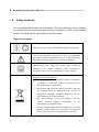
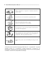
----------------------------------------------------------------- Smart Blocker Operator’s Manual Operator’s Manual Smart Blocker HBK-7000 1 2 Smart Blocker Operator’s Manual ----------------------------------------------------------------- IMPORTANT NOTICE The information in this publication has been carefully checked and is believed to be entirely accurate at the time of publication. HUVITZ assumes no responsibility, however, for possible errors or omissions, or for any consequences resulting from the use of the information contained herein. HUVITZ reserves the right to make changes in its products or product specifications at any time and without prior notice, and is not required to update this documentation to reflect such changes. © 2002 - 2004 HUVITZ Co., Ltd. 689-3, Geumjeong-dong, Gunpo-si, Gyeonggi-do, 435-862, Republic of Korea All rights are reserved. Under copyright laws, this manual may not be copied, in whole or in part, without the prior written consent of HUVITZ Co., Ltd. ----------------------------------------------------------------- Smart Blocker Operator’s Manual 3 CONTENTS 1. Safety Information ...............................................................................................5 1.1. Introduction ........................................................................................................5 1.2. Safety Symbols ..................................................................................................6 1.3. Environment Factors ..........................................................................................7 1.4. Safety Precaution ..............................................................................................9 2. Features .............................................................................................................12 3. Notes for Using the Instrument.........................................................................14 4. Configurations ...................................................................................................15 4.1. Main Body – front view.....................................................................................15 4.2. Main Body – rear view .....................................................................................16 4.3. Displays ...........................................................................................................18 5. Installation..........................................................................................................21 5.1. Installation Procedure ......................................................................................21 5.1.1. Interfacing with Frame Reader .................................................................22 5.1.2. Interfacing with Lens Edger ......................................................................23 5.2. 6. System Configuration.......................................................................................24 Using the Instrument .........................................................................................25 6.1. Starting a Job...................................................................................................25 6.1.1. Starting a job with a frame data from Frame Reader ................................25 6.1.2. Starting a job with a memory data ............................................................26 4 Smart Blocker Operator’s Manual ----------------------------------------------------------------- 6.2. Designing Layout .............................................................................................28 6.2.1. Selecting layout options ...........................................................................28 6.2.2. Inputting layout data.................................................................................29 6.2.3. Shape and drilling layout design ..............................................................30 6.3. Setting Edging Options ....................................................................................31 6.4. Other functions ................................................................................................33 7. Troubleshooting.................................................................................................34 7.1. The Smart Blocker does not start .....................................................................34 7.2. The Lens Holder is stuck in its standby position and doesn’t move to the center of the lens stage...........................................................................................................34 7.3. The Smart Blocker doesn’t receive any data from the Frame Reader ...............34 7.4. The Lens Edger doesn’t receive any data from the Smart Blocker ...................35 8. Components List ...............................................................................................36 8.1. Standard Components .....................................................................................36 8.2. Optional Components ......................................................................................36 9. Service Information ...........................................................................................37 Appendix A. Specifications ...............................................................................39 ----------------------------------------------------------------- Smart Blocker Operator’s Manual 1. 5 Safety Information 1.1. Introduction Safety is everyone’s responsibility. The safe use of this equipment is largely dependent upon the installer, user, operator, and maintainer. It is imperative that personnel study and become familiar with this entire manual before attempting to install, use, clean, service or adjust this equipment and any associated accessories. It is paramount that the instructions contained in this manual are fully under stood and followed to enhance safety to the patient and the user/operator. It is for this reason that the following safety notices have been placed appropriately within the text of this manual to highlight safety related information or information requiring special emphasis. All user, operators, and maintainers must be familiar with and pay particular attention to all warning and cautions incorporated herein. ! WARNING “Warning” indicates the presence of a hazard that could result in severe personal injury, death or substantial property damage if ignored. NOTE “Note” describes information for the installation, operation, or maintenance of which is important but hazard related if ignored. ! CAUTION “Caution” indicates the presence of a hazard that could result in minor injury, or property damaged if ignored. 6 Smart Blocker Operator’s Manual ----------------------------------------------------------------- 1.2. Safety Symbols The International Electro technical Commission (IEC) has established a set of symbols for medical electronic equipment, which classify a connection or warn of any potential hazard. The classifications and symbol s are shown below. Save this instruction I and O on power switch represent ON and OFF respectively. This symbol identifies a safety note. Ensure you understand the function of this control before using it. Control function is described in the appropriate User’s or Service Manual. Identifies the point where the system safety ground is fastened to the chassis. Protective earth connected to conductive parts of Class I equipment for safety purposes. Disposal of your old appliance 1. When this crossed-out wheeled bin symbol is attached to a product, it means the product is covered by the European Directive 2002/96/EC. 2. All electrical and electronic products should be disposed of separately from the municipal waste stream via designated collection facilities appointed by the government or the local authorities. 3. The correct disposal of your old appliance will help prevent potential negative consequences for the environment and human health. 4. For more detailed information about disposal of your old appliance, please contact your city office, waste disposal service or the shop where you purchased the product. ----------------------------------------------------------------- Smart Blocker Operator’s Manual 1.3. Environment Factors Avoid the following environments for operation or storage: Where the equipment is exposed to water vapor. Don’t operate equipment with a wet hand. Where the equipment is exposed to direct sunlight. Where the temperature changes extremely. Normal operating temperature range is from 10℃ to 35℃, Humidity is from 30% to 75%. Where it is near the heat equipment. Where the humidity is extremely high or there is a ventilation problem. Where the equipment is subject to excessive shocks or vibrations. 7 8 Smart Blocker Operator’s Manual ----------------------------------------------------------------- Where equipment is exposed to chemical material or explosive gas. Be careful not to be inserted dust, especially, metal. Don’t disassemble the product or open. We aren’t responsible for it for nothing. Be careful not to close the fan located on the lateral or rear side of the equipment. Don’t plug the AC power cord into the outlet before the connection between instruments of the e q u i p m e n t i s c o m p l e t e d . This can generate the defect. Pull out the power cord with holding the plug, not the cord. Avoid places where the ambient temperature falls below 10℃ or exceeds 40℃ for normal operation, or below –10℃ or exceeds 55℃ storage, or below -40℃ or exceeds 70℃ for transportation. Humidity should be maintained between 30 and 75% for normal operation, or between 10 and 95% for transportation and storage. ----------------------------------------------------------------- Smart Blocker Operator’s Manual 1.4. 9 Safety Precaution This equipment has been developed and tested according to safety standards as well as national and international standards. This guarantees a very high degree of safety for this instrument. The legislator expects us inform the user expressively about the safety aspects in dealing with the instrument. The correct handling of this equipment is imperative for its safe operation. Therefore, please read carefully all instructions before switching on this instrument. For more detailed information, please contact our Customer Service Department or one of our authorized representatives. 1. This equipment must not be used (a) in an area that is in danger of explosions and (b) in the presence of flammable, explosive, or volatile solvent such as alcohol, benzene or similar chemicals. 2. Do not put or use this instrument in humid rooms. Humidity should be maintained between 30 and 75% for normal operation. Do not expose the instrument to water splashes, dripping water, or sprayed water. Do not place containers containing fluids, liquids, or gases on top of any electrical equipment or instruments. 3. The equipment must be operated only by, or under direct supervision of a properly trained and qualified person. 4. Installation and modifications of this equipment may only be carried out by Huvitz’s service technicians or other authorized persons by Huvitz. 5. Customer maintenance of this equipment may only be performed as stated in the Operator’s Manual. Any additional maintenance may only be performed by Huvitz’s service technicians or other authorized persons. 6. The manufacturer is only responsible for effects on safety, reliability, and performance of this equipment when the following requirements are fulfilled: (1) The electrical installation in the respective room corresponds to the specifications stated in this manual and (2) This equipment is used, operated, and maintained according to this manual. 10 Smart Blocker Operator’s Manual ----------------------------------------------------------------- 7. The manufacturer is not liable for damage caused by unauthorized tampering with the instrument(s). Such tampering will forfeit any right to claim under warranty. 8. This equipment may only be used together with accessories supplied by Huvitz. If the customer makes use of other accessories, use them only if their safe usability under technical aspect has been proved and confirmed by Huvitz or the manufacturer of the accessory. 9. Only the person who has undergone proper training and instructions is authorized to install, use, operate, and maintain this equipment. 10. Keep the Operator’s Manual in a place easily accessible at all times for persons operating and maintaining the equipment. 11. Do not force cable connections. If a cable does not connect easily, be sure that the connector (plug) is appropriate for the receptacle (socket). If you cause any damage to a cable connector(s) or receptacle(s), let the damage(s) be repaired by an authorized service technician. 12. Please do not pull on any cable. Always hold on to the plug when disconnecting cables. 13. Before every operation, visually check the equipment for exterior mechanical damage(s) and for proper function. 14. Do not cover any ventilation grids or slits. 15. Immediately turn off and unplug any equipment that gives off smoke, sparks, strange noises, or odors. 16. Be sure to disconnect power cord before connecting or disconnecting the cables. Otherwise, the cable may be damaged, which may result in fire or electric shock. 17. This equipment generates, uses and can radiate radio frequency energy and, if ----------------------------------------------------------------- Smart Blocker Operator’s Manual 11 not installed and used in accordance with the instructions, may cause harmful interference to other instruments in the vicinity. However, there is no guarantee that interference will not occur in a particular installation. If this equipment does cause harmful interference to other instruments, which can be determined by turning the equipment off and on, the user is encouraged to try to correct the interference by one or more of the following measures: Reorient or relocate the receiving instrument Increase the separation between the equipment Connect the equipment into an outlet on a circuit different from that to which the other instrument(s) are connected Consult the manufacturer or field service technician for help 18. "External equipment intended for connection to signal input, signal output or other connectors, shall comply with relevant IEC standard (e.g., IEC 60950 for IT equipment and IEC 60601 series for medical electrical equipment). In addition, all such combinations - systems - shall comply with the standard IEC 60601-1-1, Safety requirements for medical electrical systems. Any person who connects external equipment to signal input, signal output or other connectors has formed at system and is therefore responsible for the system to comply with the requirements of IEC60601-1-1. If, in doubt, contact qualified technician or your local representative." (Or some cases, for example LCD Monitor, "This instrument is intended to connect to the medical instrument only, which complies with standards of IEC 60601 series.") 19. Do NOT touch signal input/signal output and patient simultaneously. 12 Smart Blocker Operator’s Manual ----------------------------------------------------------------- 2. Features 1. The Huvitz Smart Blocker HBK-7000 is a blocking instrument used to attach a lens cup on a lens to edge in the lens edger such as CPE-4000 and HPE-7000. In the meantime it provides interfaces for data communication to receive frame shape data from the Frame Reader and to transmit edging job data to the Lens Edger for edging. The communication interface allows two lens edging instrument connected at the same time. 2. It guides the operator designing a layout and setting edging conditions for an edging job with well arranged menu icons and guidance displayed on the wide 8.4 inch color LCD along with handy touch interface. 3. During the operator designs a layout job, it is possible to redesign the frame shape especially for half-rims and rimless frame with the Digital Pattern function. If it is interfaced with the Huvitz HPE-7000 lens edger, it also supports designing holes and notches for a drilling job additionally. 4. On the display it shows the live images of working lens on the lens stage with guide marks to allow the operator position the lens on the correct blocking position with ease. 5. The lens put on the lens stage is automatically leveled by the lens leveler and the lens holder. It guarantees the operators blocking job with precision for lenses with all that different shapes at any position on the lens when they attach the lens block by pushing the blocking arm. 6. It also supports the operator saving edging jobs on the external SD memory card for future reuse. Saved job data can be reloaded for another edging job by using the menu function in it where barcode reader is allowed to input job number to pick up a job. ----------------------------------------------------------------- Smart Blocker Operator’s Manual 7. 13 In addition to blocking function, the operator can easily adjust the viewing angle of the display by pushing and pulling the display panel. 14 Smart Blocker Operator’s Manual ----------------------------------------------------------------- 3. Notes for Using the Instrument 1. Do not hit or drop the hardware instrument. The hardware instrument may be damaged if it receives a strong impact. The impact can damage the function of the instrument. So handle it with care. 2. Install the hardware instrument on a level, stabilized table with no vibration to keep it normal state. 3. Don't use organic solution such as thinner, benzene, etc. to clean the surface of the hardware instrument. It may damage the instrument. 4. Use only with correct type of power adaptor for the hardware instrument, or the hardware instrument may get damaged or not work properly. 5. Disconnect the power supply and consult the dealer in case of smoke, strange odors, or noise during operation. 6. This product may malfunction due to electromagnetic waves caused by portable personal telephones, transceivers, radio-controlled toys, etc. Be sure to avoid having the above objects, which affect the normal operation of the product, brought near the product. ----------------------------------------------------------------- Smart Blocker Operator’s Manual 4. 15 Configurations Main Body – front view 4.1. ① Display Panel ③ ② Lens Holder ⑤ Block Holder ④ ① Blocking Arm Lens Leveler Display Panel Color LCD panel along with touch interface. Displays live images of the working stage and various menu icons and input fields for designing en edging job. And tilts between 45 to 65 degree for the viewing angle of the operator. ② Lens Holder 16 Smart Blocker Operator’s Manual ----------------------------------------------------------------- Holds the lens on the lens leveler for blocking. ③ Blocking Arm Provides the block holder and the handle for blocking. ④ Lens Leveler Balances the lens level with three level foots. ⑤ Block Holder Holds the lens block to be attached on the lens. Main Body – rear view 4.2. ① ③ SD Card Socket ④ Power Inlet Power Switch ⑤ Fuse Holder ② Communication Ports ----------------------------------------------------------------- Smart Blocker Operator’s Manual ① SD Card Socket Inserts SD card memory. ② Communication Ports Provides connection ports for other instruments or devices. Edger1 port for the first lens edger Edger2 port for the second lens edger Tracer port for a Frame Reader Barcode port for a barcode reader Console port for future use ③ Power Switch Turns on and off the power to the instrument. ④ Power Inlet Connects the power cord. ⑤ Fuse Hold Contains fuses. 17 18 Smart Blocker Operator’s Manual ----------------------------------------------------------------- 4.3. Displays Below screen shows the main display for designing an edging job. Menu Bar Job Number R-side Selection L-side Selection Preview R/L Sync. Layout Menu Touch Lock Live Image Area Edging Option Men u Transmission Button Menu Bar The menu bar provides system menu functions. Job menu is for creati ng, saving or loading a job data. Option menu is for setting system-pr oviding options or executing optional functions. Display menu is for ex ----------------------------------------------------------------- Smart Blocker Operator’s Manual 19 ecuting display control functions. Help menu provides the system infor mation. Job Number The job number field shows the job number of current job data. Touching the field area executes the dialog window for inputting a new job number for a newly created job. R-side Selection This button selects right side. It refreshes the layout menu, edging opti on menu, and frame shape data on the live image area with the infor mation in current job of right side. L-side Selection This button selects left side. It refreshes the layout menu, edging optio n menu, and frame shape data on the live image area with the inform ation in current job of left side. R/L Sync. This button turns on and off the R/L synchronization option to synchronize the layout data and edging options of right side with the left side. Preview This area shows the frame material information gotten from the Frame Reader and summarized layout information on the thumbnail image of the frame shape of current job. Layout Menu The layout menu aids the operator design a layout for an edging job with input fields and layout options. The operator would input the FPD, optical height, PD information and may choose blocking type, lens type as options. 20 Smart Blocker Operator’s Manual ----------------------------------------------------------------- Also the digital pattern and the hole & notch design functions are supported. The digital pattern function allows the operator to modify or change the frame shape. The hole & notch design function allows the operator to add drilling job information if the Smart Blocker is connected to the Huvitz HPE7000 lens edger. Live Image Area This area shows the live images of the lens stage where target lens is put for a blocking job. On the live images, guide drawing is displayed to help the operator position the target lens on the blocking position more easily. Touch Lock This small button locks and unlocks the touch screen. Edging Option Menu The edging option menu aids the operator set edging conditions such as lens material, edging type, edging position, polishing, safety bevel, safety mode for current job. Transmission Button This button transmit current job to connected edger(s). ----------------------------------------------------------------- Smart Blocker Operator’s Manual 5. 21 Installation Before proceeding to install a HBK-7000 blocker with a lens-edging system, check the package components listed in chapter 8 of this manual. It is strongly required to pay attention to every instruction or information on the package and handle with care for every part when opening and pulling out the contents in the package. After all the package contents are checked correct, prepare the main body for installation by carefully removing protective materials attached on the instrument. NOTE Do not remove protective materials by force. It may damage the internal alignment of the instrument. 5.1. Installation Procedure Step 1, Place the main body on the work bench or on any stable table. For the complete installation, the Frame Reader and the Lens Edger to be interfaced with are required to be installed within the reach of its interface cable. Step 2, Turn off the power switch of the main body if it’s on the position “ON(1). Connect the power cord to the power inlet in the main body. Step 3, Connect the power cord to the wall outlet. Step 4, Turn on the power and wait until the initial screen disappears and the main screen is shown on the LCD screen. Step 5, Adjust the viewing angle of the LCD to appropriate working height. Then check if the touch screen is responding correctly by touching menu icons or else. If it’s not 22 Smart Blocker Operator’s Manual ----------------------------------------------------------------- responding at all, check if the “Touch Lock” button is enabled. In that case touch the button once to unlock the touch screen. Edger-2 5.1.1. Edger-1 Barcode Tracer Console Interfacing with Frame Reader Step 1, Turn the power of instruments off, both the Frame Reader and the Smart Blocker. Step 2, Connect a 9-pin serial interface cable to the TRACER port of the Smart Blocker. Step 3, Connect the other side of the serial interface cable to either the EDGER-1 port or the EDGER-2 port of the Frame Reader. Step 4, Turn on the power of the Frame Reader and wait unit it finishes its initialization sequence. Step 5, Set the EDGER-1 option of the Frame Reader to “Edger” and save the chage. Refer to the Operator’s Manual of the Frame Reader for the details about how to configure the instrument. ----------------------------------------------------------------- Smart Blocker Operator’s Manual 23 Step 6, Turn the power of the Smart Blocker on and wait until it displays the main screen. Step 7, Put a frame on the grippers of the Frame Reader and press the button “BOTH” for reading it. Wait until it finishes reading the frame and transmits the data to the Smart Blocker. Step 8, Check whether the frame data is received correctly by the Smart Blocker correctly. 5.1.2. Interfacing with Lens Edger Step 1, Turn the power of instruments off, both the Lens Edger and the Smart Blocker. Step 2, Connect a 9-pin serial interface cable to either the EDGER-1 port or the EDGER-2 port of the of the Smart Blocker. Step 3, Connect the other side of the serial interface cable to the TRACER port or to the BLOCKER port of the edger(if the edger supports drilling function, connect the cable to the BLOCKER port. Otherwise connect it to the TRACER port). Step 4, Turn on the power of the Lens Edger and wait unit it finishes its initialization sequence. Step 5, Turn the power of the Smart Blocker on and wait until it displays the main screen. Step 6, Load a job data from the internal memory of the Smart Blocker and transmit it to the Lens Edger (touch the “Transmission” button on the LCD). Step 7, Check whether the job data is received correctly by the Lens Edger correctly. 24 Smart Blocker Operator’s Manual ----------------------------------------------------------------- 5.2. System Configuration Currently there are two different types of configuration is supported. One is to interface the Smart Blocker with single Frame Reader and single Lens Edger like the figures below. The other type is to interface is with one Frame Reader and two sets of Lens Edger. NOTE Any model of Huvitz lens edger is allowed to be interfaced with other than CPE3000. And any model of Huvitz Frame Reader is allowed to be interfaced with other than CFR-3000. ----------------------------------------------------------------- Smart Blocker Operator’s Manual 6. 25 Using the Instrument 6.1. Starting a Job There are two ways of starting a job for blocking. One is to start with a frame shape data newly received from the Frame Reader. The other is to start with a job data in the memory, either in the internal memory or in the external SD memory. 6.1.1. Starting a job with a frame data from Frame Reader When the Frame Reader finishes reading a frame or a pattern, it transmits the read data to other instrument(s) automatically. And the data is loaded and set in the Smart Blocker automatically. Then a new job for blocking is also started by itself. 26 Smart Blocker Operator’s Manual ----------------------------------------------------------------- 6.1.2. Starting a job with a memory data The Smart Blocker not only provides preset frame shape data in its internal memory but also supports saving and loading job data from the external memory interface. The Job menu in the menu bar provides all the job related functions such as saving a job, loading a job and etc. Executing the job menu Touch the “Job >> Load…” menu in the menu bar. Then the “Job Manager” dialog is executed. Browsing and selecting a job data In the “Job Manager” dialog, job data are classified in three categories, recently received data from the Frame Reader, preset data in the internal memory, previously saved data in the external memory. Select one of the categories then job numbers are listed on the right side. The operator may select a job directly by touching a job number or by searching one with the aid of the barcode reader connected to the Smart ----------------------------------------------------------------- Smart Blocker Operator’s Manual 27 Blocker if available. Loading a job data Touch the button on the bottom of the “Job Manager” dialog, it loads selected job data and opens it. 28 Smart Blocker Operator’s Manual ----------------------------------------------------------------- 6.2. Designing Layout Layout design can be viewed as three different works, selecting layout options, inputting layout data, shape and drilling layout design. 6.2.1. Selecting layout options Frame PD inputs frame PD value. It’s automatically input when a frame is traced on both sides by the Frame Reader. inputs bridge size value manually. It is required to input the bridge size when a pattern or only one side of a frame is traced by the Frame Reader. Optical Height (OH) inputs OH value by measuring the OH point from the boxing center of the rim. inputs OH value by measuring the OH point from the bottom of the rim. inputs OH value by measuring the OH point from the lower side of the rim where the PD position of measuring side is vertically aligned with the OH point. ----------------------------------------------------------------- Smart Blocker Operator’s Manual 29 PD inputs monocular PD value. inputs binocular PD value. Blocking Mode selects the boxing center mode. selects the optical center mode. Lens Type selects the type for a single vision lens marked by a lensmeter. Other types of lens are also can be blocked by this type if the operator is to block a lens by marking on the blocking position with a lensmeter. selects the type for a bi-focal lens with its near segment semicircular shape. selects the type for a bi-focal lens with its near segment circular shape. selects the type for a progressive lens with specific marks printed on it. 6.2.2. Inputting layout data To input a value for layout, touch the input field for the value item. Then it executes the keypad dialog. Number input can be made either by touch the number buttons directly or by turning the dial on the right downer side of the dialog by touching and dragging down repeatedly. “C” button is for clearing the existing input. Backward arrow button is for backspace. “+/-“ button is for converting the sign of input value. 30 Smart Blocker Operator’s Manual ----------------------------------------------------------------- 6.2.3. Shape and drilling layout design The Smart Blocker allows the operator changes the frame shape to edge by using the Digital Pattern function in case the operator is determined that frame-fitting is not affected by it. In case the Smart Blocker is interfaced with a lens edger that supports drilling function, the operator can design and add layout info for drilling by using the “Hole & Notch Design” function. Otherwise the function does not work. executes the Digital Pattern function. executes the Hole & Notch Design function. ----------------------------------------------------------------- Smart Blocker Operator’s Manual 6.3. 31 Setting Edging Options Edging options are provided to allow the operator sets edging condition for each job. Edging conditions selected in the Smart Blocker are transmitted to the lens edger with other job information and set automatically on the edger’s LCD screen when it’s loaded. Those options are also able to be re-edited on the edger’s LCD screen before starting edging. Lens Material selects a plastic lens for edging. selects a poly-carbonate lens for edging. selects a high index lens for edging. selects a glass or mineral lens for edging. selects a trivex lens for edging. Edging Type selects beveled edging for a rimmed frame. selects grooved edging for a half-rim frame. selects flat edging for a rimless frame. Edging Position (for beveling or grooving) selects input method as offset from the front side. selects input method as offset from the rear side. selects input method as base curve of the lens. selects input method as percent from the front side. 32 Smart Blocker Operator’s Manual ----------------------------------------------------------------- Polishing selects polishing option on. selects polishing option off. Safety Bevel – Front selects no safety bevel. selects normal safety bevel. Safety Bevel – Rear selects no safety bevel. selects normal safety bevel. selects larger safety bevel than normal. Safety Mode selects the safety mode option of edger off. selects the safety mode option of edger on. For more detailed information about edging options, refer to the Operator’s Manual of the Lens Edger. ----------------------------------------------------------------- Smart Blocker Operator’s Manual 6.4. 33 Other functions There are some other functions that are not used for designing layout and setting edging options. R/L Selection selects right side for designing and blocking. selects left side for designing blocking. R/L Synchronization selects the R/L Synchronization option on. This enables the Smart Blocker synchronize the value of right side and left side when the operator inputs layout data and sets edging options for one side. selects the R/L Synchronization option off. Touch Lock unlocks the touch screen. locks the touch screen. Transmission triggers transmitting current job data through outgoing port(s). 34 Smart Blocker Operator’s Manual ----------------------------------------------------------------- 7. Troubleshooting 7.1. The Smart Blocker does not start Check if the power cord is connected correctly. Pull out the fuse holder and check if any of the fuses is burned. If any of them is burned, replace it with the same type. The Lens Holder is stuck in its standby position and doesn’t 7.2. move to the center of the lens stage To move the lens holder to and from the lens stage, lift up to the top and then turn it. The Smart Blocker doesn’t receive any data from the Frame 7.3. Reader Check if the serial interface cable is connected and fixed firmly. Check if the port of the Smart Blocker where the Frame Reader is connected is “Tracer”. Check if the port of the Frame Reader where the Smart Blocker is connected is either “Edger-1” or “Edger-2”. Otherwise turn off the instruments and change the port connection appropriately. Check if the port setting in the options menu of the Frame Reader is correct. If the problem continues in spite of all the measures above, replace the serial ----------------------------------------------------------------- Smart Blocker Operator’s Manual 35 interface cable with the same type provided by Huvitz. The Lens Edger doesn’t receive any data from the Smart 7.4. Blocker Check if the serial interface cable is connected and fixed firmly. Check if the port of the Lens Edger where the Smart Blocker is connected is either “Tracer” or “Blocker”. Otherwise turn off the instruments and change the port connection appropriately. Check if the port of the Frame Reader where the Lens Edger is connected is either “Edger-1” or “Edger-2”. Otherwise turn off the instruments and change the port connection appropriately. Check if the port setting in the options menu of the Lens Edger is correct. If the problem continues in spite of all the measures above, replace the serial interface cable with the same type provided by Huvitz. 36 Smart Blocker Operator’s Manual ----------------------------------------------------------------- 8. 8.1. 8.2. Components List Standard Components Main Body 1 EA Touch Pen 1 EA SD Memory Card 1 EA Extra Lens Support (for frame change) 1 EA Power Cord 1 EA Interface Cable (9-pin DSub Serial, 2m) 1 EA Spare Fuse (250Vac T3.15AL) 2 EA Operator’s Manual 1 EA Optional Components Barcode Reader 1 EA ----------------------------------------------------------------- Smart Blocker Operator’s Manual 9. 37 Service Information If the instrument appears malfunctioning, before calling a customer service, it is highly recommended to check the instrument according to the troubleshooting procedure in section 16 of this manual. If any problem persists or the instrument is damaged or malfunctioning, contact Huvtiz or local distributor for service with the following information: Name of the product: HBK-7000 Serial number of the product: refer to the 9-digit number on its product label or name plate Descriptions of Problem: In detail Date of Purchase: Dealer’s Name: Dealer Address: Dealer Phone No.: Version No.: Serial No.: ( Huvitz recommends customers to fill up the above form after purchase and retain this manual as a permanent record of purchase.) 38 Smart Blocker Operator’s Manual ----------------------------------------------------------------- Write us at: Tel: +82-31-442-8868 HUVITZ Co., Ltd. Fax: +82-31-442-8619 Huvitz B/D, 689-3 Geumjeong-dong http://www.huvitz.com Gunpo-si Gyeonggi-do, 435-862, e-mail: [email protected] Republic of Korea ----------------------------------------------------------------- Smart Blocker Operator’s Manual Appendix A. Specifications Layout Ranges Lens Size Max. 80 mm Frame PD 30 ~ 99.5 mm PD 30 ~ 99.5 mm (Monocular PD : 15 ~ 49.75 mm) Optical Height ±15 mm Layout Options FPD Frame PD Bridge size Delta Y Optical Height Box height Mix height Single vision lens Lens Type Bi-focal lens (semicircle, circle) Progressive lens Vertical Horizontal Shape Change Free directional Enlarge Hole design Drilling Layout Support Notch design 39 40 Smart Blocker Operator’s Manual ----------------------------------------------------------------- Edging Options Lens Material Edging Type Bevel Grooving Flat Polishing Supported Safety Bevel Front (Single level) Rear (2 levels) Position Adjustment By offset (Front, Rear) By percent (Front) By base curve Plastic Poly-carbonate High Index Glass (Mineral) Trivex Blocking Method Manual Mode Minimum 8 MB Position Accuracy Diameter 0.5 mm Axis Accuracy ±0.5° Lens-Leveling Supported Display LCD 8.4 inch TFT color Touch Screen Supported Viewing Angle Adjustment 45 ~ 65° Interfaces ----------------------------------------------------------------- Smart Blocker Operator’s Manual Frame Reader 1 channel Lens Edger 2 channels Barcode Reader 1 channels Power Input AC 100-240V~ Frequency 50 / 60 Hz Consumption 35 W Dimensions & Weight Dimension 220(W) * 250(D) * 377(H) Weight 7.5 Kg 41 42 Smart Blocker Operator’s Manual -----------------------------------------------------------------