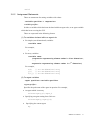
1
artisoc
English Edition
User Manual
Disclaimer
(1)
The copying or reproduction of all or part of this manual, using any method, including but
not limited to electronic copying, mechanical copying, photographic copying, and audio
recording, for any purpose whatsoever without our expressed written permission is strictly
prohibited.
(2)
The contents of this manual are subject to change without notice.
(3)
Every effort has been made to ensure that the contents of this manual are accurate, but in
the event that any items are discovered which are or might be erroneous, please contact us.
(4)
Section (3) notwithstanding, we accept no responsibility for the consequences of putting
this information into actual use.
(5)
We will replace any manual which is incorrectly paginated or which has missing pages.
© 2006 KOZO KEIKAKU ENGINEERING Inc. All rights reserved.
“Kozo Keikaku Engineering” and its logo are registered trademarks of Kozo Keikaku
Engineering Inc.
Kozo Keikaku Engineering Inc.
4-38-13 Honmachi, Nakano-ku, Tokyo, 164-0012 Japan
Tel: +81-3-5342-1125
Innovative Information Technology Dept., artisoc Section
Chapter 1
Introduction to the artisoc
artisoc User Manual
1
1.1 Running a Sample Model
We have included sample simulation models in order to give you a feel for how the
artisoc actually works. When you use model files (*.model), you will quickly be able to
run the simulation after just a minimum amount of set-up.
Now let’s get accustomed to using artisoc by actually trying it out.
Preparation
1.
Click [Programs] – [artisoc] – [models] – [Words of mouth Model] from “start”
menu.
1.1.1 Word-of-Mouth Model
— A simulation of information which is spread by word of mouth
(1) About this model
This model simulates the process that a rumor spreads by having a small number of
people holding information pass this information by word of mouth. A Walker agent who
has the information (red) is wandering around in a “two-dimensional space”. When this
agent bumps into an agent who does not have the information (green), the information is
conveyed, and the color of the agent which was bumped into changes from green to red.
The number of red agents gradually increases, and the rumor spreads.
Of course, you are free to modify the various settings in this model, but first let’s try
running a simulation as is.
(2) Running a simulation
When you open the “mouth_com_e.model” file, the window such as that shown below
will open.
2
artisoc User Manual
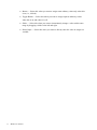
Tree:
Tree window is the most basic screen in the artisoc, which displays the various
components in a tree structure,. In the tree, there will always be one Universe. Under this,
components such as spaces, agents, and variables can be defined. These will be
explained in detail in Chapter 2.
Now let’s try actually running this model. To run it, use the Run Panel, which is under
the menu bar. You can float the Run Panel using drag-and-drop.
Start button: Starts the simulation
Single Step button: Runs just one step of the simulation
Pause button: Pauses the simulation
Stop button: Stops the simulation
Let’s run a simulation. Click the Start button. Was a screen such as the following
displayed?
artisoc User Manual
3
(3) Simulation results
Three windows — Tree, Time Series Graph (Headcount), and Space — like those shown
above were displayed, right? In these windows, the simulation will continue, and the
results will be displayed in real time, until Stop or Pause is pressed, or until the
information has been passed to all of Walker agents.
1.2 Arranging the Simulation
In the previous section we tried actually running a model, and got one result. Now let’s
try to elicit different results by changing the settings.
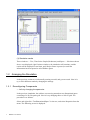
1.2.1 Reconfiguring Components
— Let’s try changing the space size
In the previous simulation, the walkers were moving around on two-dimensional space
consisting of a 50×50 square grid. Now let’s try changing this to a 100×25 grid. The
procedure is as follows.
Select and right-click “TwoDimensionalSpace” in the tree, and select Properties from the
menu. The following screen is displayed.
4
artisoc User Manual
Change the Space Size X field from 50 to 100 and the Space Size Y field from 50 to 25.
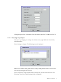
1.2.2 Reconfiguring Output
Next, let’s try changing two settings for the time series graph. Make the lines thicker,
and add markers.
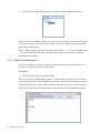
Select Settings > Outputs. The following screen is displayed.
Make the red walker count graph easier to read by adding markers to the vertices of the
lines and by making the lines thicker.
Select Time Series Graph of Red Walkers from the list, and click the Edit button. The
following Time Series Graph Settings dialog is displayed.
artisoc User Manual
5
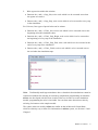
Select “WalkersWithInfo” from Time Series Graph Element List, and click the Edit
button.
Change Line Width from 2 pt to 4 pt, check Show Markers, and click the OK button.
We’re ready once again. Click the Start button in the Run Panel.
6
artisoc User Manual
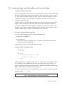
1.3 Creating a Simple Model
In this section, you will learn the basic elements and procedures for building multi-agent
models completely from scratch. Creation process is as follows.
Component Placement and Settings
▼
Outputs Settings
▼
Agent Rule Declarations
▼
Run and Debug
This flow chart will appear many times during the creation process. It is good to have a
general understanding of what work you are doing at any given time.
In this section, we will also learn conditional branching (If statements), initial value
assignment methods, and debugging, in terms of important programming concepts.
Although they are still in the early stages as a rule, if you are a beginner you should try
to familiarize yourself with the programming’s distinctive expression and writing
methods. If you are somewhat experienced, you can probably get away with scanning
over this section quickly.
Now let’s create a model in which a number of turtles move about — Moving Turtle
Model.
artisoc User Manual
7
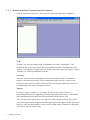
1.3.1 About the artisoc Programming Environment
Start up artisoc and select File > New. A screen such as the following is displayed.
Tree:
In artisoc, the various elements used in simulations are called “components”. The
component tree in the Tree window shows hierarchical structure of components in the
form of a tree diagram. A single Universe always exists at the top of tree. Spaces, Agents,
Variables, etc. will be placed under Universe.
Universe:
Only one Universe exists at the highest level of the simulation model. A simulation
model is constructed by placing various components under Universe. A space is not
necessarily required as it would be in the real universe; abstract models which have no
accompanying space can be constructed as well.
Spaces:
In a space, agents, variables, etc. are placed. In the current version of artisoc, a
three-dimensional space is supported. Normally, Grid models providing a vertical and a
horizontal dimension are used, but a Hexagon model can be used as well.
You can connect the end of space to the opposite end by specifying Loop. If you select
Loop, then agents which disappear off of the right border will reappear on the left border.
However, since this functionality is only in effect within artisoc’s functions, in programs
you have to write the code to loop.
8
artisoc User Manual
Agents:
In simulations, components which move and behave according to specific rules are
called “agents”. Agents affect other components and are affected by other components.
With artisoc, using simple procedures, you can arrange these sorts of agents and perform
simulations involving them.
Variables:
You can store the information and state (number, character, etc.) associated with each
component, in its variables. You can think of these as being roughly synonymous with
the x and y variables in mathematics.
A distinctive characteristic of variables which are handled in computers is that they
always have a type (Integer, Double, String, etc.), and what type a variable is going to be
must be declared prior to using it. You must always use variables which are appropriate
for the type of information stored in them.
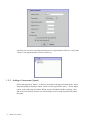
1.3.2 Adding a Component (Space)
Component Placement and Settings
▼
Outputs Settings
▼
Agent Rule Declarations
▼
Run and Debug
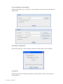
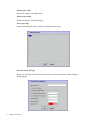
When you right-click Universe in the component tree, a menu will appear. Select Add
Space. Space Properties dialog will appear. Input “Space1” for the Space Name, select
Grid Model for the Space Type, input “50” for the Space Size X and Y, input “1” for the
Layer, and select Don’t Loop for the End of Space, as the following screenshot. When
you have finished, click OK to close the dialog.
artisoc User Manual
9
You have now created a two-dimensional space for a grid model in Universe. Verify that
“Space1” has appeared under Universe in the tree.
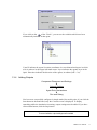
1.3.3 Adding a Component (Agent)
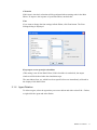
Select and right-click “Space1” in the tree, and select Add Agent from the menu. Agent
Properties dialog is displayed. Input “Turtle” for the Agent Name and “1” for the Agent
Count, as the following screenshot. When you have finished with these settings, click
OK to close the dialog. We have now successfully created a turtle agent directly under
the space.
10
artisoc User Manual
If you click on the
of the “Turtle”, you can see the variables which have been
automatically included in that agent.
X and Y indicate the agents’ location coordinates in a two-dimensional space in which
(0,0) is taken to be the upper left-hand corner. Layer indicates the agents’ layer in the
space. Direction indicates the direction of the agents, in radians (360º = 2π).
1.3.4 Adding Outputs
Component Placement and Settings
▼
Outputs Settings
▼
Agent Rule Declarations
▼
Run and Debug
You have now successfully configured a simple model, but at this point, if you click the
Start button in the Run Panel, only the Console screen is displayed. To display
something while the simulation is running, output settings must be added. If you have
clicked Start button, click the Stop button.
To run a simulation, output settings must be added.
artisoc User Manual
11
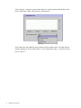
Select Settings > Outputs to open Output Item List. Output options include Map, Time
Series Graph, Bar Graph, Values Screen, and Data File.
Select Map from the pulldown menu, and then click the Add button. The Map Settings
dialog is displayed. Set the Map Name to “Two-dimensional_map_1”, and set the map
title to “Space1”.
12
artisoc User Manual
Click Add in the Map Element List area. The Element Settings dialog is displayed. Input
“Turtle” for the Element Name, and click OK to close the dialog. You have now added
Turtle to the Map Element List.
artisoc User Manual
13
Click OK on the Map Settings dialog to close it. The Two-dimensional_map_1 is added
to the Output Item List. Click OK to close the dialog.
1.3.5 Running a Simulation (Do-Nothing Turtle)
Let’s try clicking on the Start button in the Run Panel. In this state, the agent does not
have any rules yet, so it cannot move from the location at which it was placed. But you
have at least built the minimal model for an agent to move around.
14
artisoc User Manual
Click the Stop button to stop the simulation. Select File > Save As, and save the model
as “prog01.model”.
1.3.6
Opening the Rule Editor
Component Placement and Settings
▼
Outputs Settings
▼
Agent Rule Declarations
▼
Run and Debug
The agent cannot move as it is, so let’s give the agent a rule. We’ll add the new
information to prog01.model.
Select and right-click the Turtle in the component tree. Select Rule Editor from the menu.
The Rule Editor window for the agent is displayed.
Agt_Init{} and Agt_Step{} are already written. Agt_Init{} is an initial rule which is only
artisoc User Manual
15
executed once, when the agent is first created in the simulation. Agt_Step{} is an
execution rule which is executed at every step while running the simulation. Curly
braces { } indicate the beginning and end of the rules, with the required declarations
written between them.
Agt_Init is an initial rule which is only executed once, when the agent is first created.
Agt_Step is an execution rule which is executed at every step during the simulation.
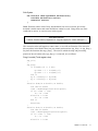
1.3.7 Writing Our First Rule
Let’s try writing our first rule in Agt_Step{}.
ForwardX() is a function which moves the agent in the direction of the X axis by the
amount specified in the argument.
Prog02.model (Turtle agent rules)
Agt_Step{
ForwardX (1)
}
Step:
artisoc simulations are run in units of time called “steps”. artisoc executes the
Agt_Step{} (execution rules) of every agent included under Universe, in random order,
and when these end, the step count is increased by one.
1.3.8 Running a Simulation (Bullet Turtle)
When you finish writing the rule, try clicking the Start button in the Run Panel. If an
error occurs, find and correct errors in the highlighted line.
If the simulation runs properly, the value of the X coordinate of the agent increases by
one at every step. So the turtle, which started in the left-hand corner, will move to the
right-hand corner and stop moving due to the dead end of the space. The simulation
itself appears to be stopped, but the turtle repeats the attempt to move at every step of the
simulation.
Click the Stop button to stop the simulation. Select File > Save As on the menu bar, and
save the model as “prog02.model”.
16
artisoc User Manual
1.3.9 Creating an Agent which Moves Back and Forth on the Map
(1) Add a Variable in the Agent
Let’s try modifying the bullet turtle to move back and forth on the two-dimensional map.
Think for a moment about how the rule should be changed. Basically, what we want is
“If a end of map is reached, change direction”, however, with just the agent’s X and Y
coordinates we cannot ascertain its direction (and here we don’t use the Direction
variable to control direction).
In light of this, we will add to the turtle agent a new variable, which uses positive and
negative values to indicate the direction in which the turtle is advancing. Select the
Turtle in the component tree, and right-click to display the context menu. Select Add
Variable from the menu to display Variable Properties dialog . Set the Variable Name to
“DIRX”, Variable Type to Integer, and Dimensions to 0. Click OK.
(2) Add a Conditional Branching Rule
Let’s try writing out the rules before expressing them in code.
• Initial rule: Set DIRX to 1
• Execution rule:
If the return value of ForwardX is not −1, consider the turtle agent to reach the
dead end and multiply DIRX by −1.
Converting these rules to code results in the following.
Prog03.model (Turtle agent rules)
Agt_Init{
My.DIRX = 1
}
Agt_Step{
If ForwardX(My.DIRX) <> -1 Then
My.DIRX = My.DIRX * (-1)
End If
}
When you type “My.”, variables menu to select X, Y, Direction, etc. is displayed. Here
we use DIRX, so select DIRX using the arrow keys and press Enter. This “My.” is a
special expression which refers to the agent itself. Therefore “My.DIRX” indicates the
DIRX variable which is contained in this agent itself.
To make the code easier to read, you should place spaces between variable names and
operators such as ‘=’, ‘+’, and ‘−’.
“My.” is a special expression to indicate an agent itself.
artisoc User Manual
17
“=” in a rule is an assignment operator.
As mentioned above, Agt_Init{} is a rule which is executed once when an agent is
created. The new variable are set to 0 as its initial state, so if DIRX is not set to 1 or −1
in the initial rule, the turtle will not be able to move.
In the prog03.model, a conditional branching rule is newly added. It is written with the
following syntax: If (condition) Then (rule to perform if the condition is true) End If.
Any number of lines can appear between the “Then” and the “End If”. It is common to
use Tab to indent this portion in order to make the branched structure of the conditional
expression easy to read.
In rule declarations, no distinction is made between upper and lower case characters.
Consequently, “my.DIRX” and “My.dirx” are actually both treated identically.
If (condition) Then (rule for when the condition is true) End If
In rule declarations, no distinction is made between upper and lower case characters.
(3) Run a simulation (back-and-forth turtle)
After you finish writing the rule, try clicking the Start button in the Run Panel. If the
simulation runs properly, the turtle will switch direction at the end of the map, and move
back and forth between the left end and the right end. Select File > Save As, and save the
model as “prog03.model”.
As a practice exercise, try adding a variable DIRY which represents the direction for the
Y coordinate, and creating an agent which moves diagonally. The correct answer for the
agent rules is as follows.
Prog04.model (Turtle agent rules)
Agt_Init{
my.DIRX = 1
my.DIRY = 1
}
Agt_Step{
If ForwardX(My.DIRX) <>
My.DIRX = My.DIRX *
End If
If ForwardY(My.DIRY) <>
My.DIRY = My.DIRY *
End If
}
-1 Then
(-1)
-1 Then
(-1)
Select File > Save As, and save the model as “prog04.model”.
18
artisoc User Manual
1.3.10
Increasing the Number of Turtle Agents
(1) Create multiple agents
When you have successfully created an agent which moves diagonally, let’s next try
creating multiple agents. No matter how many of them we create, if they are all initially
placed in the same location, they will all move in the same way. We will thus vary the
location at which every agent is placed.
Select the Turtle agent in the component tree, and right-click to display the context menu.
Select Properties to display Agent Properties dialog. Set the Agent Count to 3, and click
OK.
The agent count is set using Agent Properties.
(2) Provide agents with initial locations individually
We want to start the respective agents from different locations. What do we need to do in
order to provide separate initial values to the X and Y variables representing the agents’
locations in the space?
Variables have the ability to have initial values individually, so we will be using this
functionality. Select the variable X under the Turtle agent in the component tree, and
right-click to display the context menu. Select Initial Values to display Initial Values of
Variables dialog.
Three turtle agents — numbers 0, 1, and 2 — are listed. Give these the values 5, 10, and
15, respectively, as shown in the following screenshot. If the numbers are hard to see,
drag the right edge of gray column header X to adjust the width of the column. After you
have entered these settings, click OK to close the dialog. You will see that, despite the
simplicity of the rules, the movements which result are quite interesting.
artisoc User Manual
19
Agents are given initial values individually using Initial Values of Variables dialog.
(3) Provide agents’ variables with a single value other than 0 at once
Next, let’s say that we want to start all of the agents from a Y coordinate of 5. What can
we do to accomplish this? There are two answers to this. One is to right-click the
variable Y, select Initial Values, and set the value of Y for all three agents to 5. The other
is to add “my.Y = 5” to Agt_Init{} in the same manner as was already described for
setting DIRX.
Select File > Save As, and save the model as “prog05.model”.
20
artisoc User Manual
1.3.11 If the Simulation Does Not Run Properly
Component Placement and Settings
▼
Outputs Settings
▼
Agent Rule Declarations
▼
Run and Debug
The process of tracking down the cause of an error in a program and then fixing the
program so that it runs properly is called “debugging”. No matter how carefully your
programming may be, the program can hardly run perfectly on the first try. It is safe to
say that problems such as a program stopping due to syntax errors, a program exhibiting
unexpected behavior, etc. will always occur. No matter how proficient you may be,
oversights and slips are a fact of life in programming. Therefore you may ultimately
make quicker progress by appropriately solving the problems that inevitably occur,
rather than trying to prevent errors beforehand.
In contrast to human beings, who tend to be ambiguous about things, computers all run
by logic. Unless something quite unusual happens, exceptions deviating from logic do
not occur. As a result, it can be said that a computer error always has a clear cause. If the
results of a program are not as you expected, it is because there is some sort of problem
on logic, and not because, for example, “the machine is in a bad mood” or “the machine
hates me”.
To resolve errors, it is important to first track down and isolate, in accordance with the
logic of the computer, the area which has caused the problem. The followings are errors
which beginners are especially prone to make.
(1) Syntax errors in rules
When a program behaves differently from what was expected, or when a warning
appears, the first thing to suspect is syntax errors in the rules. These sorts of errors are
experienced often as a result of carelessness, and not only by beginners but by proficient
programmers as well.
Countermeasure 1: artisoc has a feature in which, when an error is found prior to run,
a warning is displayed indicating the line involved. In most cases the cause of the error
is a mistake in the code in the highlighted line, so check the followings.
• Spelling errors in variable or function names
• Appropriate spaces not inserted when writing statements, variables, and operators
The space between words in a program has an important significance. If words are
strung together they will not be recognized correctly.
Countermeasure 2: Check the values of variables using the “PrintLn” built-in
artisoc User Manual
21
function within rules.
For example, PrintLn(DIRX) will display the value of DIRX variable on the console
screen.
(2) Mistakes in output settings
In artisoc, if you don’t specify output settings then nothing will be displayed when you
run the simulation. Also, when two types of output are expected and only one appears, or
when a graph or value behaves in an unexpected way, this is often due to errors in the
output settings. In many cases, warnings are not displayed for these errors, so finding
these errors may be difficult at first.
Countermeasure: When you are trying to obtain some sort of result in the simulation,
the output settings are indispensable. In the respective output settings, check if the item
name and the element name in the element settings are correct. The reason why an
output element is missing is often an error in the element name.
(3) Mistakes in component properties
If nothing in particular is wrong with the rules, but the behavior is nevertheless unusual,
you should suspect that there may be an error in the component properties (agent count,
initial values, etc.).
Countermeasure 1: Check if the respective properties are set properly.
Countermeasure 2: There is more than one way to set the initial value of
components as follows.
• In Initial Values of Variables dialog, the values of individual components are set
separately
• Values can also be assigned using assignment statements in component rules
If you use both of the above methods of specifying initial values, the settings will be
prioritized in the following order: component rules, Initial Values of Variables dialog.
Try checking if a setting is being overwritten somewhere.
22
artisoc User Manual
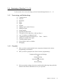
1.4 Summary of Section 1.1~1.3
In this section, let’s review the things you have learned through Section 1.1 ~ 1.3.
1.4.1
Terminology and Methodology
□
□
□
□
□
□
□
□
□
□
□
□
□
□
□
□
□
Component tree
Universe
Run Panel
Space
Agent
Variable
Adding a space under Universe
Adding an agent
Setting outputs
Opening the Rule Editor
Two types of rules (Agt_Init{} and Agt_Step{})
“my.” to indicate a component itself
Conditional branching declarations (If … Then … End If)
Adding an variable to the agent
Creating multiple agents
Giving initial values to variables
Debugging
1.4.2 Checklist
□
Were you able to understand the basic component elements in the artisoc
programming environment?
□
Were you able to grasp the basic flow for artisoc programming?
Component Placement and Settings
▼
Outputs Settings
▼
Agent Rule Declarations
▼
Run and Debug
□
Did you actually configure the artisoc models while following along with this
manual? And did the simulations run as you expected?
artisoc User Manual
23
1.5 Creating a Slightly Complicated Model
In this section, we will further modify the rules for the “back-and-forth turtle” we
worked with in Section 1.3, while adding gradually more complicated elements. In terms
of programming concepts, we will learn variable declaration, repetition control, random
numbers, functions, arrays, etc. Thus far the atmosphere has been somewhat mechanical,
but when we incorporate randomness into the rules, the agents will be able to move
randomly, which will result in more agent based model-like behavior. In addition, tips
for use in artisoc appear in a variety of places, so be careful not to miss them.
1.5.1 Resetting the Initial Values for X and Y
In Prog05.model, we have set the initial values of the X and Y variables, so now clear
them. Select the variable X from the tree, and right-click to display the context menu.
Select Initial Values and return the values to which the X variable has been set (5, 10,
and 15) back to 0. Also, return the initial values for the variable Y to 0.
1.5.2 Using the Universe
If there are a large number of agents (for instance, 100 or 200), how can we assign them
with initial values in an efficient manner? If the agents are to be placed in a regular
fashion, it would seem effective to write a rule somewhere. However, in the rules for
agents, it is impractical (or, more accurately, is structurally unnatural) to define global
information for multiple agents, although local information about such as an agent itself
and its surroundings can be set. In such cases, we can use Universe at the top of the tree.
Since the Universe is an agent, rules can be declared for it. Rules for Universe are often
used to survey the agents under Universe and then perform batch processing on them.
Rules for Universe are often used to perform batch processing on the agents under it.
Now let’s consider the case in which the turtle agents are to be placed on every third
location along the X axis. What we need in rules for Universe is to know the number of
turtle agents created, and to assign values to the X variables of the respective agents. We
will write this into the initial rule of Universe.
Prog06.model (Universe rules)
Univ_Init{
Dim i as integer
for i = 0 to CountAgt(Universe.Space1.Turtle) - 1
Universe.Space1.Turtle(i).X = i * 3
next i
}
The statements in this code are explained in the following subsections. Select File >
24
artisoc User Manual
Save As, and save the model as “prog06.model”.
1.5.3
Initially Declaring Variables Used Only Within the Rule
The first item to appear is a “Dim” statement. This is called a declaration statement, and
is used to declare name and type of temporary variables which are used only within that
rule. When the rule has finished executing, these variables are deleted. These are called
local variables, and their use is distinct from that of variables in the component tree,
which hold values at all times. Here, an Integer variable “i” is defined in order to specify
individual agents.
“Dim” statement is used to declare temporary (local) variables used only within in a rule.
1.5.4 Repetition Control
The next item to appear is a “For … Next” statement called a repetition control
statement. This repeats the statements contained in it the specified number of times. The
number of times to perform the repetition is defined as follows.
for <variable name> = <initial value> to <final value> step <increment>
<items to repeat>
next <variable name>
Since the repetition statement’s variable “i” is usually increased by 1 each time, if “step”
is omitted, then increment is treated as 1. If the step value is −1, the variable will be
decreased by 1 each time. To make the structure easy to read, indent the items to be
repeated by Tab.
1.5.5 Determining the Number of Agents Created
To determine the number of agents which have been created, CountAgt(), a function
provided in artisoc, is used. Functions are roughly equivalent to those in mathematics.
When data is supplied to a function, the function returns a specific return value (result).
There are built-in functions pre-defined in artisoc, and original functions can be defined
by the user as well. For CountAgt(), if an agent (Turtle) is specified within the
parentheses, the number of the agents (copies of Turtle) will be returned as an Integer.
Function are a mechanism in which data is supplied and a specific value is returned.
1.5.6
Specifying a Component
In terms of how an agent is specified within the parentheses, the hierarchical relationship
with respect to Universe is expressed delimited by periods. The Turtle agent will be
“Universe.Space1.Turtle”. This sort of expression is used in a variety of places, so be
artisoc User Manual
25
sure to remember it.
To specify a component, describe its hierarchical relationship with respect to Universe.
Periods indicate hierarchical relationships.
1.5.7 Accessing Individual Agents
A simple technique is necessary to obtain the information held by an individual agent.
This sort of expression is used frequently, so be sure to remember how to use it.
First, created agents are allotted array number sequentially starting with 0. The variables
in agents are stored as an array, and are called up in the form “variable_name (array
number)”. For example, the X coordinate of the turtle agent with an array number of 4 is
represented as “Universe.Space1.Turtle(4).X”. In prog06.model, the variable “i”
represents array number by changing its value from 0 to agent count −1, and each
respective X coordinate is assigned a value of i×3.
Agent’s array number are allotted sequentially starting from 0.
Array variable:
When a large amount of data must be handled at one time, giving a name to each item is
extremely cumbersome. For example, if you are assigning variables to the test scores of
10 people in 5 subjects, creating a number of variables equal to the product of the
number of people and the number of subjects — e.g.,
En1, Ma1, Hi1, So1, Sc1
En2, Ma2, Hi2, So2, Sc2
:
would be exceedingly inefficient, and moreover, if the number of people were to change,
this system would be unable to support the change.
In such situations, array variables are used. Array variables can be handled in the form
“variable_name (array number)” with an array number simply provided in the
parentheses. In the example with test scores for 5 subjects, this would be
En(1), Ma(1), Hi(1), So(1), Sc(1)
En(2), Ma(2), Hi(2), So(2), Sc(2)
:
By employing this method, we can use variable “i” with a repetition statement such as
“For … Next”.
En(i), Ma(i), Hi(i), So(i), Sc(i)
26
artisoc User Manual
In artisoc, the variables held by agents automatically become array variables. In addition,
if variables are added to the space, a grid-shaped three-dimensional array which
conforms with the size of the space is created. A three-dimensional array is specified as
“variable_name (X_coordinate, Y_coordinate, Layer)”.
1.5.8 Running a Simulation (Many Uniformly Arranged Turtles)
Now let’s try running a simulation with an agent count of, let’s say, 6. You will see that
the turtle agents line up in a uniformly spaced manner, as specified in Univ_Init{}.
1.6 Giving an Agent a Randomness
Based on what you’ve done so far, we trust that you now understand the way of giving
variables uniformly varying values. However, this still seems somewhat mechanical and
not quite multi-agent-like. In light of this, let’s next try adding a randomness to the
initial rule.
1.6.1 Randomly Arranging Agents in the Space
It is a relatively simple matter to randomly arrange agents in the space. We will use the
agent function RandomPutAgtSetCell(), which is already provided in artisoc, in
Univ_Init{}. In the parentheses, we will set the first argument to be the agent to be
placed, the second argument to be either True or False to indicate whether or not to
permit multiple agents to be placed in a single cell. You may assume you should write
the assignment statement such as “i = RandomPutAgtSetCell()”, because functions by
nature have return values. However, in this case only the capability to randomly arrange
the agents is important, so the return value is not necessary. When the return value will
not be used, the assignment expression is often omitted, as is the case in the rule below.
RandomPutAgtSetCell() arranges agents randomly.
Prog07.model (Universe rules)
Univ_Init{
Dim TurtleSet as AgtSet
MakeAgtSet(TurtleSet, Universe.Space1.Turtle)
RandomPutAgtSetCell(TurtleSet, False)
}
A set of turtles in the space is defined as “TurtleSet”, and the initial values of TurtleSet
are obtained using MakeAgtSet(). Subsequently obtained agent set (TurtleSet) is
arranged randomly by RandomPutAgtSetCell().
Select File > Save As, and save the model as “prog07.model”.
artisoc User Manual
27
1.6.2 Adding Randomness to Variable Values
To assign a random number to a variable, we use the Rnd() function. Rnd() generates a
random number which is greater than or equal to 0, and less than 1. A random number
which is an integer is often required, so the method below, in which Int() is used to
truncate the decimal part, is employed.
i = Int(Rnd() * 5)
In this case, the value of the variable “i” will be an integer value from 0 to 4. If you want
to obtain a value from 1 to a, you can use the following statement.
i = Int(Rnd() * a) + 1
In the previous example, if RandomPutAgtSetCell() is not used, you can write the
Univ_Init{} as follows.
Prog08.model (Universe rules)
Univ_Init{
Dim i as integer
For i = 0 to CountAgt(Universe.Space1.Turtle) - 1
Universe.Space1.Turtle.X(i) = Int(Rnd()*50)
Universe.Space1.Turtle.Y(i) = Int(Rnd()*50)
Next i
}
Select File > Save As, and save the model as “prog08.model”.
To obtain a random integer from 0 to a: i = Int(Rnd() * (a + 1))
In addition to this, let’s also try imparting a random direction to the agents. We will first
need to remove the initial rule which has been left in the Turtle agent.
In the following rules, the complicated expression “−1 + (Int(Rnd() * 2) * 2)” appears.
This is just a simple technique for obtaining a result of either −1 or 1.
Prog09.model (Universe rules)
Univ_Init{
Dim i as integer
For i = 0 to CountAgt(Universe.Space1.Turtle) - 1
Universe.Space1.Turtle.X(i) = Int(Rnd()*50)
Universe.Space1.Turtle.Y(i) = Int(Rnd()*50)
Universe.Space1.Turtle.DIRX(i) = -1 + (Int(Rnd()*2) * 2)
Universe.Space1.Turtle.DIRY(i) = -1 + (Int(Rnd()*2) * 2)
Next i
}
28
artisoc User Manual
Prog09.model (Turtle agent rules)
Agt_Init{
}
Select File > Save As, and save the model as “prog09.model”.
1.6.3 Rewriting Execution Rules of the Agent
We now have a program in which the initial location and direction of agents is provided
randomly. Next, as an application of this, let’s try also adding a randomness to the
agents’ execution rule (Agt_Step{}). Right now an agent’s direction does not change
until it reaches the end of space, so let’s instead try changing the direction randomly.
Prog10.model (Turtle agent rules)
Agt_Step{
if Int(Rnd()*10) == 0 then
my.DIRX = -1 + Int(Rnd()*3)
my.DIRY = -1 + Int(Rnd()*3)
end if
If my.X <= 0 Then
my.DIRX = 1
End If
If my.X >= 49 Then
my.DIRX = -1
End If
ForwardX (my.DIRX)
If my.Y <= 0 Then
my.DIRY = 1
End If
If my.Y >= 49 Then
my.DIRY = -1
End If
ForwardY (my.DIRY)
}
In this Turtle agent’s execution rule, a rule which randomly changes the direction is
placed before the determination as to whether the end of space has been reached.
Since changing direction every step would result in a sort of drunken stagger, the “If”
statement is set up such that there is a one in ten chance that the direction will be
changed. In addition, unlike the previous examples, the “If” statements here obtain a
value of −1, 0, or 1. In this way, agents will be seen to occasionally stand still.
To cause a branch with a probability of 1 in A: If Int(Rnd()*A) == 0 Then … End if
Select File > Save As, and save the model as “prog10.model”.
artisoc User Manual
29
1.7 Creating a Spacing that Loops
Looped space is a coordinate system which is utilized in LOGO’s turtle graphics. The
top and bottom of the map, and the right and left of the map, are connected, so that, for
example, an agent which disappears off the right side of the map will reappear on the left
side. This coordinate system is convenient in that it can represent a pseudo-spherical
space, but handling it in artisoc requires a bit of trickery. We will describe the procedure
and rules for a looped space.
Thus far in progXX.model, “If” statements have been incorporated in order to change
direction when a end on the map has been reached, but now, with the space being
configured to loop, this map end processing will be taken out.
1.7.1 Configuring Space
First of all, you can select Loop or Don’t loop in the Space Properties dialog. To cause
looping, Loop must be selected. However, this will only be in effect for space
manipulation functions which have already been pre-defined, and therefore the
preparations for a looped space are still not sufficient.
To loop the space, Loop setting in the Space Properties dialog is not sufficient.
1.7.2 Creating Coordinate Location Correction Functions
We will need to provide rules which correct agents’ coordinate locations. However, since
the rules themselves have gradually grown larger, and since this correction rules seem to
have the potential for reuse elsewhere as well, let’s try making use of user-defined
functions.
Function and Sub are functions that allow you to freely define the user-defined functions.
The use of Function and Sub is differentiated as follows.
• If a return value is required: Function
• If a return value is not required: Sub
Function Syntax
Function <function name>(<parameter declarations>) As <type of return
value>{
<variable declarations section>
<execution section>
Return(<expression>)
}
30
artisoc User Manual
Sub Syntax
Sub <function name>(<parameter declarations>){
<variable declarations section>
<execution section>
}
Note: Function names can be freely denominated, but reserved words, previously
declared variable names and name definitions cannot be used. Using these can cause
confusion in artisoc, so exercise care in this regard.
User-defined function:
Function <function name>(<argument> As <argument type>) As <return value type> { }
The correction rules will require a return value, so we will use Function. You can write
this anywhere in the Rule Editor, but you cannot put them into Agt_Init{} or Agt_Step{}.
So place the function after Agt_Step{}. The rules in which the map end processing
portion of the execution rule (Agt_Step{}) is removed, are as follows.
Prog11.model (Turtle agent rules)
Agt_Init{
}
Agt_Step{
if Int(Rnd()*5) == 0 then
my.DIRX = -1 + Int(Rnd()*3)
my.DIRY = -1 + Int(Rnd()*3)
end if
my.X = FixX(my.X + my.DIRX)
my.Y = FixY(my.Y + my.DIRY)
}
Function FixX(iX as double) as double{
Dim LimX as double
LimX = GetWidthSpace(Universe.Space1)
If iX > LimX - 1 then
iX = iX - LimX
ElseIf iX < 0 then
iX = iX + LimX
End If
Return(iX)
}
Function FixY(iY as double) as double{
Dim LimY as double
LimY = GetHeightSpace(Universe.Space1)
If iY > LimY - 1 then
iY = iY - LimY
ElseIf iY < 0 then
artisoc User Manual
31
iY = iY + LimY
End If
Return(iY)
}
Select File > Save As, and save the model as “prog11.model”.
There are functions in “Function FixX” and “Function FixY” with which you are as yet
unfamiliar. GetWidthSpace() and GetHeightSpace() are functions used to obtain the
width and height, respectively, of the space. Using these will allow us, for example, to
change the size of the space at any time without having to change the rules.
Setting program up such you use functions to obtain values — even constant values
which are supplied once and do not change — which might be changed via properties,
will serve to increase the generality of your rules and also decrease errors.
GetWidthSpace() obtains the width of the space.
GetHeightSpace() obtains the height of the space.
As an application of these, try rewriting the code from Subsection 1.6.1 for randomly
arranging agents, using GetWidthSpace() and GetHeightSpace().
1.8 Summary of Section 1.4~1.7
In this section, let’s review the things you have learned through Section 1.4 ~ 1.7.
1.8.1
Terminology and Methodology
□
□
□
□
□
□
□
□
□
□
□
□
□
□
□
32
artisoc User Manual
Using Universe rules
Dim statement
Repetition control (For … Next statement)
Functions
CountAgt()
Specifying a component hierarchically
Agent’s array number
Array variables
RandomPutAgt()
Obtaining random integers from 0 to a
Branching with a probability of 1 in A
Looping the end of space
User-defined functions: Function
GetWidthSpace()
GetHeightSpace()
1.8.2 Checklist
□
Were you able to read and comprehend what sorts of processing will be
performed in the above example programs?
□
Try changing the value of the variables in the example programs, and consider
potential applications of them.
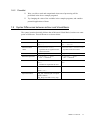
1.9 Syntax Differences between artisoc and Visual Basic
The syntax in artisoc basically follows that of Microsoft Visual Basic, but there are some
points of difference. These differences are shown below.
Item
artisoc
Visual Basic
Function definitions
Function{...}
Sub{...}
Function ... End Function
Sub ... End Sub
Function return
values
Return(<return value>)
Specified as an argument to the
Return function
<function name> = <return value>
Inputted to function name
Variable declarations
Type is required
If type not specified, Variant
Relational operators
If A==B Then ... EndIf
Two ‘=’ characters
If A=B Then ... EndIf
One ‘=’ character
For … Next
For i=0 To 10
Next i
Variable is required at the end
For i=0 To 10
Next
Comments
'...
//...
From /* to */
'...
Special functions
Agt_Init: executed just once upon
agents creation
Agt_Step: executed at every step
artisoc User Manual
33
Chapter 2
Reference
artisoc User Manual
35
2.1 Model Configuration
In this section, we will describe the model configuration capabilities, which are used to
configure components such as agents and variables.
2.1.1
Model File Input/Output
To perform such tasks as creating new simulation models, loading existing simulation
model files, and saving simulation settings which have been created, select a command
from the File menu, as shown in the screenshot below. Simulation configuration data is
saved as a model file (*.model).
Creating a New Simulation Model
To newly configure a simulation model, select File > New.
Loading a Simulation Model
To load a model file, select File > Open.
Saving a Simulation Model
To save a configured simulation as a model file, select File > Save or Save As.
36
artisoc User Manual
2.1.2 New Model Creation
When you start up the artisoc, or select File > New, a screen such as the following is
displayed.
Tree
Tree window is the most basic screen in the artisoc, which displays the various
components in a tree structure. In the tree, there will always be one Universe. The
simulation model is configured by placing components such as spaces, agents, and
variables under this.
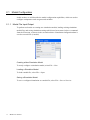
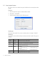
2.1.3 New Space Creation
A space is a flat surface. It is created in order to observe agents moving there.
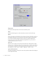
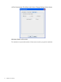
Procedure
1.
Select Universe in the tree.
2.
Select Insert > Add Space.
3.
Space Properties dialog such as the following is displayed.
artisoc User Manual
37
Space name
Is the name of this space. You can enter an arbitrary name, for example, “Space1”.
Space type
Selects a space type. You can select either Grid model or Hexagon model.
Space dimensions
Is set to 2 to signify two-dimensional space.
Space size, Layer
Sets the size of the space. Space size can be regarded as the number of cells in the grid
on which agents occupy or move. Specify the maximum X (cells in the horizontal
direction) and Y (cells in the vertical direction) coordinate, and layer count. The default
values are 50 × 50 × 1.
End of space
If Loop is checked, then when a component reaches a end of the space, it will appear on
the opposite end. If Don’t Loop is checked, the component will stop at the end of the
space.
4.
38
Click the OK button. The dialog closes, and the new space appears in the tree.
artisoc User Manual
Thus, we have successfully configured a space directly under Universe.
Note: A space can only be created directly under Universe. This specification serves to
make the environment conceptually easy to understand.
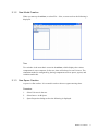
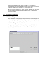
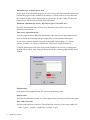
2.1.4 New Agent Creation
We will next create a new agent. Unlike spaces, agents can be created under Universe,
spaces, or other agents in the tree. The following procedure is an example that the agent
is created under the space.
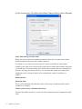
Procedure
1.
Select a space (here, Space1) in which to create the agent.
2.
Select Insert > Add Agent.
3.
An Agent Properties dialog such as the following appears.
Agent name
Is the name of this agent. You can enter an arbitrary name, for example, “Agent1”.
Agent count
Is the number of instances of this agent. When you run simulation, the specified number
of agents are created, and they behave based on the same rules. Think as “How many
copies of this agent should be created?”.
artisoc User Manual
39
4.
Click the OK button. The dialog closes, and the new agent appears in the tree.
Thus, we have successfully created a new agent under the space. The process is the same
even when creating a new agent directly under Universe, or when creating a new child
agent under another agent.
Note: When an agent is placed in a space, four variables — X, Y, Layer, and Direction
— are automatically placed under the agent, because agents always have coordinate
information in the space.
2.1.5 Agent Rule Declaration
Even after an agent is created, it will not do anything if no rules are written for it. It is
necessary to create agent rules for each agent.
Procedure
1.
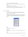
Select the agent and open the Rule Editor.
There are two types of Rule Editor window — Rule Editor for Universe in which rules
for Universe are written, and Rule Editor for agents in which rules for agents are written.
To open Rule Editor for agents, select the agent and either select View > Rule Editor, or
right-click the agent and select Rule Editor. A window such as the following will open.
40
artisoc User Manual
2.
Write agent rules within this window.
• Between the { and } of Agt_Init, write a rule which is to be executed once when
the agents are created.
• Between the { and } of Agt_Step, write a rule which is to be executed at every step
in the simulation.
For Universe, four types of special rules can be written.
• Between the { and } of Univ_Init, write a rule which is to be executed once at the
beginning when the simulation starts.
• Between the { and } of Univ_Step_Begin, write a rule which is to be executed at
the beginning of every step in the simulation.
• Between the { and } of Univ_Step_End, write a rule which is to be executed at the
end of every step in the simulation.
• Between the { and } of Univ_Finish, write a rule which is to be executed once at
the end when the simulation stops.
Note: Traditionally multi-agent simulators have a drawback that simulations cannot be
constructed without first learning an extremely complicated programming environment.
artisoc was developed with this issue in mind. However in order to create simulation
models, programming the rules is inevitable. You can learn more about these rules by
referring for instance to the sample models.
The syntax which are used by artisoc are similar to that in Microsoft Visual Basic,
which is relatively easy to learn. For information on artisoc syntax, see Section 1.9 and
Chapter 3.
artisoc User Manual
41
Find and Replace in Rule Editor
With the Rule Editor open, when Edit > Find or Replace is selected, the Find or Replace
dialog opens.
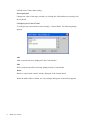
Rule Editor Configuration
By selecting Settings > Other Settings, settings for the Rule Editor can be changed.
Auto-indent
If this item is checked, automatic indentation will be performed when entering rules in
the Rule Editor.
42
artisoc User Manual
Coloration
If this item is checked, coloration will be performed when entering rules in the Rule
Editor. To improve the response of your Rule Editor, uncheck this.
Font
If you want to change the font settings in Rule Editor, click Font button. The Font
Settings dialog is displayed.
Keep output screen open after simulation
(This setting is not for the Rule Editor.) If this checkbox is unchecked, the output
windows will be deleted when the simulation stops.
The auto-indent, font, etc. which have been specified here are immediately reflected in
the display of the Rule Editor.
2.1.6 Agent Deletion
To delete a agent, select the agent that you want to delete and either select Edit > Delete,
or right-click the agent and select Delete.
artisoc User Manual
43
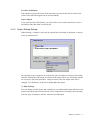
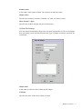
2.1.7 New Variable Creation
We will next create a new variable in the agent. Variables can be created anywhere under
an agent.
Procedure
1.
Select the agent (here, Agent1) to which to add the variable.
2.
Select Insert > Add Variable.
3.
Variable Properties dialog such as the following opens.
Variable name
Is the name of this variable. You can enter an arbitrary name, for example, “Variable1”.
Variable type
A type must be selected which conforms to the data stored in this variable. The types are
as follows.
Type
44
Type Name
Value Range
Boolean
Boolean
Returns True if true, or False if false
String
String
Character count is 0 to no limit
Integer
Integer
Integer from −2,147,483,648 to 2,147,483,647
Long integer
Long
Integer from −9,223,372,036,854,775,808
to 9,223,372,036,854,775,807
Real number
Double
If negative:
−1.79769313486232×10308 ~ −4.94065645841247×10−324
If positive:
4.94065645841247×10−324 ~ 1.79769313486232×10308
Agent type
AgtType
Type of agent defined in the model tree
Agent
Agt
An agent itself. Actual value of agent
artisoc User Manual
Agent set
AgtSet
Set of agents
Space
Space
Name of space defined in model tree (Space height and width:
1 ~ 10,000)
Basically, we recommend choosing the String for characters, the Integer for integers, and
the Double for values with a decimal part. The Boolean is a somewhat special type, and
its values are either yes (True) or no (False).
The Agt is used when you want to use an agent itself as an argument to a function, and
the AgtSet is a collection of that object type.
History size
In the artisoc, past states (values) of variables can be recorded. Using this field, you can
specify the number of steps to be recorded. Past states can be retrieved using the
GetHistory function. The maximum history size is 10,000 steps.
Dimensions
A variable is like a box into which data is placed. As a general rule, only a single value
can be placed into a single variable. A newly created variable has 0 dimensions (in other
words, it corresponds to a point on a planar surface), and can store one value. However,
this makes it inconvenient to handle a large amount of the same type of values. By
increasing the number of dimensions, you can increase the number of values which can
be stored.
A one-dimensional variable can store (n+1) values — from 0 to the value (n) specified
for Array Elements Count of N Dimension. A two-dimensional variable with an array
elements count of m for the first dimension and n for the second dimension can store
(m+1) × (n+1) values (which is expressed as “variable (m, n)”).
The array element starts from 0, so be sure to add one to the elements count. The
maximum number of dimensions and maximum array elements count are 10,000.
4.
Click the OK button. The dialog closes, and the new variable appears in the tree.
Note: When an agent is created in a space, variables ID, X, Y, Layer, and Direction are
artisoc User Manual
45
automatically created. ID variables indicate the number (0 or more) applied to
distinguish agent's each one by each agent type. Other variables indicate the coordinates
of the agent and therefore are not created if the agent is not in a space.
We have successfully created the new variable “Variable1” under the agent. The creating
process is the same even when creating directly under Universe, or when creating
directly under a space.
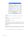
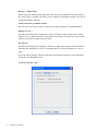
2.2 Simulation Configuration
2.2.1
Initial Values Dialogs
These dialogs set the initial value of each component. Selecting a component in the tree
and then selecting Settings > Initial Values will open the initial values dialog for the
component. The dialog will vary depending on the type of component that was selected.
Initial Values Dialog for Agents and Variables
If an agent or a variable is selected in the tree, and then Settings > Initial Values is
selected, the following dialog (here, Initial Values of Agents dialog) is displayed. In
these dialogs, the initial values of the agent or the variable at the beginning of the
simulation can be set.
46
artisoc User Manual
Set values individually
If the number of agents has been set to more than one, then if this item is checked, the
values of the individual agents can be set individually.
Export, Import
If you click the Select File button, you will be able to save initial value data to a file or
load initial value data from an existing file.
2.2.2
Output Setting Dialogs
When Settings > Outputs is selected, the Output Item List dialog is displayed, as shown
in the screenshot below.
By selecting a type of output to be set from the Type of Output to Add list in this dialog,
and then clicking the Add button, the details of the output can be set. If multiple outputs
are necessary, repeat this procedure. Using the arrow icons, the output order can be
changed. Use checkboxes in the list to display/hide that output.
(1) Map Settings
You can display specific agents and variables on a two-dimensional map and observe the
agents’ movement and increase/decrease. In the Output Item List dialog, select the Map
from the Type of Output to Add list, and click the Add button.
artisoc User Manual
47
Space name
Specifies the space to be displayed.
Layer
Specifies the layer to be displayed. If the Layer field in the Space Properties dialog has
been set to 1, you cannot set to the value other than 0. If the Layer field in the Space
Properties dialog has been set to greater than 1, you can set to the value from 0 to that
value − 1.
Map name
Is the name to reference when calling up this map.
Map title
Is displayed in the map window.
Show legend
If this is checked, a legend is displayed beside the map.
48
artisoc User Manual
Show ruled-lines
If this is checked, horizontal and vertical lines are drawn on the map.
Background image
If this is checked, the map is displayed against a background image. Specify the image
either by checking Filename and entering the path (relative path from the folder in which
the model file is placed), or by checking Variable Specifying Image File and selecting
the variable (string variable immediately under the Universe).
Origin location
Selects whether to position the origin in the upper left, as is common in computer or
information science, or in the lower left, as is common in mathematics.
View type
Selects whether to place each agent within a cell (Chess type), or on the point of
intersection (Go type).
X axis, Y axis
By setting minimum and maximum values, it is possible to display only a specific
portion of the space on the map. The default maximum value is the space size.
Map element list
Lists the agents and variables displayed on the map. When the Add button in the Map
Element List area is clicked, the following dialog is displayed to set the element of this
map.
If you want to display multiple elements on the map, each of them (e.g., Agent1, Agent2,
Variable1, etc.) must be added to the Map Element List.
Using the Edit button in the Map Element List area, any existing map element can be
edited. Also, using the Delete button, any existing map element can be deleted.
artisoc User Manual
49
Element name
Is the name of this map element. You can enter an arbitrary name.
Target
Selects the element (agent etc.) whose movement you want to watch on this map.
Marker
Selects what marker to be displayed for the element on the map. With None, a marker is
not displayed. With Select, you can select one of the built-in markers. With Filename,
you can select an arbitrary image file (only icon files are currently supported) by
entering the path to the file. With Variable Specifying Maker File, you can select a
variable immediately under the Universe.
Agent color
Selects the color of agents. You can select either Fixed color, which specifies a single
arbitrary color, or Variable Specifying Color, which specifies a variable to determine the
color. The latter can change the color dynamically. The default agent colors are, in the
order added, red → blue → green → purple → light blue → yellow → grey.
Agent variable information
If the Show Information is checked, the value of the specified variable will be displayed
over the agent on the map.
50
artisoc User Manual
Draw lines
If the output target agent has an agent set variable then the output target agent and the
respective elements in the agent set can be connected with a line. The line type, arrow,
etc. for the line can be selected.
(2) Time Series Graph Settings
You can display specific components in a time series line graph. In the Output Item List
dialog, select the Time Series Graph from the Type of Output to Add list, and click the
Add button.
Graph name
Is the name to reference when calling up this graph.
Graph title
Is displayed in the graph window.
Show legend
If this is checked, a legend is displayed beside the graph.
Axis label (for X axis and Y axis)
Is displayed as the label for the axis.
artisoc User Manual
51
Maximum steps to display (for X axis)
As the steps of the simulation progress, the time series graph is horizontally compressed,
because the graph window width does not change. If a step count is set here, then only
this number of steps will be displayed at any given time. In other words, old data will
progressively fall off of the left edge and be discarded.
Minimum, Maximum (for Y axis), Step interval (for X axis and Y axis)
Specifies the minimum value of the Y axis, maximum value of the Y axis, and
graduation step interval.
Time series graph element list
Lists the target elements. When the Add button in the Time Series Graph Element List
area is clicked, the following dialog is displayed to set the element of this graph.
If you want to display multiple elements on the graph, each of them (e.g., Agent1,
Agent2, Variable1, etc.) must be added to the Time Series Graph Element List.
Using the Edit button in the Time Series Graph Element List area, any existing graph
element can be edited. Also, using the Delete button, any existing graph element can be
deleted.
Element name
Is the name of this graph element. You can enter an arbitrary name.
Output values
Specifies the elements (variable etc.) whose progression you want to watch in this graph.
Line width, Line color
Sets the width and color of the line. The default line colors are, in the order added, red
→ blue → green → purple → light blue → yellow → grey.
52
artisoc User Manual
Show markers
If this is checked, markers will be displayed on the graph.
(3) Bar Graph Settings
You can display specific components in a bar graph. In the Output Item List dialog,
select the Bar Graph from the Type of Output to Add list, and click the Add button.
The settings are basically the same as those for the time series graph.
(4) Values Screen Settings
You can display the values of the specified components in a window. In the Output Item
List dialog, select the Values Screen from the Type of Output to Add list, and click the
Add button.
artisoc User Manual
53
Output name
Is the name to reference when calling up this output.
Values title
Is displayed in the values window.
Values element list
Lists the target elements. When the Add button in the Values Element List area is clicked,
the following dialog is displayed to set the element of this output.
If you want to display multiple elements on the screen, each of them (e.g., Agent1,
Agent2, Variable1, etc.) must be added to the Values Element List.
Using the Edit button in the Values Element List area, any existing element can be edited.
Also, using the Delete button, any existing element can be deleted.
54
artisoc User Manual
Element name
Is the name of this output element. You can enter an arbitrary name.
Output values
Specifies the elements (variables, formulas, etc.) that you want to watch.
Show decimal ... digits
Specifies the number of digits after the decimal point.
(5) Data File Settings
You can extract the simulation data of the specified components to a file. In the Output
Item List dialog, select the Data File from the Type of Output to Add list, and click the
Add button.
Output name
Is the name to reference when calling up this output.
Filename
Specifies the name of the file to which to output.
artisoc User Manual
55
Write at every ... steps
Specifies the simulation step interval to output.
Delimiter
Selects the delimiter character for the output data.
Data file element list
Lists the target elements. When the Add button in the Data File Element List is clicked,
the following dialog is displayed to set the element of this output.
If you want to extract the data of multiple elements to the file, each of them (e.g., Agent1,
Agent2, Variable1, etc.) must be added to the Data File Element List.
Using the Edit button in the Data File Element List area, any existing element can be
edited. Also, using the Delete button, any existing element can be deleted.
Element name
Is the name of this output element. You can enter an arbitrary name.
Output values
Specifies the variables that you want to extract.
Show decimal ... digits
Specifies the number of digits after the decimal point.
56
artisoc User Manual
2.2.3 Run Preferences Dialog
In this dialog, the various settings for running a simulation are defined. Select Settings >
Run Preferences to display the Run Preferences dialog. There are two tabs — Simulation
tab, Rule Execution tab and Multi Execution tab — in this dialog.
(1) Simulation Tab
Run for ... steps
Specifies the number of steps for which artisoc runs before it stops the simulation. You
can stop the simulation by clicking the Stop button in the Run Panel, before the number
of executed steps reaches this value.
Run for ... minutes
Specifies the number of minutes for which artisoc runs before it stops the simulation.
You can stop the simulation by clicking the Stop button in the Run Panel, before the
amount of time reaches this value.
Stop conditions
Specifies the conditions that artisoc stops the simulation. You can stop the simulation by
clicking the Stop button in the Run Panel, before this conditions are satisfied.
artisoc User Manual
57
Wait for ... milliseconds
When a step has ended, processing stops and waits for the amount of time specified by
this value. Enter a suitable value here if, for example, the simulation speed is too fast on
a high-performance machine.
Initial seed value of random number
Specifies the seed value in order to generate the fixed sequence of random numbers.
Display at every ...
Specifies the timing of the output to the screen. If Steps is selected, the screen will be
redrawn at every specified steps. If Agent Rule Execution is selected, the screen will be
redrawn every time an agent executes rules.
GC interval
Specifies the timing of Java garbage collection so that screen output will be performed
smoothly. By default this is set to 10, meaning that GC will be performed at every 10
steps.
If 0 is specified, garbage collection will not be performed explicitly, so the simulation
will proceed at maximum speed.
(2) Rule Execution Tab
58
artisoc User Manual
Execution order of agent rules
For Universe, Univ_Step_Begin{} is executed at the beginning of a step, and
Univ_Step_End{} is executed at the end of a step, but for agents execution order can be
changed by these settings.
If the Execution Order of Agent Rule is Random, the order of agent executing the rules
will be changed randomly at every step. In addition, if the Change Execution Order on
First Time Only is checked, the execution order is rearranged just once, when the
simulation starts.
(3) Rule Execution Tab (when Random By Agent Type is selected)
Execution order of agent rule
If the Random By Agent Type is selected, the random order of agent executing the rules
at each step will be restricted by agent type.
Setting the priority to 1 for all of the agent type, is equivalent to choosing the Random
option above-mentioned. If only one agent type (here, “bbb”) is set to priority of 2 and
the others is set to priority of 1, the agents belonging to bbb type execute their rules after
the other agents have executed. The execution order of the agents with the same priority
level is rearranged at random at every step. In addition, if the Change Execution Order
on First Time Only is checked, the execution order is rearranged just once, when the
simulation starts.
artisoc User Manual
59
(4) Run Continuously Tab (When Initial Values Change Setting Is Set to None)
Maximum Number of Executions
The simulation is repeated the number of times entered, unless you quit the simulation.
60
artisoc User Manual
(5) Run Continuously Tab (When Initial Values Change Setting is Set to Linear)
Initial Value Change Variable Name
When you want to perform a simulation with the initial value of a particular variable
changed in a stepwise manner, then enter the variable name here.
For instance, if you want to execute a total of 10 types of simulations with the initial
value of a particular variable varied from 1 to 5 in steps of 1, ordinarily you would have
to redo the setting of the initial value ten times and run a simulation for each one. By
using this setting, however, you can make the setting once and perform simulations
while varying the initial value automatically until the conditions are fulfilled.
Start Value
End Value
Range of Change
These set the start value, end value, and range of change for the variable to be changed.
Number of Executions with Same Initial Value
This sets the number of times to execute the same simulation before changing the initial
value.
artisoc User Manual
61
(6) Run Continuously Tab (When Initial Values Change Setting Is Set to Random)
Initial Value Change Variable Name
When you want to perform a simulation with the initial value of a particular variable
changed randomly, then enter the variable name here.
For instance, if you want to execute a total of 6 types of simulations with random
numbers in the range of 2 to 4 used as the initial value of a particular variable, ordinarily
you would have to redo the setting of the initial value ten times and run a simulation for
each one. By using this setting, however, you can make the setting once and perform
simulations while varying the initial value automatically until the conditions are
fulfilled.
Minimum Value
Maximum Value
These set the minimum and maximum values of the range of random numbers for the
variable to be changed.
Number of Executions with Same Initial Value
This sets the number of times to execute the same simulation before changing the initial
value.
62
artisoc User Manual
Number of Executions with Different Initial Value
This sets the number of times to execute the simulation with the initial value varied
randomly.
Set Different Values for Same level Variables
Select this check box when you want to apply the different random number to identical
variables of the same agent (for example, turtle(0), turtle(1), turtle(2),...).
2.2.4 Control Panel
Using the Control Panel, the variables which are directly under Universe can be
modified in real time during the simulation. In addition, a specific rule can also be
executed using the mouse or keyboard.
Selecting View > Control Panel will display a window such as the following. (This
Control Panel is a sample to illustrate control interface. Every control name (“button”,
“toggle button”, etc.) should be replaced with other name to represent its control
purpose.)
button
After the button is pressed, it will be “on”.
toggle button
When the button is pressed it becomes “on”, when it is pressed again it becomes “off”,
and so on.
slider
Changes the value of the target variable by dragging, within the range which has been
artisoc User Manual
63
defined in the Control Panel setting.
direct input field
Changes the value of the target variable, by clicking this field and directly entering with
the keyboard.
Configuring the Control Panel
To configure the Control Panel, select Settings > Control Panel. The following dialog
appears.
Add
Adds a control item to be displayed in the Control Panel.
Edit
Edits a control item which is already displayed in the Control Panel.
Delete
Deletes a control item which is already displayed in the Control Panel.
When the Add or Edit is clicked, the User Settings dialog such as that below appears.
64
artisoc User Manual
If the Rule Description is selected as the setting target, a button is added to the Control
Panel. When this button is pressed, the rule which has been defined will be executed. If a
shortcut key has been specified then this particular rule will be executed in response to
keyboard input, without pressing the button on the Control Panel.
The User Settings dialog for button, toggle button, slider, direct input is as follows.
Control name
Is the name of this control. You can enter any easy-to-understand name.
Setting target
Selects the variable which you want to manipulated from the Control Panel. You can,
however, only select variables which are directly under Universe.
Interface
Selects the type of this control.
artisoc User Manual
65
• Button — Select this when you want to assign some arbitrary value only when this
is on (i.e., clicked).
• Toggle Button — Select this when you want to assign separate arbitrary values
when this is on and when it is off.
• Slider — Select this when you want to intermittently change a value within some
range by dragging a slider to the left and right.
• Direct Input — Select this when you want to directly enter the value to assign to a
variable.
66
artisoc User Manual
2.3 Run Panel
Run Panel is used to start simulation, run only one step, pause simulation, and stop
simulation by clicking a button.
By dragging the shaded region, the Run Panel can be made into an independent panel.
Start
Starts the simulation.
Single step
Runs the simulation by one step and then pauses the simulation, each time it is clicked.
Pause
Pauses the simulation.
Stop
Stops the simulation. The simulation will also stop if the ESC key is pressed.
2.4 Replaying a Simulation
When you want to display a simulation for a presentation, replaying a simulation which
has already been ran will enable drawing on the screen proceed more smoothly than
running the simulation right then and there. In addition, the state at a specific step can be
displayed, and reverse replay can be performed. In order to use these capabilities, you
must run and record the simulation in advance.
artisoc User Manual
67
(1) Saving a Log
When you select Run > Run and Save Simulation, the Simulation Memo dialog appears.
When you enter a memo to identify the simulation to be replayed and click OK, the
simulation runs and is saved to a file. When you click the Stop button in the Run Panel,
the simulation will end, and the saving of the simulation will be concluded.
(2) Log Playback and Deletion
When you select Log > Start Replay, the Replay Simulation dialog appears.
The simulation is recorded under the name “<model_file_name> - artisoc:
<simulation_memo>”. When you select the simulation you want to replay from the
pulldown menu and click OK, the simulation becomes replayable.
If you want to delete a recorded simulation, select that simulation and click Delete.
Replay Panel
Once you have finished selecting the simulation that you want to replay, the Replay
Panel appears under the menu bar. It is comprised of buttons which closely resemble
those on the Run Panel, a slider, and a Current Step field. The following screenshot is the
Replay Panel floated by dragging the shaded region.
68
artisoc User Manual
Start replay reversely
Replays continuously the simulation while rewinding from the end. It is the same as Log
> Start Replay Reversely menu.
Start replay
Replays continuously the simulation until it reaches the end. It is the same as Log > Start
Replay menu.
Single step
Replays the simulation by one step each time it is clicked. It is the same as Log > Single
Step menu.
Pause
If this button is clicked during replay, replay will be paused. It is the same as Log >
Pause menu.
Stop
Stops replay. It is the same as Log > Stop Replay menu.
slider
By dragging, the step to be displayed can be freely moved.
Current step
Displays the step which is being outputted to the screen. By entering a value directly into
this field, you can output the state at the specified step to the screen.
2.5 Window Arrangement
Cascade
By selecting Window > Cascade, you can arrange the windows being displayed in a
cascaded (overlapping) fashion.
Tile
By selecting Window > Tile, you can arrange the windows being displayed in a tiled
fashion.
artisoc User Manual
69
2.6 Version Information
When Help > About artisoc is selected, the program’s version information is displayed.
2.7 Console Screen
By placing Print or PrintLn functions within a rule, you can output values to the console
screen. The difference between Print and PrintLn lies in whether or not a linefeed is sent.
Format
PrintLn(<argument>)
* If the argument is a string, place it inside “”.
Example
Agt_Init{
Dim X as Integer
X = 0
PrintLn ("Initial value = " & X)
X = X + 1
PrintLn ("Value after adding 1 = " & X)
}
70
artisoc User Manual
2.8 Debugging
Debugging capabilities are used to find errors in your agent rules, or display the assigned
variables. In the debug mode, also, you can execute your rules line by line.
2.8.1 Debug Mode
To enter the debug mode, select Debug > Run Debugger. The artisoc window will
change as follows.
The Debug Panel is used to debug.
The following screenshot is the Replay Panel floated by dragging the shaded region.
Step in
Is used to debug next line. Using this button you can debug each line within functions.
artisoc User Manual
71
Step over
Is used to debug next line, however lines within functions are executed without stopping.
Pause
Pauses the simulation running.
Continue
Runs the simulation until the next breakpoint is encountered.
Exit debugger
Exits the debug mode.
2.8.2
Breakpoint
When you want to pause the simulation at a specific line in the rules, you can use
breakpoint. Open the Rule Editor, right-click a target line to display the context menu,
and select Toggle Breakpoint.
To cancel a breakpoint which has been defined, right-click the line and select Toggle
Breakpoint again.
72
artisoc User Manual
2.9 Synchronized Remote Simulation
You can run synchronously multiple artisoc models. Select one of models to be
synchronized as a server, and define remote settings on it. This server model will
synchronize simulation step of every other model. In each model to be synchronized by
the server, remote identification name must be defined using the RemoteName function
in advance of running synchronized simulation.
2.9.1 Remote Settings
When you select Settings > Remote Settings, the following dialog appears.
Add
Adds a remote identification name.
Edit
Edits a remote identification name which has been defined.
Delete
Deletes a remote identification name which has been defined.
Global Space Information
When you want to create a transfer model which represents one spacious space
incorporating multiple artisoc models, you must set the fields in Global Space Info area.
artisoc User Manual
73
Global space width
Defines the width of the global space.
Global space height
Defines the height of the global space.
Show space map
Opens the Global Space Info window, and displays space map.
Remote Name Settings
When you click Add or Edit in the Remote Name List area, the Remote Name Settings
dialog appears.
74
artisoc User Manual
Remote name
Defines the remote identification name in the format of “//<IP address>/<identification
name>” such as //10.94.42.135/A_Client and //localhost/B_Client.
Has local space
Allows you to define local space information. If you want to create a transfer model on
the global space, check this option.
X coordinate of the space
Specifies the X coordinate of the upper left point on the local space.
Y coordinate of the space
Specifies the Y coordinate of the upper left point on the local space.
Space width
Defines the width of the local space.
Space height
Defines the height of the local space.
Space color
Defines the color of the local space. When you click the Show Space Map in the Remote
Settings dialog, the space in this color will be displayed in the Global Space Info dialog.
2.10 Capturing Output Screen
You can get the screenshot of a specific output screen. Stop the simulation if running,
activate the target output screen, and select File > Capture Output Screen.
The screenshot is copied in the clipboard. You can paste it on your application software
such as Word and Power Point.
artisoc User Manual
75
Chapter 3
Agent Rule Syntax
artisoc User Manual
73
This chapter presents the specifications for the language in which agent rules are
expressed in the artisoc. If you have no programming experience, the learning may be a
bit steep, but try studying this in conjunction with a commercially available book on
syntax. The syntax in artisoc basically follows that of Microsoft Visual Basic.
3.1 Overall Structure of Agent Rules
Agent rules for every agent are written as follows. A rule is a collection of functions.
Agt_Init{
<local declaration section>
<execution section>
}
Agt_step{
<local declaration section>
<execution section>
}
<user-defined function>{
}
Note: User-defined functions are not necessarily required.
For Universe, rather than Agt_Init{} and Agt_Step{}, Univ_Init{},
Univ_Step_Begin{}, Univ_Step_End{}, and Univ_Finish{} are used.
3.2 Special Functions
Agt_Init
This function is executed just once, when the simulation starts and agents are created.
The name Agt_Init has a special significance, and is a reserved word which cannot be
used for any other purpose.
It is expressed in the following format.
Agt_Init{
<variable declarations section>
<execution section>
}
Agt_Step
This function is executed at every step until the simulation ends. The name Agt_Step
has a special significance, and is a reserved word which cannot be used for any other
purpose.
It is expressed in the following format.
74
artisoc User Manual
Agt_Step{
<variable declarations section>
<execution section>
}
Univ_Init
This function is used in rules for Universe, and is executed just once, at the
beginning of the simulation. The name Univ_Init has a special significance, and is a
reserved word which cannot be used for any other purpose.
It is expressed in the following format.
Univ_Init{
<variable declarations section>
<execution section>
}
Univ_Step_Begin
This function is used in rules for Universe, and is executed at every step until the
simulation ends. At each step, it is executed before all other rules. The name
Univ_Step_Begin has a special significance, and is a reserved word which cannot be
used for any other purpose.
It is expressed in the following format.
Univ_Step_Begin{
<variable declarations section>
<execution section>
}
Univ_Step_End
This function is used in rules for Universe, and is executed every step until the
simulation ends. At each step, it is executed after all other rules. The name
Univ_Step_End has a special significance, and is a reserved word which cannot be used
for any other purpose.
It is expressed in the following format.
Univ_Step_End{
<variable declarations section>
<execution section>
}
Univ_Finish
This function is used in rules for Universe, and is executed just once, at the end of
the simulation. The name Univ_Finish has a special significance, and is a reserved word
which cannot be used for any other purpose.
artisoc User Manual
75
It is expressed in the following format.
Univ_Finish{
<variable declarations section>
<execution section>
}
3.3 User-Defined Functions
User-defined functions are functions which can be freely defined by the user. You
can call them from Agt_Init{}, Agt_Step{}, and other user-defined functions, in the
same manner as for name constants which are declared in the variable declarations
section. The call statement must be in the same agent rules. You cannot call them from
the agent rules of other agents.
User-Defined Function Syntax
Function <function name>(<parameter declarations>) As <type of return
value>{
<variable declarations section>
<execution section>
Return(<expression>)
}
Function
Declares that a user-defined function is defined thereafter.
<function name>
Is the name of this user-defined function. You can enter an arbitrary name. However,
reserved words, previously declared variable names and name constants, etc. cannot be
used, because this will confuse the artisoc.
<parameter declarations>
If there are parameters to be passed to the function, they are declared in the
following format.
<variable specifier 1> As <variable type>, ...,
<variable specifier n> As <variable type>
For example,
Function function1(a As Integer, b As Integer, c As Double) As Integer{
}
As <type of return value>
This is expressed when a function needs to return a value. If it is omitted, the
function will not be able to return a value. For the <type of return value>, specify the
type of the value which this function returns. This is specified in the same manner as for
76
artisoc User Manual
the variable type.
User-Defined Sub Syntax
Sub <function name>(<parameter declarations>){
<variable declarations section>
<execution section>
}
Sub
Declares that a user-defined function is defined thereafter.
<function name>
Is the name of this user-defined function. You can enter an arbitrary name. However,
reserved words, previously declared variable names and name constants, etc. cannot be
used, because this will confuse the artisoc.
<parameter declarations>
If there are parameters to be passed to the function, they are declared in the
following format.
<variable specifier 1> As <variable type>, ...,
<variable specifier n> As <variable type>
For example,
Sub sub1(a As Integer, b As Integer, c As Double){
}
Differences between Function and Sub
If, after execution of a user-defined function, you want to use its resulting value
(return value) in the execution statement, use Function; otherwise, use Sub. For example,
consider the following rules.
1
2
3
4
5
6
7
8
9
Agent_Step{
Dim a As Integer
a = Function1 (5,3)
}
Function function1(b As Integer, c As Integer) As Integer{
Dim answer1 As Integer
answer1 = b + c
Return (answer1)
}
In Agt_Step{}, the Integer variable “a” is declared in line 2. Next, in line 3, the
values 5 and 3 are passed to the user-defined function “function1” for calculation, and
the result of the “function1” is assigned to “a”.
In the definition of the user-defined function starting at line 5, an Integer variable
“answer1” is declared (line 6), the results of the calculation of “b+c” (in this rule, 5+3) is
artisoc User Manual
77
assigned to “answer1” (line 7), and then the value of “answer1” is returned to the
location of the “function1” call in Agt_Step{} (line 8).
In other words, in this rule the following is described: Assign the answer to the
calculation “5+3” to the variable “a”. However, if it is not necessary to assign the
calculation result to the variable “a”, then there will be no need for the user-defined
function to return a value, in which case you should use Sub rather than Function.
3.4 Naming Conventions
The following rules must be followed for variable names and function names within
agent rules.
• The first character of a name must be an English letter or ‘_’ (underscore).
• Each character starting from the second character must be an English letter, a
number, or ‘_’ (underscore).
• Names must be 256 characters or less.
• Reserved words (see Section 3.8) must not be used as names.
Note: No distinction is made between upper and lower case letters.
Examples
The following names are all treated identically:
Examples of valid names:
SUM, Sum, sum
Sum, sum_x, sum100
Examples of invalid names:
• 1x — A number is used as the first character.
• x$ — Special characters is used as the second character.
• next — This is one of the reserved words.
3.5 Variable Declaration Section
In the variable declaration section, variables which are only used in that function are
declared. These variables must always be declared before they are used. Using a variable
without declaring it will result in an undefined variable error in the interpreting stage.
Variables declared here are called local variables, and can only be referenced and
modified from within the function in which they are declared. Local variables are
initialized when execution of the function begins, and are discarded when the execution
of the function ends.
When they are initialized, String variables are cleared to the null string (“”), and all
78
artisoc User Manual
other variables are cleared to 0.
3.5.1
Variable Declarations
The variable declarations are expressed in the following format. They are not
required if local variables will not be used.
Dim <variable specifier 1> As <variable type 1>
[, ..., <variable specifier n> As <variable type n>]
Examples
Dim x As Integer
Dim x1 As Double, x2(10) As Double, x3(10, 20, 30) As Double
Dim
Is a reserved word indicating the beginning of variable declarations.
<variable specifier>
This is expressed in the following format.
• For simple (zero-dimensional) variables
<variable name>
• For array variables — These are declared in the following format.
Dim <variable name 1> (m1,...,mn) As <variable type>, ...,
<variable name 2> (m1,...,mn) As <variable type>
here,
m1:
mn:
number of array elements in 1st dimension − 1
number of array elements in nth dimension − 1
There is no limit on the number of dimensions.
For example, to declare a one-dimensional array “dx” with 11 Integer type
elements, from dx(0) to dx(10):
Dim dx(10) As Integer
To declare a two-dimensional array “ds” with 3×4 String type elements,
ds(0, 0), ds(0, 1), ds(0, 2), ds(0, 3)
ds(1, 0), ds(1, 1), ds(1, 2), ds(1, 3)
ds(2, 0), ds(2, 1), ds(2, 2), ds(2, 3) :
Dim ds(2, 3) As String
As
Is a reserved word indicating that a variable type follows thereafter.
artisoc User Manual
79
3.5.2
Variable Type Declarations
Variables have the following types.
Type
Type
Name
Boolean
Boolean
Value Range
Returns True if true, or False if false
String
String
Character count is 0 to no limit
Integer
Integer
Integer from −2,147,483,648 to 2,147,483,647
Long
integer
Long
Integer from −9,223,372,036,854,775,808
to 9,223,372,036,854,775,807
Real
number
Double
If negative:
−1.79769313486232×10308 ~ −4.94065645841247×10−324
If positive:
4.94065645841247×10−324 ~ 1.79769313486232×10308
Agent
type
AgtType
Type of agent defined in the model tree
Agent
Agt
An agent itself. Actual value of agent
Agent set
AgtSet
Set of agents
Space
Space
Name of space defined in the model tree (Space height and
width: 1 ~ 10,000)
3.6 Execution Section
The execution section is comprised of a sequence of execution statements called a
block, and describes the behavior of an agent. A block is a sequence of 0 or more
consecutive execution statements.
Types of execution statements include empty statements, assignment statements,
conditional statements, iteration statements, and jump statements.
3.6.1
Empty Statements
These are statements which do not execute anything. They are used to make
programs easier to read.
Example
If x == 1 And y == 1 Then
Else
Z = 0
End If
The above is equivalent to the following:
If x <> 1 Or y <> 1 Then
z = 0
80
artisoc User Manual
End If
3.6.2 Assignment Statements
These are statements for setting variables with values.
<variable specifier> = <expression>
<variable specifier>
Is either a variable which has been declared within an agent rule, or an agent variable
which has been set using the GUI.
These are expressed in the following format.
(1) For variables declared within an agent rule
• For simple (zero-dimensional) variables
<variable name>
For example,
x
• For array variables
<variable name>
(<expression representing element number in first dimension>,
...,
<expression representing element number in nth dimension>)
For example,
x(0)
// For one-dimensional array
y(i)
// For one-dimensional array
z(i,j) // For two-dimensional array
(2) For agent variables
<agent specifier>.<variable specifier>
<agent specifier>
Specifies the path name of the agent in question. For example,
• An agent which is an array
Universe.agent_a(i).Agent_b
• Specifying an agent starting from Universe
Universe.Agent_a.agent_b(i)
•
Specifying the current agent
My.
artisoc User Manual
81
<variable specifier>
The expression format is the same as that for variables which are declared in agent
rules.
Assignment statement examples:
a = 0
a = b + Function_a(c)
a(i) = b
Universe.a = 0
Universe.a(i) = b + c(i)
Universe.Agent_a(i).b = c
My.a = 1
3.6.3
Expressions
Expressions either are linear expressions or are the combination of linear expressions
using operators.
• Arithmetic expression
x * y + Rnd() / 10
• Relational expression
If x > y Then
• Logical expression
If x > y And x > z Then
• Character expression
"multi_agent" = "multi_" & "agent"
Linear expressions are one of the following.
• Numeric constant
• String constant
• Variable specifier (same as variable specifiers in assignment statements)
• Function call
• − <linear expression>
• Not <linear expression> (Not: bit operator)
• (<expression>)
Examples of linear expressions
0
x
x(i)
Function_a(a,b)
82
artisoc User Manual
//
//
//
//
Constant
Variable specifier
Variable specifier
Function call
-x
-Function_a(a,b)
Not a
(a + b)
-(-a + b)
//
//
//
//
//
- <linear expression>
- <linear expression>
Not <linear expression>
(<expression>)
- <linear expression>
The following is a summary of the operators which can be used in expressions, along
with their order of precedence.
Type
Other
Arithmetic operators
(used in arithmetic
Order of
Meaning
Precedence
()
1
Expression enclosed in ()
Function
2
Function call
^
3
Power: xn
−
4
Minus sign: −x
*
5
Multiplication: x * y
/
5
Real division (result is real number): x / y
\
6
Integer division (result is integer): x \ y
Mod
7
Remainder in integer division: x Mod y
+
8
Addition: x + y
−
8
&
9
==
10
Subtraction: x − y
String concatenation
(“ab” & “cde” → “abcde”)
Equal to (note: differs from “=”)
<>
10
Not equal to (same as “!=”)
Relational operators
!=
10
Not equal to (same as “<>”)
(used in relational
<
10
Less than
expressions)
<=
10
Less than or equal to
expressions)
String operators
Logical operators
(used in logical
expressions)
Assignment
operators
3.6.4
Operator
>
10
Greater than
>=
10
Greater than or equal to
Not
10
Negation
And
11
And
Or
12
Or
Xor
13
Exclusive Or
=
14
Assignment (assign result of expression):
<variable specifier> = <expression>
Function Calls
Syntactically, function calls are linear expressions. They are either used within
arithmetic expressions, relational expressions, and logical expressions, or used as
stand-alone statements. Functions which are defined as not returning a return value can
only be used as stand-alone statements.
They are expressed in the following format.
artisoc User Manual
83
<function name> (<argument 1>, <argument2> ...)
<argument>
The number of arguments and the type of each argument must match those which
have been defined. Only variable specifiers can be specified as arguments.
3.6.5 Conditional Statements
These are statements used to branch processing based on conditions.
• If the value of the expression is true, the block statement will be executed.
If <expression> Then
<block>
End If
• If the value of the expression is true then the block 1will be executed, if it is false
then the block 2 will be executed.
If <expression> Then
<block 1>
Else
<block 2>
End If
• If the value of an expression is true, the corresponding block will be executed. If
the values of the expressions are all false, block n will be executed.
If <expression 1> Then
<block 1>
ElseIf <expression 2> Then
<block 2>
ElseIf <expression 3> Then
<block 3>
:
:
Else
<block n>
End If
3.6.6
Iteration Statements
These are statements for performing processing repeatedly.
(1) For ... To ... Next,
For Each ... In ... Next
This is used to perform processing a specific number of times.
For <loop variable> = <initial value> To <final value>
[Step <step value>] (1 If omitted)
<block>
84
artisoc User Manual
Next <loop variable>
For example,
total = 0
For i=1 To 10 Step 1
total = total + i
Next i
To perform the same operations on each agent in an agent set, the following syntax
can also be used.
For Each <loop agent> In <agent set>
<block>
Next <loop agent>
For example,
For Each TmpAgt In TurtleSet
TmpAgt.X = 25.0
Next TmpAgt
(2) Do While
This is used to repeat while the value of an expression is true.
Do While <expression>
<block>
Loop
(3) Do Until
This is used to repeat while the value of an expression is false (i.e., until it becomes
true).
Do Until <expression>
<block>
Loop
3.6.7
Jump Statements
These statements are used to change the flow of control.
(1) Goto
This is used to jump to the specified location.
Goto <jump target label name>
:
:
<jump target label name>:
:
:
artisoc User Manual
85
For example,
Do While x > 0
:
:
If err_flag == True Then
Goto error_handling
End If
Loop
error_handling:
:
:
//Jump to specified label
(2) Break
This is used to exit a loop. For example,
• While loop
Do While <conditional expression>
Do While <conditional expression>
:
:
If <exit condition expression> Then
Break
// Exit one level
End If
Loop
Loop
• For loop
For i=0 To 10 Step 1
For j=0 To 10 Step 1
:
:
If <exit condition expression> Then
Break
// Exit one level
End If
Next j
Next i
3.6.8
Include Statements
These statements are used to load functions which have been defined in external files
(include files). If functions which are used frequently are placed into an include file,
these functions can be called from multiple agents. Normally, this is expressed in the
following format, in the top lines of the Rule Editor.
include "<external filename 1>.inc"
include "<external filename 2>.inc"
Note: When using multiple include files, write them as one file per line.
86
artisoc User Manual
3.6.9
Other Statements
Return
This ends execution of a function, and returns execution control to the caller. At that
point, if the function was defined as one which returns a value, then it can return a value.
It is expressed in the following format.
Return(<expression>)
Note: Any number of Return statements can be placed in a function.
Note: In the following situations, an interpreter error will result.
• If the function was defined as one which returns a value, but the expression is
omitted
• If the function was defined as one which returns a value, but the type of the return
value and the type of the expression are different
• If the function was defined as one which does not return a value, but an expression
is written
3.7 Built-In Functions
The artisoc has predefined functions called built-in functions. These functions can
be called from within any function.
For details concerning built-in functions, see the help file (help.pdf).
3.8 Reserved Words
When creating agent rules, reserved words cannot be used as variable names,
user-defined function names, etc. The names of built-in functions also cannot be used.
For details concerning built-in functions, see the help file (help.pdf).
3.9 Comments
Comments can be placed in agent rules. Anything can be written in a comment
because artisoc ignores comment sections. We recommend that you insert as many
comments as possible, because rule statements with no comments can become a
confusing jumble which is hard for a human being to understand at a glance. Comments
make agent rules easier to understand when you or others revisit them later on.
Comments can be placed anywhere that blank space can be placed.
The following describes how to express comments.
artisoc User Manual
87
(1) ’
The area from the ’ until the end of the line will be treated as a comment. For example,
sum = 0
' Initialize sum
In this case, the “sum = 0” portion is interpreted as a rule.
(2) //
The area from the // until the end of the line will be treated as a comment. For example,
// Determine the direction, and then move
direction = Rnd(360)
(3) /* ... */
The area from /* to */ is treated as a comment. Comment area can span multiple lines.
For example,
/*
***********************************************
* Turtle Rules
* Consider Schelling's Segregation Model
***********************************************
*/
3.10 Error Prevention Measures
If a syntactically incorrect rule is entered in the Rule Editor, an error will be displayed at
the bottom of the window. Correct the erroneous rule, taking the error message as a hint.
Moreover, you can start simulation line by line by using the debugging function.
When the value of the variable under debugging describes Print and the PrintLn function
on the debug-screen while a step-in and step-over are being started, and inputs the
Return key, the value can be displayed on the console-screen.
For instance, on the debug-screen when you want to display the value of the variable
value of "Universe.abc" under debugging
PrintLn(Universe.abc)
The value can be confirmed by making it on the console-screen.
Moreover,
Universe.abc = 100
Then, it is possible to update it for the variable.
In addition, the value can be confirmed by defining an arbitrary variable value by the
value-screen-output of the output setting, and debugging it.
88
artisoc User Manual