1
UM001
User manual
VN-100
VN -100 User Manual
Firmware v1.1
Rev 1.2.8
1/102
VN-100 User Manual
UM001
Table of Contents
1 Introduction .................................................................................. 7
1.1
Product Description ..................................................................................... 7
1.2
Product Features ......................................................................................... 7
1.3
Surface Mount Package ................................................................................................ 8
1.4
Rugged Package ............................................................................................................ 8
1.5
Surface Mount Development Kit .................................................................................. 8
1.6
VN-100 Rugged IMU/AHRS Development Kit............................................................... 9
2 VN-100 Vector Processing Engine ................................................ 10
2.1
Overview.................................................................................................... 10
2.2
Components of the VPE ............................................................................. 10
2.3
Static (Factory) Calibration ......................................................................................... 11
2.4
Dynamic (Real-time) Calibration ................................................................................ 11
2.5
Adaptive Filtering ....................................................................................................... 12
2.6
Adaptive Tuning .......................................................................................................... 12
2.7
Attitude Estimation .................................................................................................... 12
2.8
VPE Magnetic Heading Modes .................................................................. 12
2.9
Absolute Heading Mode ............................................................................................. 13
2.10
Relative Heading Mode .............................................................................................. 13
2.11
Indoor Heading Mode................................................................................................. 14
2.12
Overview of Heading Modes ...................................................................................... 15
2.13
VPE Adaptive Filtering and Tuning Settings ............................................ 15
2.14
Static Measurement Uncertainty ............................................................................... 15
2.15
Adaptive Tuning Gain ................................................................................................. 16
2.16
Adaptive Filtering Gain ............................................................................................... 16
2.17
Magnetic Hard/Soft Iron Calibration ...................................................... 16
3 Operation and Usage Scenarios ................................................... 18
3.1
Using the VN-100 as an Inertial Measurement Unit .................................. 18
3.2
Using the VN-100 as an Orientation Sensor .............................................. 19
3.3
Synchronizing the VN-100 with other devices ........................................... 19
www.vectornav.com
2/102
VN-100 User Manual
UM001
3.4
Synchronizing Multiple VN-100's................................................................................ 19
3.5
Running the VN-100 off an external clock.................................................................. 20
3.6
Using the VN-100 with external sensors ................................................... 21
4 Specifications .............................................................................. 23
4.1
Pin-out and Electrical Specifications .......................................................... 23
4.1.1
VN-100 Surface Mount Sensor (SMT) ..................................................................... 23
4.1.2
VN-100 Rugged ....................................................................................................... 26
4.2
Physical Specifications and Dimensions .................................................... 28
4.2.1
4.3
VN-100 Surface Mount Sensor ............................................................................... 28
Absolute Maximum Ratings ....................................................................... 28
5 Basic Communication .................................................................. 28
5.1
Serial Interface .......................................................................................... 29
Checksum / CRC .......................................................................................................... 29
5.2
5.3
SPI Interface............................................................................................... 30
6 Communication Protocol ............................................................. 33
6.1
Numeric Formats ....................................................................................... 33
6.2
Single Precision Floating Points ................................................................. 33
6.3
Fixed-Point Numbers ................................................................................. 33
6.4
System Commands .................................................................................... 33
6.4.1
Read Register Command......................................................................................... 34
6.4.2
Write Register Command ....................................................................................... 34
6.4.3
Write Settings Command ........................................................................................ 35
6.4.4
Restore Factory Settings Command ....................................................................... 35
6.4.5
Tare Command........................................................................................................ 35
6.4.6
Reset Command ...................................................................................................... 36
6.4.7
Known Magnetic Disturbance Command ............................................................... 36
6.4.8
Known Acceleration Disturbance Command .......................................................... 37
6.4.9
Set Gyro Bias Command ......................................................................................... 37
6.5
System Error Codes ................................................................................... 37
7 System Registers ......................................................................... 38
www.vectornav.com
3/102
VN-100 User Manual
UM001
7.1
User Tag Register ....................................................................................... 41
7.2
Model Number Register ............................................................................ 42
7.3
Hardware Revision Register....................................................................... 43
7.4
Serial Number Register .............................................................................. 44
7.5
Firmware Version Register ........................................................................ 45
7.6
Serial Baud Rate Register........................................................................... 46
7.7
Async Data Output Type Register .............................................................. 47
7.8
Async Data Output Frequency Register ..................................................... 49
7.9
Attitude (Yaw, Pitch, Roll Format) ............................................................. 50
7.10
Attitude Quaternion ............................................................................... 51
7.11
Quaternion and Magnetic ...................................................................... 52
7.12
Quaternion and Acceleration ................................................................. 53
7.13
Quaternion and Angular Rates ............................................................... 54
7.14
Quaternion, Magnetic and Acceleration ................................................ 55
7.15
Quaternion, Acceleration and Angular Rates ......................................... 56
7.16
Quaternion, Magnetic, Acceleration and Angular Rates ........................ 57
7.17
Attitude (Directional Cosine Orientation Matrix) ................................... 58
7.18
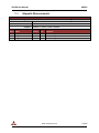
Magnetic Measurements ....................................................................... 59
7.19
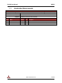
Acceleration Measurements .................................................................. 60
7.20
Angular Rate Measurements .................................................................. 61
7.21
Magnetic, Acceleration and Angular Rates ............................................ 62
7.22
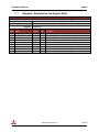
Magnetic and Gravity Reference Vectors ............................................... 63
7.23
Filter Measurements Variance Parameters ............................................ 64
7.24
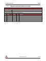
Magnetic Hard/Soft Iron Compensation Parameters ............................. 65
7.25
Filter Active Tuning Parameters ............................................................. 66
7.26
Accelerometer Compensation ................................................................ 67
7.27
Reference Frame Rotation ..................................................................... 68
7.28
Yaw, Pitch, Roll, Magnetic, Acceleration, and Angular Rates ................. 69
7.29
Accelerometer Gain ................................................................................ 70
www.vectornav.com
4/102
VN-100 User Manual
UM001
7.30
Yaw, Pitch, Roll, & Calibrated Measurements ........................................ 71
7.31
Communication Protocol Control ........................................................... 72
7.31.1
SerialCount .............................................................................................................. 72
7.31.2
SerialStatus ............................................................................................................. 73
7.31.3
SPICount .................................................................................................................. 73
7.31.4
SPIStatus ................................................................................................................. 73
7.31.5
SerialChecksum ....................................................................................................... 74
7.31.6
SPIChecksum ........................................................................................................... 74
7.31.7
ErrorMode ............................................................................................................... 74
7.31.8
Example Async Messages........................................................................................ 74
7.32
Communication Protocol Status ............................................................. 76
7.33
Synchronization Control ......................................................................... 77
7.33.1
SyncInMode ............................................................................................................ 77
7.33.2
SyncInEdge .............................................................................................................. 77
7.33.3
SyncInSkipFactor ..................................................................................................... 78
7.33.4
SyncOutMode ......................................................................................................... 78
7.33.5
SyncOutPolarity....................................................................................................... 78
7.33.6
SyncOutSkipFactor .................................................................................................. 78
7.33.7
SyncOutPulseWidth ................................................................................................ 79
7.34
Synchronization Status ........................................................................... 80
7.35
Filter Basic Control ................................................................................. 81
7.36
VPE Basic Control ................................................................................... 82
7.37
VPE Magnetometer Basic Tuning ........................................................... 83
7.38
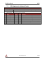
VPE Magnetometer Advanced Tuning.................................................... 84
7.39
VPE Accelerometer Basic Tuning ............................................................ 85
7.40
VPE Accelerometer Advanced Tuning .................................................... 86
7.41
VPE Gyro Basic Tuning ............................................................................ 87
7.42
Filter Status ............................................................................................ 88
7.43
Filter Startup Gyro Bias........................................................................... 89
7.44
Magnetometer Basic Calibration Control ............................................... 90
7.45
Magnetometer Calibration Status .......................................................... 91
www.vectornav.com
5/102
VN-100 User Manual
UM001
7.46
Calculated Magnetometer Calibration ................................................... 92
7.47
Indoor Heading Mode Control................................................................ 93
7.48
Yaw, Pitch, Roll, True Body Acceleration, and Angular Rates ................. 94
7.49
Yaw, Pitch, Roll, True Inertial Acceleration, and Angular Rates ............. 95
7.50
Yaw, Pitch, Roll, & Inertial Calibrated Measurements ............................ 96
7.51
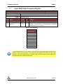
Raw Voltage Measurements .................................................................. 97
7.52
Calibrated IMU Measurements .............................................................. 98
7.53
Kalman Filter State Vector ...................................................................... 99
7.54
Kalman Filter Covariance Matrix Diagonal ........................................... 100
8 System Registers - Default Factory State ................................... 101
www.vectornav.com
6/102
VN-100 User Manual
1
UM001
Introduction
1.1
Product Description
The VN-100 is a miniature surface mount high performance Inertial Measurement Unit (IMU) and
Attitude Heading Reference System (AHRS). Incorporating the latest solid-state MEMS sensor
technology, the VN-100 combines 3-axis accelerometers, 3-axis gyros, and 3-axis magnetic sensors
as well as a 32-bit processor into a miniature surface mount module. Along with providing calibrated
sensor measurements the VN-100 also computes and outputs a real-time drift free 3D orientation
solution that is continuous over the complete 360 degrees of motion.
1.2
Product Features
The VN-100 is available in two different configurations, in a surface mounted package (VN-100 SMT), or
with an aluminum enclosure (VN-100 Rugged). The VN-100 Rugged provides a robust precision
anodized aluminum clamshell enclosure, ensuring precise alignment and calibration, while still retaining
the smallest possible footprint.
The VN-100 can be used as either an Inertial Measurement Unit (IMU) or as an orientation sensor
(AHRS). As an IMU the VN-100 relies on its high quality factory calibration. Each individual VN-100 is
calibrated to remove errors in 10 onboard sensors caused by scale factor, bias and misalignment. This
digital alignment also ensures that each of the three 3-axis inertial sensors share the same coordinate
frame, which is important for navigation applications.
For applications which require a full orientation solution, the VN-100 offers an onboard Aerospace grade
attitude estimation Kalman filter. This algorithm known as the Vector Processing Engine (VPE) provides
a drift-free 3D-orientatin solution that works in any orientation and is capable of handling both
acceleration and magnetic disturbances. For more information about the Vector Processing Engine see
Section 2.
www.vectornav.com
7/102
VN-100 User Manual
UM001
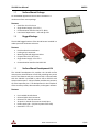
Surface Mount Package
1.3
For embedded applications the VN-100 is available in a
miniature surface mount package.
Features
Small Size: 24 x 22 x 3 mm
Single Power Supply: 3.2 to 5.5 V
Communication Interface: Serial TTL & SPI
Low Power Requirement: < 165 mW @ 3.3V
Rugged Package
1.4
The VN-100 Rugged consists of the VN-100 sensor installed in a
robust precision aluminum enclosure.
Features
Precision aluminum enclosure
Locking 10-pin connector
Mounting tabs with alignment holes
Compact Size: 33 x 26 x 9 mm
Single Power Supply: 4.5 to 5.5 V
Communication Interface: Serial RS-232
Surface Mount Development Kit
1.5
The VN-100 Development kit provides the VN-100 surface
mount sensor installed onto a small PCB, providing easy access
to all of the features and pins on the VN-100. Communication
with the VN-100 is provided by either USB or RS-232 serial
communication ports. A 20-pin header provides easy access to
all of the important pins. The development kit also includes all
of the necessary cables, documentation, and support software.
Features
Pre-installed VN-100 Sensor
Onboard USB->Serial converter
Onboard TTL->RS-232 converter
20-pin 0.1in header for access to VN-100 pins
Power supply jack – 5V (Can be power from USB)
Board Size: 2.9” x 2.9”
www.vectornav.com
8/102
VN-100 User Manual
UM001
VN-100 Rugged IMU/AHRS Development Kit
1.6
The VN-100 Rugged development kit includes the Rugged
sensor along with all of the necessary cables required for
operation. Two cables are provided in each development kit,
one for RS-232 communication, and a second custom cable
with a built in USB converter. The kit also includes all of the
relevant documentation and support software.
Features
1.6.1.1
1 VN-100 Rugged Sensor
1 10-foot RS-232 cable
1 6-foot USB connector cable
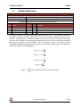
Sensor Coordinate System
The VN-100 uses a right-handed coordinate system. A positive yaw angle is defined as a positive righthanded rotation around the Z-axis. A positive pitch angle is defined as a positive right-handed rotation
around the Y-axis. A positive roll angle is defined as a positive right-handed rotation around the X-axis.
The axes direction with respect to the VN-100 module is shown in Figure 1.
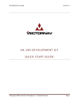
Figure 1 - VN-100 Coordinate System
www.vectornav.com
9/102
VN-100 User Manual
2
UM001
VN-100 Vector Processing Engine
2.1
Overview
Along with the 9-axis calibrated sensor array the VN-100 also incorporates onboard a 32-bit ARM
processor running VectorNav's general purpose attitude estimation algorithm known as the Vector
Processing Engine. The Vector Processing Engine (VPE) combines the measurements available from the
accelerometers, magnetometers and gyroscopes to derive a high accuracy 3D orientation solution with
minimal gyro drift for both static and dynamic conditions.
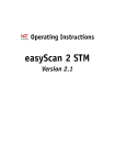
Vector Processing Engine
~
m
Adaptive
Filtering
Accelerometer
Factory Calibration
Adaptive
Tuning
a~
Adaptive
Filtering
Adaptive
Tuning
~ , mˆ
m
a~ , aˆ
a~ , aˆ
~
Gyroscope
Adaptive
Tuning
2.2
~ , mˆ
m
Extended Kalman Filter
HSI
Filter
Magnetometer
q̂
̂
~
Components of the VPE
The Vector Processing Engine (VPE) provides a complete embedded sensor fusion framework capable of
estimating the orientation and angular rate of an object in real-world environments where both
magnetic and acceleration disturbances are present. The VPE combines a collection of logic and filter
building blocks into a single software package, minimizing the additional processing necessary by the
end user to obtain an accurate attitude estimate. The overall operation of the VPE can be divided into 5
distinct stages.
1.
2.
3.
4.
5.
Static (Factory) Calibration
Dynamic Calibration
Adaptive Filtering
Adaptive Tuning
Attitude Estimation
www.vectornav.com
10/102
VN-100 User Manual
2.3
UM001
Static (Factory) Calibration
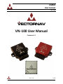
During the static calibration stage each of the ten sensors (3-axis magnetometer, 3-axis accelerometer,
3-axis gyro, and temperature sensor) are digitally compensated to eliminate the errors due to scale
factor, axis-misalignment, biases, and temperature sensitivity. For the gyros, sensitivity to acceleration is
also taken into account. Each VectorNav sensor is individually calibrated in temperature-controlled
robotic calibration stands at our factory to determine each sensor’s unique calibration coefficients. Each
sensor is subjected to precisely known rotations and orientations across the specified performance
temperature range. The data collected from these tests is used at the factory to calculate the unique
calibration coefficients for each individual sensor, and these calibration coefficients are permanently
stored in flash. During operation at each time step after the raw measurements are collected from the
sensors, the calibration coefficients are digitally applied to compensate for the known systematic errors
measured during the factory calibration. This static calibration is automatically applied at each time
step by the VN-100 and no additional processing is required by the end user.
Figure 2 - Sensor Calibration
+Bias
Y-Axis
+-
x
Scale Factor
+-
Z-Axis
Bias
X-Axis
Scale Factor
Bias
2.4
x
x
Misalignment
X-Axis
Y-Axis
Z-Axis
Scale Factor
Dynamic (Real-time) Calibration
Some of the sensors have calibration parameters that are time-variant, or are altered when the sensor is
installed into its intended application. The magnetometer for example experiences changes to its
apparent scale and bias due to the effect of nearby ferrous materials which alter the measured local
magnetic field. If not properly accounted for these distortions can result in a significant loss of heading
accuracy. Traditionally hard/soft iron distortions are accounted for using off-line post-processing
techniques. The VPE utilizes a separate optional Kalman Filter running in the background to estimate
on-line the hard/soft iron distortions. This eliminates the need for off-line data processing and allows
the VPE to dynamically adapt to potentially varying magnetic conditions. More information about the
operation of the automatic hard/soft iron calibration can be found in Section 2.17. The VPE utilizes the
main attitude estimation filter to calculate the time varying gyro bias at each time step. By dynamically
removing this gyro bias the VPE is able to provide a drift-free orientation and angular rate estimate. The
gyro bias is calculated at all times, even during periods of motion, and does not rely on the device to be
placed in a stationary state for periodic “zeroing” of the bias.
www.vectornav.com
11/102
VN-100 User Manual
2.5
UM001
Adaptive Filtering
The VPE employs adaptive filtering techniques to significantly reduce the effect of high frequency
disturbances in both magnetic and acceleration. Prior to entering the attitude filter, the magnetic and
acceleration measurements are digitally filtered to reduce high frequency components typically caused
by electromagnetic interference and vibration. The level of filtering applied to the inputs is dynamically
altered by the VPE in real-time. The VPE calculates the minimal amount of digital filtering required in
order to achieve specified orientation accuracy and stability requirements. By applying only the minimal
amount of filtering necessary, the VPE reduces the amount of delay added to the input signals. For
applications that have very strict latency requirements, the VPE provides the ability to limit the amount
of adaptive filtering performed on each of the input signals. For more information on how to adjust the
level of adaptive filtering see Section 2.16.
2.6
Adaptive Tuning
Kalman filters employ coefficients that specify the uncertainty in the input measurements which are
typically used as “tuning parameters” to adjust the behavior of the filter. Normally these tuning
parameters have to be adjusted by the engineer to provide adequate performance for a given
application. This tuning process can be ad-hoc, time consuming, and application dependent. The VPE
employs adaptive tuning logic which provides on-line estimation of the uncertainty of each of the input
signals during operation. This uncertainty is then applied directly to the onboard attitude estimation
Kalman filter to correctly account for the uncertainty of the inputs. The adaptive tuning reduces the
need for manual filter tuning. For more information on how to adjust the level of adaptive tuning
performed by the VPE see Section 2.15.
2.7
Attitude Estimation
The orientation and angular rate are calculated using a quaternion based Extended Kalman Filter. The
estimation algorithm employs quaternion math to eliminate the problem of gimbal lock, allowing the
device to provide consistent and stable output in any orientation. Along with estimating the orientation,
the filter also estimates the time-varying gyro bias. This provides a drift-free orientation and angular
rate estimate even during periods of sustained motion. The attitude is estimated using the vector
measurements from both the magnetometer and accelerometers. The magnetometers can be used in
either 2D or 3D mode. In 2D mode, the magnetometer will only affect the estimated heading, and the
pitch and roll will only be determined by the output of the accelerometer. In 3D mode the
magnetometer input is allowed to affect the full attitude solution. For applications where the magnetic
field is well defined and free of any un-modeled disturbances, operating in 3D mode will in theory
provide the highest level of orientation accuracy. For most applications however, operating with the
magnetometer in 2D mode provides the best overall accuracy due to the inherent uncertainty and
variability in the local magnetic field. For more information on the settings pertaining to the Attitude
Estimation algorithm see Section 7.35.
2.8
VPE Magnetic Heading Modes
The VectorNav VPU provides three separate heading modes. Each mode controls how the VPE
interprets the magnetic measurements to estimate the heading angle. The three modes are described
in detail in the following sections.
www.vectornav.com
12/102
VN-100 User Manual
UM001
Absolute Heading Mode
2.9
In Absolute Heading Mode the VPE will assume that the principal long-term DC component of the
measured magnetic field is directly related to the earth’s magnetic field. As such only short term
magnetic disturbances will be tuned out. This mode is ideal for applications that are free from low
frequency (less than ~ 1Hz) magnetic disturbances and/or require tracking of an absolute heading. Since
this mode assumes that the Earth's magnetic field is the only long-term magnetic field present, it cannot
handle constant long-term magnetic disturbances which are of the same order of magnitude as the
Earth's magnetic field and cannot be compensated for by performing a hard/soft iron calibration. From
the sensor's perspective a constant long-term magnetic disturbance will be indistinguishable from the
contribution due to the Earth's magnetic field, and as such if present it will inevitably result in a loss of
heading accuracy.
If a magnetic disturbance occurs due to an event controlled by the user, such as the switching
on/off of an electric motor, an absolute heading can still be maintained if the device is notified
of the presence of the disturbance. For more information see the Known Magnetic
Disturbance Command (Section 6.4.7.)
To correctly track an absolute heading you will need to ensure that the hard/soft iron
distortions remains well characterized. See Section 2.17 for more information on hard/soft
iron distortions and the automated calibration module.
Absolute Heading Mode Advantages
Provides short-term magnetic disturbance rejection while maintaining absolute tracking of the
heading relative to the fixed Earth.
Absolute Heading Mode Disadvantages
If the magnetic field changes direction relative to the fixed Earth, then its direction will need to
be updated using the reference vector register in order to maintain an accurate heading
reference.
Hard/Soft iron distortions that are not properly accounted for will induce heading errors
proportional to the magnitude of the hard/soft iron distortion. In some cases this could be as
high as 30 - 40 degrees.
2.10
Relative Heading Mode
In Relative Heading mode the VPE makes no assumptions as to the long term stability of the magnetic
field present. In this mode the VPE will attempt to extract what information it reasonably can from the
magnetic measurements in order to maintain an accurate estimate of the gyro bias. The VPE will
constantly monitor the stability of the magnetic field and when it sees that its direction is reasonably
stable, the VPE will maintain a stable heading estimate. Over long periods of time under conditions
where the magnetic field direction changes frequently, in Relative Heading mode it is possible for the
VN-100 to accumulate some error in its reported heading relative to true North. In this mode the VPE
will not attempt to correct for this accumulated heading error.
Relative Heading mode does not assume that the Earth's magnetic field is the only long-term magnetic
field present. As such this mode is capable of handling a much wider range of magnetic field
disturbances while still maintaining a stable attitude solution. Relative Heading mode should be used in
www.vectornav.com
13/102
VN-100 User Manual
UM001
situations where the most important requirement is for the attitude sensor is to maintain a stable
attitude solution which minimizes the effect of gyro drift while maintaining a stable and accurate pitch
and roll solution. Since the Relative Heading mode assumes that other magnetic disturbances can be
present which are indistinguishable from the Earth's field, Relative Heading mode cannot always ensure
that the calculated heading is always referenced to Earth's magnetic north.
Use the Relative Heading mode for applications where the stability of the estimated heading
is more important than the long-term accuracy relative to true magnetic North. In general,
the Relative Heading mode provides better magnetic disturbance rejection that the Absolute
Heading mode.
Relative Heading Mode Advantages
Capable of handling short-term and long-term magnetic interference
Can handle significant errors in the hard/soft iron while still maintaining a stable heading and
gyro bias estimate.
Relative Heading Mode Disadvantages
Unable to maintain heading estimate relative to true North in environments with frequent longterm magnetic field disturbances.
2.11
Indoor Heading Mode
The Indoor Heading mode was designed to meet the needs of applications that require the enhanced
magnetic disturbance rejection capability of the Relative Heading mode, yet desire to maintain an
absolute heading reference over long periods of time. The Indoor Heading mode extends upon the
capabilities of the Relative Heading mode by making certain assumptions as to the origin of the
measured magnetic fields consistent with typical indoor environments.
In any environment the measured magnetic field in 3D space is actually the combination of the Earth’s
magnetic field plus the contribution of other local magnetic fields created by nearby objects containing
ferromagnetic materials. For indoor environments this becomes problematic due to the potential close
proximity to objects such as metal desk, chairs, speakers, rebar in the concrete floor, and other items
which either distort or produce their own magnetic field. The strength of these local magnetic fields are
position dependent, and if the strength is on the same order of magnitude as that of the Earth’s
magnetic field, directly trusting the magnetic measurements to determine heading can lead to
inaccurate heading estimates.
While in Indoor Heading mode the VPE inspects the magnetic measurements over long periods of time,
performing several different tests on each measurement to quantify the likelihood that the measured
field is free of the influence of any position dependent local magnetic fields which would distort the
magnetic field direction. Using this probability the VPE then estimates the most likely direction of the
Earth’s magnetic field and uses this information to correct for the heading error while the device is in
motion.
For the Indoor Heading mode you can adjust how quickly the VPE compensates for known
errors in heading. For more information see the Indoor Mode Control register (Section 7.47.)
www.vectornav.com
14/102
VN-100 User Manual
UM001
Indoor Heading Mode Advantages
Capable of handling short-term and long-term magnetic interference
Can handle significant errors in the hard/soft iron while still maintaining a stable heading and
gyro bias estimate.
Capable of maintaining an accurate absolute heading over extended periods of time.
Indoor Heading Mode Disadvantages
Measurement repeatability may be slightly worse than Relative Mode during periods when the
VPE corrects for known errors in absolute heading.
2.12
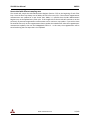
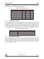
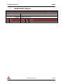
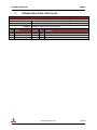
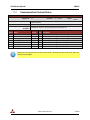
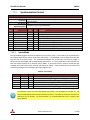
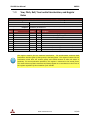
Overview of Heading Modes
A summary of the different types of disturbances handled by each magnetic mode is summarized in the
table below.
Table 1 - Types of Disturbances handled by each Magnetic Mode
Capabilities
Handle high frequency magnetic disturbances
greater than 1Hz?
Handle constant disturbances lasting less than a
few seconds?
Handle constant disturbances lasting longer
than a few seconds?
Maintain accurate heading relative to true
North over long periods of time?
Absolute Heading
Relative Heading
Indoor Mode
Yes
Yes
Yes
Yes
Yes
Yes
No
Yes
Yes
Yes
No
Yes*
* Accuracy depends upon recovery rate settings. See Section 7.47 for more information.
2.13
VPE Adaptive Filtering and Tuning Settings
The VPE actively employs both adaptive filtering and adaptive tuning techniques to enhance
performance in conditions of dynamic motion and magnetic and acceleration disturbances. The VPE
provides the ability to modify the amount of adaptive filtering and tuning applied on both the
magnetometer and the accelerometer. In many cases the VPE can be used as is without any need to
adjust these settings. For some applications higher performance can be obtained by adjusting the
amount of adaptive filtering and tuning performed on the inputs. For both the magnetometer and the
accelerometer the following settings are provided.
2.14
Static Measurement Uncertainty
The static gain adjusts the level of uncertainty associated with either the magnetic or acceleration
measurement when no disturbances are present. The level of uncertainty associated with the
measurement will directly influence the accuracy of the estimated attitude solution. The level of
uncertainty in the measurement will also determine how quickly the attitude filter will correct for errors
in the attitude when they are observed. The lower the uncertainty, the quicker it will correct for
observed errors.
This parameter can be adjusted from 0 to 10.
Zero places no confidence (or infinite uncertainty) in the sensor, thus eliminating its effect on
the attitude solution.
www.vectornav.com
15/102
VN-100 User Manual
UM001
Ten places full confidence (minimal uncertainty) in the sensor and assume that its
measurements are always 100% correct.
2.15
Adaptive Tuning Gain
The adaptive tuning stage of the VPE monitors both the magnetic and acceleration measurements over
an extended period of time to estimate the time-varying level of uncertainty in the measurement. The
adaptive tuning gain directly scales either up or down this calculated uncertainty.
This parameter can be adjusted from 0 to 10.
The minimum value of zero turns off all adaptive tuning.
The maximum value of 10 applies several times the estimated level of uncertainty.
2.16
Adaptive Filtering Gain
The adaptive filtering stage of the VPE monitors both the magnetic and acceleration measurements to
determine if large amplitude high frequency disturbances are present. If so then a variable level of
filtering is applied to the inputs in order to reduce the amplitude of the disturbance down to acceptable
levels prior to inputting the measurement into the attitude filter. The advantage of the adaptive
filtering is that it can improve accuracy and eliminate jitter in the output attitude when large amplitude
AC disturbances are present. The disadvantage to filtering is that it will inherently add some delay to the
input measurement. The adaptive filtering gain adjusts the maximum allowed AC disturbance amplitude
for the measurement prior to entering the attitude filter. The larger the allowed disturbance, the less
filtering that will be applied. The smaller the allowed disturbance, the more filtering will be applied.
This parameter can be adjusted from 0 to 10.
The minimum value of zero turns off all adaptive filtering.
The maximum value of 10 will apply maximum filtering.
Keep in mind that regardless of this setting, the adaptive filtering stage will apply only the minimal
amount of filtering necessary to get the job done. As such this parameter provides you with the ability
to set the maximum amount of delay that you are willing to accept in the input measurement.
2.17
Magnetic Hard/Soft Iron Calibration
Hard and soft iron distortions are caused by ferromagnetic materials that are close to and rigidly
attached to the same object as the sensor. Hard iron distortions create an additive magnetic field and
add directly to the measured Earth’s magnetic field. Hard iron objects include anything that is either
magnetic or has been magnetized. Soft iron distortion comes from objects made from materials such as
iron, cobalt, and nickel which distort the direction of an existing magnetic field. Because their effect on
the field is a function of their direction relative to the Earth’s magnetic field, compensating for both hard
and soft iron distortions isn’t trivial and requires collecting data while the sensor is rotated in many
different orientations.
The VPE utilizes a separate Kalman filter running in the background to perform real-time compensation
for hard and soft iron disturbances. The hard and soft iron calibration can either be run once and the
parameters saved to flash memory for future use, or the calibration can be left running in the
background to continuously compensate for possible changes in the hard and soft iron distortions.
www.vectornav.com
16/102
VN-100 User Manual
UM001
As an embedded sensor in many applications the VN-100 may be mounted in close proximity
to removable battery packs. Batteries contain many metals that have both hard and soft iron
characteristics. For these applications it may be desirable to leave the hard/soft iron
calibration running in the background so that if a battery pack is swapped the sensor will
dynamically adjust to any variations in hard/soft iron characteristics different between the
battery packs.
For more information on how to turn on/off the hard/soft iron calibration and adjust its settings see the
Magnetic Calibration Control Register (Section 7.44.)
www.vectornav.com
17/102
VN-100 User Manual
3
UM001
Operation and Usage Scenarios
The following section provides an overview as to the various ways the VN-100 sensor can be used. It
describes in detail how the VN-100 can be used as an IMU or an orientation sensor, various
synchronization options, and installation and alignment procedures. This section should serve as a
preliminary guide that will get you up and running with the VN-100. For more implementation specific
details, see our application notes section on the website.
3.1
Using the VN-100 as an Inertial Measurement Unit
As an Inertial Measurement Unit (IMU), the VN-100 is utilized to provide only calibrated acceleration,
angular rates, and magnetic field measurements. Typically when the device is used as an IMU, the
attitude information isn't required. The VN-100 will always compute the attitude solution onboard
regardless of whether it is being used or not.
The VN-100 offers a SyncOut line that can be software configured to trigger either when the IMU or the
attitude measurements are available. The device defaults to trigger when the attitude information is
available. To reduce the measurement latency when the device is solely used as an IMU, it is
recommended that the SyncOut line is switched to trigger when new IMU measurements are available.
The VN-100 provides two different angular rate measurements.
The un-compensated rate
measurements (available in Register 252) come straight from the calibrated gyro and are not altered by
the onboard running Kalman filter. The compensated rate measurements (available in Register 20) are
corrected for the gyro bias drift by the onboard Kalman filter. When the Kalman filter is properly tuned
the compensated rates are drift-free. Normally however, for an IMU uncompensated angular rates are
preferred since gyro bias estimation is usually handled by a higher level filter.
Setting up the VN-100 as an IMU
To use the VN-100 as an IMU, from the factory default state performs the following steps.
1. Set the SyncOut to trigger when the IMU data is available. For more information on this register see
Section 7.33.
Interface
Serial
SPI
Write Register - Set SyncOut to IMU Mode
$VNWRG,32,0,0,0,0,2,0,0,500000,0*5C
02 20 00 00 00 00 00 00 00 00 00 00 02 00 00 00 00 07 A1 20 00 00 00 00
2. Read the IMU data using Register 252 (Section 7.52). This register provides the calibrated
magnetometer, accelerometer, and un-compensated angular rate measurements.
Interface
Serial
SPI
Read Register - IMU Data
$VNRRG,252*46
01 FC 00 00
For information on how to parse the response to this read register command see Section 7.52.
www.vectornav.com
18/102
VN-100 User Manual
3.2
UM001
Using the VN-100 as an Orientation Sensor
The VN-100 can be used as either an Inertial Measurement Unit, and orientation sensor, or both. After
capturing new IMU measurements, the VN-100 immediately begins computing a new attitude solution
(orientation) using its onboard Kalman filter. The attitude is provided either as Euler angles, a
quaternion, or a directional cosine matrix. Below are the registers that are commonly used when the
VN-100 is used as an orientation sensor.
Register
8
9
16
27
15
Register Name
Yaw, Pitch, Roll
Quaternion
Directional Cosine Matrix
Yaw, Pitch, Roll, and IMU Data
Quaternion and IMU Data
ADOR ID
1
2
9
14
8
ADOR Name
YPR
QTN
DCM
YMR
QMR
The VN-100 offers a SyncOut line that can be software configured to trigger either when the IMU or the
attitude measurements are available. The device defaults to trigger when the attitude information is
available.
When using the device as an orientation sensor it is important that the attitude filter is set to
the correct operational mode. For more information on which operational mode is best suited
for your application see Section 2.8.
Set the Filter Operational Mode
The filter operational mode is selected in the Filter Control Register (Section 7.35).
3.3
Synchronizing the VN-100 with other devices
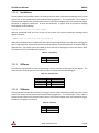
3.4
Synchronizing Multiple VN-100's
The synchronization feature can be used to synchronize multiple VN-100 sensors together such that all
sensors sample at the same time. To do this, select one sensor to be the master. The remaining sensors
in the network will be considered slaves. Connect the SyncOut line of the master to the SyncIn lines of
each of the slaves.
Figure 3 - Synchronizing Multiple VN-100's
www.vectornav.com
19/102
VN-100 User Manual
UM001
Using the Synchronization Control Register (Section 7.33), the master unit needs to be set to output a
pulse on the SyncOut pin when the ADC sampling begins. To do this send the following command to the
master device.
Interface
Serial
SPI
Write Register - Set Master SyncOut
$VNWRG,32,0,0,0,0,1,0,0,500000,0*5F
02 20 00 00 00 00 00 00 00 00 00 00 01 00 00 00 00 07 A1 20 00 00 00 00
On each slave unit the SyncIn line must be configured to trigger on the ADC sampling. To do this send
the following command to the slave devices.
Interface
Serial
SPI
3.5
Write Register - Set Slave SyncIn
$VNWRG,32,1,0,0,0,3,0,0,500000,0*5C
02 20 00 00 01 00 00 00 00 00 00 00 03 00 00 00 00 07 A1 20 00 00 00 00
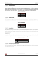
Running the VN-100 off an external clock
It is also possible to use an external clock to drive the ADC sampling and filter loop of the VN-100.
Normally the VN-100 uses its internal clock to run the internal filtering loop which is fixed at 200Hz. An
external signal can be used in place of the internal clock provided that the VN-100 can still be run at
precisely 200Hz. It is important to note that the VN-100 filter loop must run at precisely 200Hz at all
times. During the integration step of the onboard filtering a fixed time step of 5ms is always assumed.
If a signal other than 200Hz is used to run the filter, then you will have significant performance
degradation due to incorrect propagation of the gyro rates. It is possible to run the VN-100 filter loop at
200Hz using a higher frequency signal, provided that the signal frequency is a multiple of the required
200Hz. For example a 1kHz signal can be used by setting the SyncInSkipFactor in the Synchronization
Control Register (Section 7.33) equal to 4. With this setting the device will trigger on every 5th edge
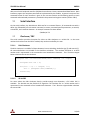
selected by the SyncInEdge field.
Figure 4 - Using an external clock
To set the VN-100 to operate using an external clock, send the following command to the device.
Interface
Serial
SPI
Write Register - Set to Use External Clock
$VNWRG,32,1,0,0,0,1,0,0,500000,0*5E
02 20 00 00 01 00 00 00 00 00 00 00 01 00 00 00 00 07 A1 20 00 00 00 00
www.vectornav.com
20/102
VN-100 User Manual
UM001
Using the VN-100 with external sensors
3.6
Normally the VN-100 uses the onboard gyroscopes, accelerometer, and magnetometer to compute its
attitude solution. For some applications it is desirable to use a separate accelerometer or
magnetometer with the VN-100. For example on Unmanned Aerial Vehicles (UAVs) the IMU is typically
located close to the center of gravity while the magnetometer is located further away from the
electronics, such as out on the end of the wing. This can be accomplished by setting the ExtMagMode
field in the Filter Control Register (Section 7.35).
Set the VN-100 to use an External Magnetometer
Send the following command to the VN-100 to instruct it to use an external magnetometer.
Interface
Serial
SPI
Write Register - Use External Magnetometer
$VNWRG,34,2,0,1,0*72
02 22 00 00 02 00 01 00
Set the VN-100 to use an External Accelerometer
Send the following command to the VN-100 to instruct it to use an external accelerometer.
Interface
Serial
SPI
Write Register - Use External Magnetometer
$VNWRG,34,0,2,1,0*72
02 22 00 00 00 02 01 00
In the Filter Control Register (Section 7.35) the ExtMagMode and the ExtAccMode fields allow you to set
which type of magnetometer and accelerometer respectfully are used by the onboard attitude filter.
How to update the External Magnetometer Measurements
In order to update the external magnetometer measurements you will need to write to the Calibrated
IMU Measurements Register (Section 7.52). This register normally is read-only, however when either
the ExtMagMode or the ExtAccMode is set to use an external sensor then writing to this register will
replace the corresponding internal sensor measurements with the ones provided. All fields other than
the ones corresponding to the external sensor will remain read-only and will their values will remain
unaffected by the write register command. For these other values you can provide a zero value. Below
shows an example of how to update the external magnetometer at each time step.
Figure 5 - Provide the VN-100 with External Magnetometer Measurements
Interface
Serial
SPI
Write Register - Write External Magnetometer Measurement
$VNWRG,252,1.0,-0.1,1.8,0,0,0,0,0,0,0*79
02 FC 00 00 00 00 80 3F CD CC CC BD 66 66 E6 3F 00 00 00 00 00 00 00 00 00
00 00 00 00 00 00 00 00 00 00 00 00 00 00 00 00 00 00 00
Figure 6 - Provide the VN-100 with External Accelerometer Measurements
Interface
Serial
SPI
Write Register - Write External Magnetometer Measurement
$VNWRG,252,0,0,0,0.1,1.5,-9.81,0,0,0,0*79
02 FC 00 00 00 00 00 00 00 00 00 00 00 00 00 00 CD CC CC 3D 00 00 C0 3F C3
F5 1C C1 00 00 00 00 00 00 00 00 00 00 00 00 00 00 00 00
www.vectornav.com
21/102
VN-100 User Manual
UM001
How to deal with different sampling rates
The VN-100 will sample the IMU Measurement Register (Section 7.52) at the beginning of each filter
loop. Since the filter loop always runs at 200Hz, this will occur every 5ms. If the external magnetometer
measurements are updated at a rate slower than 200Hz, it is possible that the IMU Measurement
Register may not be updated every filter cycle. If this happens then the VN-100 will continue to use the
previously set external magnetometer measurement until it receives a new update. If you wish to have
the attitude filter only use the magnetometer data to update the attitude filter when the magnetometer
measurement updates, then set the ExtMagMode field to 2. In this state, the magnetometer will be
tuned out during the time steps that it isn't updated.
www.vectornav.com
22/102
VN-100 User Manual
4
UM001
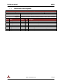
Specifications
4.1
4.1.1
Pin-out and Electrical Specifications
VN-100 Surface Mount Sensor (SMT)
Figure 7 – Pin assignments (top down view)
www.vectornav.com
23/102
VN-100 User Manual
UM001
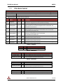
Table 2 – VN-100 SMT Pin Assignments
Pin #
1
2
3
4
5
6
Pin Name
GND
GND
GND
GND
TX2
RX2
7
TARE/RESTORE
8
9
10
NC
SYNC_OUT
VIN
11
ENABLE
12
13
14
TX1
RX1
RESV
15
SYNC_IN_2
16
17
18
19
SPI_SCK
SPI_MOSI
GND
SPI_MISO
20
REPRGM
21
NRST
22
23
24
25
26
27
28
29
30
SYNC_IN
SPI_CS
RESV
RESV
RESV
RESV
GND
RESV
GND
Description
Ground.
Ground.
Ground.
Ground.
Serial UART #2 data output. (sensor)
Serial UART #2 data input. (sensor)
Normally used to zero (tare) the attitude.
To tare, pulse high for at least 1 μs. During power on or device reset, holdin
g this pin high will cause the module to restore its default factory settings.
Because of this, the pin cannot be used for tare until at least 5 ms after a
power on or reset. Internally held low with 10k resistor.
Not used.
Time synchronization output signal. See section 7.33 for more details.
3.2 - 5.5V input.
Leave high for normal operation. Pull low to enter sleep mode. Internally
pulled high with pull-up resistor.
Serial UART #1 data output. (sensor)
Serial UART #1 data input. (sensor)
Reserved for future use. Leave pin floating.
Reserved for future use. For backwards compatibility with older hardware
revisions this pin can be configured in software to operate as the time
synchronization input signal. For new designs it is recommended that
SYNC_IN (pin 22) is used instead. See Section 7.33 for more details.
SPI clock.
SPI input.
Ground.
SPI output.
Used to reprogram the module. Must be left floating or set to low for
normal operation. Pull high on startup to set the chip in reprogram mode.
Internally held low with 10k resistor.
Microcontroller reset line. Pull low for > 20μs to reset MCU. Internally
pulled high with 10k.
Time synchronization input signal. See Section 7.33 for more details.
SPI slave select.
Reserved for future use. Leave pin floating.
Reserved for future use. Leave pin floating.
Reserved for future use. Leave pin floating.
Reserved for future use. Leave pin floating.
Ground.
Reserved for future use. Leave pin floating.
Ground.
www.vectornav.com
24/102
VN-100 User Manual
4.1.1.1
UM001
VN-100 SMT Power Supply
The minimum operating supply voltage is 3.2V and the absolute maximum is 5.5V.
4.1.1.2
VN-100 SMT Serial (UART) Interface
The serial interface on the VN-100 operates with 3V TTL logic.
Table 3 - Serial I/O Specifications
Specification
Input low level voltage
Input high level voltage
Output low voltage
Output high voltage
4.1.1.3
Min
-0.5V
2V
0V
2.4V
Typical
Max
0.8V
5.5V
0.4V
3.0V
VN-100 SMT Serial Peripheral Interface (SPI)
Table 4 - Serial I/O Specifications
Specification
Input low level voltage
Input high level voltage
Output low voltage
Output high voltage
Clock Frequency
Close Rise/Fall Time
4.1.1.4
Min
-0.5V
2V
0V
2.4V
Typical
8 MHz
Max
0.8V
5.5V
0.4V
3.0V
16 MHz
8 ns
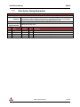
VN-100 SMT Reset, SyncIn/Out, and Other General I/O Pins
Table 5 - NRST Specifications
Specification
Input low level voltage
Input high level voltage
Weak pull-up equivalent resistor
NRST pulse width
Min
-0.5V
2V
30 kΩ
20 μs
Typical
40 kΩ
Max
0.8V
5.5V
50 kΩ
Table 6 - SyncIn Specifications
Specification
Input low level voltage
Input high level voltage
Input Frequency
Pulse Width
Min
-0.5V
2V
200 Hz
500 μs
Typical
200 Hz
Max
0.8V
5.5V
1 kHz
Table 7 - SyncOut Specifications
Specification
Output low voltage
Output high voltage
Output high to low fall time
Output low to high rise time
Output Frequency
Min
0V
2.4V
1 Hz
www.vectornav.com
Typical
Max
0.4V
3.0V
125 ns
125 ns
200 Hz
25/102
VN-100 User Manual
4.1.2
UM001
VN-100 Rugged
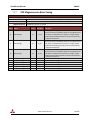
Table 8 – VN-100 Rugged Pin Assignments
Pin #
1
2
3
Pin Name
VCC
TX1
RX1
4
SYNC_OUT
5
GND
6
TARE/RESTORE
7
SYNC_IN
8
9
10
TX2_TTL
RX2_TTL
RESV
Description
+5V (±0.5V)
RS-232 voltage levels data output from the sensor. (Serial UART #1)
RS-232 voltage levels data input to the sensor. (Serial UART #1)
Output signal used for synchronization purposes. Software configurable
to pulse when ADC, IMU, or attitude measurements are available.
Ground
Input signal used to zero the attitude of the sensor. If high at reset, the
device will restore to factory default state. Internally held low with 10k
resistor.
Input signal for synchronization purposes. Software configurable to
either synchronize the measurements or the output with an external
device.
Serial UART #2 data output from the device at TTL voltage level (3V).
Serial UART #2 data into the device at TTL voltage level (3V).
This pin should be left unconnected.
Figure 8 - VN-100 Rugged External Connector
www.vectornav.com
26/102
VN-100 User Manual
4.1.2.1
UM001
VN-100 Rugged Power Supply
The nominal power supply for the VN-100 Rugged is 5V DC.
4.1.2.2
The VN-100 Rugged internally has overvoltage protection set at a fixed voltage of 5.8V. Upon an
overvoltage event the protection circuitry will disable power to the VN-100 to reduce possibility
of damage to the voltage regulator onboard the VN-100.
VN-100 Rugged Serial UART Interface
Table 9 - Serial I/O Specifications
Specification
Input low level voltage
Input high level voltage
Output low voltage
Output high voltage
Output resistance
Data rate
Pulse slew
4.1.2.3
Min
-25V
Typical
-5.0V
5.0V
300 Ω
-5.4V
5.5V
10 MΩ
Max
25V
1 Mbps
300 ns
VN-100 Rugged Reset, SyncIn/Out, and Other General I/O Pins
Table 10 - NRST Specifications
Specification
Input low level voltage
Input high level voltage
Weak pull-up equivalent resistor
NRST pulse width
Min
-0.5V
2V
30 kΩ
20 μs
Typical
40 kΩ
Max
0.8V
5.5V
50 kΩ
Table 11 - SyncIn Specifications
Specification
Input low level voltage
Input high level voltage
Input Frequency
Pulse Width
Min
-0.5V
2V
200 Hz
500 μs
Typical
200 Hz
Max
0.8V
5.5V
1 kHz
Table 12 - SyncOut Specifications
Specification
Output low voltage
Output high voltage
Output high to low fall time
Output low to high rise time
Output Frequency
Min
0V
2.4V
1 Hz
www.vectornav.com
Typical
Max
0.4V
3.0V
125 ns
125 ns
200 Hz
27/102
VN-100 User Manual
4.2
UM001
Physical Specifications and Dimensions
4.2.1
VN-100 Surface Mount Sensor
4.2.1.1
Footprint
Figure 9 – VN-100 PCB Footprint
* Measurements are in inches
4.3
Absolute Maximum Ratings
Table 13 - Absolute Maximum Ratings
Specification
Input Voltage
Operating Temperature
Storage Temperature
5
Min
-0.3V
-40 C
-40 C
Max
5.5V
85 C
85 C
Basic Communication
The VN-100 module supports two communication interfaces: serial and SPI. On the serial interface, the
module communicates over a universal asynchronous receiver/transmitter (UART) and uses ASCII text
for its command and data format. On the SPI interface, the VN-100 module communicates as a slave
www.vectornav.com
28/102
VN-100 User Manual
UM001
device on a Serial Peripheral Interface (SPI) data bus and uses a binary command and data format. Both
interfaces support the complete command set implemented by the module. A general overview of the
command format for each interface is given in the next two sections and formatting specific to each
command and associated parameters is provided in the protocol and register sections (Section 5 & 6).
Serial Interface
5.1
On the serial interface, the VN-100 uses ASCII text for its command format. All commands start with a
dollar sign, followed by a five character command, a comma, command specific parameters, an asterisk,
a checksum, and a newline character. An example command is shown below.
$VNRRG,11*73
Checksum / CRC
5.2
The serial interface provides the option for either an 8-bit checksum or a 16-bit CRC. In the event
neither the checksum nor the CRC is needed, they can be turned off by the user.
5.2.1.1
8-bit Checksum
The 8-bit checksum is an XOR of all bytes between, but not including, the dollar sign ($) and asterisk (*).
All comma delimiters are included in the checksum calculation. The resultant checksum is an 8-bit
number and is represented in the command as two hexadecimal characters. The C function snippet
below calculates the correct checksum.
unsigned char calculateChecksum(char* command, int length)
{
unsigned char xor = 0;
for(int i = 0; i < length; i++)
xor ^= (unsigned char)command[i];
return xor;
}
5.2.1.2
16-bit CRC
For cases where the 8-bit checksum doesn't provide enough error detection, a full 16-bit CRC is
available. The VN-100 uses the CRC16-CCITT algorithm. The resultant CRC is a 16-bit number and is
represented in the command as four hexadecimal characters. The C function snippet below calculates
the correct CRC.
www.vectornav.com
29/102
VN-100 User Manual
UM001
unsigned short calculateChecksum(char* command, int length)
{
unsigned int i;
unsigned short crc = 0;
for(i=0; i<length; i++){
crc = (unsigned char)(crc >> 8) | (crc << 8);
crc ^= command[i];
crc ^= (u8)(crc & 0xff) >> 4;
crc ^= (crc << 8) << 4;
crc ^= ((crc & 0xff) << 4) << 1;
}
return crc;
}
5.3
SPI Interface
The SPI interface uses a lightweight binary message format. The start of a command is signaled by
pulling the VN-100 module’s chip select pin (pin 23) low. Both the chip select line and clock are active
low. The first byte transmitted to the module should be the command ID and then a variable number of
bytes will follow dependent on the type of command specified. A communication transaction can be
cancelled at any time by releasing the chip select pin. Pulling the pin low again will start a new
communication transaction. All binary data is sent to and from the chip with most significant bit (MSB)
first in little-endian byte order with pad bytes inserted where required to ensure 16-bit values are
aligned to two-byte boundaries and 32-bit values are aligned to 4-byte boundaries. For example the
serial baud rate register with a value of 9600 (0x2580) would be sent across the SPI as a 0x80, 0x25,
0x00, 0x00. Data is requested from and written to the device using multiple SPI transactions.
Figure 10 – SPI Timing Diagram
www.vectornav.com
30/102
VN-100 User Manual
UM001
Figure 11 - SPI Data Diagram
A response for a given SPI command will be sent over the MISO line on the next SPI transaction. Thus
the data received by the Master on the MISO line will always be the response to the previous
transaction. So for example if Yaw, Pitch, Roll and angular rates are desired, then the necessary SPI
transactions would proceed as shown below.
SPI Transaction 1
Line
SCK
MOSI
MISO
Bytes
8 bytes
Description
01 08 00 00 00 00 00 00 (shown as hex)
00 00 00 00 00 00 00 00 (shown as hex)
Read register 8 (Yaw, Pitch, Roll)
No response
Line
SCK
Bytes
16 bytes
SPI Transaction 2
Description
MISO
01 13 00 00 00 00 00 00 00 00 00 00 00 00 00 00
(shown as hex)
00 01 08 00 39 8A 02 43 FD 43 97 C1 CD 9D 67 42
(shown as hex)
Line
SCK
Bytes
16 bytes
MOSI
Read register 13 (Angular Rates)
Yaw, Pitch, Roll = -130.54, -18.91,
+57.90
SPI Transaction 3
MOSI
MISO
Description
00 00 00 00 00 00 00 00 00 00 00 00 00 00 00 00
(shown as hex)
00 01 13 00 00 F5 BF BA 00 80 12 38 B8 CC 8D 3B
(shown as hex)
No command
Rates = -0.001465, +0.000035,
+0.004327
During the first transaction the master sends the command to read register 8. The available registers
which can be read or written to are listed in Table 26. At the same time zeros are received by the
master, assuming no previous SPI command was sent to the chip since reboot. On the second
transaction the master sends the command to read register 13. At the same time the response from the
previously requested register 8 is received by the master on the MISO line. It consists of four 32-bit
words. The first byte of the first word will always be zero. The second byte of the first word is the type
of command that this transaction is in response to. In this case it is a 0x01 which means that on the
previous transaction a read register command was issued. The third byte of the first word is the register
that was requested on the previous transaction. In this case it shows to be 0x08 which is the yaw, pitch,
roll register. The fourth byte of the first word is the error code for the previous transaction. Possible
www.vectornav.com
31/102
VN-100 User Manual
UM001
error codes are listed in Table 25. The remaining three 4-byte words are the yaw, pitch, and roll
respectively given as single precision floating point numbers. The floating point numbers are consistent
with the IEEE 754 standard. On the third SPI transaction 16 bytes are clocked on the SCK line, during
which zeros are sent by the master since no further data is required from the sensor. These 16 bytes are
clocked out the SPI for the sole purpose of reading the response from the previous read register 13
command. The response consists of 4 32-bit words, starting with the zero byte, the requested
command byte, register ID, error code, and three single precision floating point numbers. If only one
register is required on a regular basis then this can be accomplished by sending the same command
twice to the VN-100. The response received on the second transaction will contain the most up to date
values for the desired register.
SPI Transaction 1
Line
SCK
MOSI
MISO
Bytes
16 bytes
Description
01 08 00 00 00 00 00 00 00 00 00 00 00 00 00
00 (shown as hex)
00 01 08 00 39 8A 02 43 FD 43 97 C1 CD 9D 67
42 (shown as hex)
Read register 8 (Yaw, Pitch, Roll)
Yaw, Pitch, Roll = +130.54, -18.91, +57.90
SPI Transaction 2
Line
SCK
MOSI
MISO
Bytes
16 bytes
Description
01 08 00 00 00 00 00 00 00 00 00 00 00 00 00
00 (shown as hex)
00 01 08 00 C5 9A 02 43 51 50 97 C1 32 9A 67
42 (shown as hex)
Read Register 8 (Yaw, Pitch, Roll)
Yaw, Pitch, Roll = +130.60, -18.91, +57.90
At first the device would be initialized by sending the eight bytes 01 08 00 00 00 00 00 00, requesting a
read of the yaw, pitch, roll register. The response from the second transaction would be the response to
the requested yaw, pitch, roll from the first transaction. The minimum time required between SPI
transactions is 50 µs.
www.vectornav.com
32/102
VN-100 User Manual
6
UM001
Communication Protocol
The following sections describe the serial and SPI data protocol used by the VN-100.
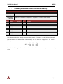
6.1
Numeric Formats
Floating point numbers displayed as ASCII text are presented in two formats: single precision floating
point and single precision fixed point. In order to conserve bandwidth each variable in the register has
associated with it either a floating or fixed point representation. Any time this variable is accessed using
a read/write register command or as Async output, the variable will always use its associated data
format.
6.2
Single Precision Floating Points
Single precision floating point numbers are represented with 7 significant digits and a 2 digit exponent.
Both the sign of the number and exponent are provided. The decimal point will always follow the first
significant digit. An ‘E’ will separate the significant digits from the exponential digits. Below are some
samples of correct single precision floating point numbers.
Single Precision Floating Point Number Examples
6.3
+9.999999E+99
-7.344409E-05
-1.234567E+01
+4.893203E+00
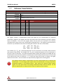
Fixed-Point Numbers
The fixed-point representation consists of a specified number of digits to the left and right of a fixed
decimal point. The registers that use fixed point representation and their associated formatting are
listed below. It is important to note that all numeric calculations onboard the VN-100 are performed
with 32-bit IEEE floating point numbers. For the sake of simplifying the output stream some of these
numbers are displayed in ASCII as fixed point as described below.
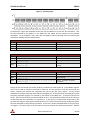
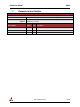
Table 14 – Floating Point Representation
Variable Type
Yaw, Pitch, Roll
Quaternion
Magnetic
Acceleration
Angular Rate
6.4
Fixed/Floating
Fixed
Fixed
Fixed
Fixed
Fixed
Register ID(s)
8, 27
9,10,11,12,13,14,15
10,13,15,17,20,27
11,13,14,18,20,27
12,14,15,19,20,27
Printf/Scanf
%+08.3f
%+09.6f
%+07.4f
%+07.3f
%+09.6f
Example
+082.763
+0.053362
-0.3647
-09.091
+00.001786
System Commands
This section describes the list of commands available on the VN-100 module. All commands are
available in both ASCII text (UART) and binary (SPI) command formats.
The table below lists the commands available along with some quick information about the commands.
The Text ID is used to specify the command when using the text command format and the Binary ID is
www.vectornav.com
33/102
VN-100 User Manual
UM001
used to specify the command when using the binary command format. More details about the
individual commands can be found in the referenced section.
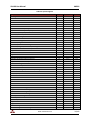
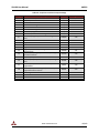
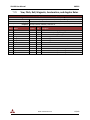
Table 15 – List of Available Commands
Command Name
Read Register
Write Register
Write Settings
Restore Factory Settings
Tare
Reset
Known Magnetic Disturbance
Known Acceleration Disturbance
Set Gyro Bias
6.4.1
Text ID
VNRRG
VNWRG
VNWNV
VNRFS
VNTAR
VNRST
VNKMD
VNKAD
VNSGB
Binary ID
0x01
0x02
0x03
0x04
0x05
0x06
0x08
0x09
0x0C
Section
6.4.1
6.4.2
6.4.3
0
6.4.5
6.4.6
6.4.7
6.4.8
6.4.9
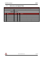
Read Register Command
This command allows the user to read any of the registers on the VN-100 module (see Section 7 for the
list of available registers). The only required parameter is the ID of the register to be read. The first
parameter of the response will contain the same register ID followed by a variable number of
parameters. The number of parameters and their formatting is specific to the requested register. Refer
to the appropriate register section contained in Section 7 for details on this formatting. If an invalid
register is requested, an error code will be returned. The error code format is described in Section 6.5.
Table 16 - Example Read Register Command
Example Command
UART Command
UART Response
SPI Command (8 bytes)
SPI Response (8 bytes)
6.4.2
Message
$VNRRG,5*46
$VNRRG,5,9600*65
01 05 00 00 80 25 00 00
00 01 05 00 80 25 00 00
(shown as hex)
(shown as hex)
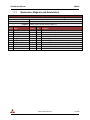
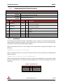
Write Register Command
This command is used to write data values to a specified register on the VN-100 module (see Section 7
for the list of available registers). The ID of the register to be written to is the first parameter. This is
followed by the data values specific to that register. Refer to the appropriate register section in Section
6 for this formatting. If an invalid register is requested, an error code will be returned. The error code
format is described in Section 6.5.
www.vectornav.com
34/102
VN-100 User Manual
UM001
Table 17 - Example Write Register Command
Example Command
UART Command
UART Response
SPI Command (8 bytes)
SPI Response (8 bytes)
6.4.3
Message
$VNWRG,5,9600*60
$VNWRG,5,9600*60
02 05 00 00 80 25 00 00
00 02 05 00 80 25 00 00
(shown as hex)
(shown as hex)
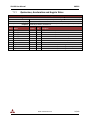
Write Settings Command
This command will write the current register settings into non-volatile memory. Once the settings are
stored in non-volatile (Flash) memory, the VN-100 module can be power cycled or reset, and the register
will be reloaded from non-volatile memory. The module can always be reset to the factory settings by
issuing the Restore Factory Settings command (Section 0) or by pulling pin 15 high during reset.
Table 18 - Example Write Settings Command
Example Command
UART Command
UART Response
SPI Command (8 bytes)
SPI Response (8 bytes)
Message
$VNWNV*57
$VNWNV*57
03 00 00 00 00 00 00 00
00 03 00 00 00 00 00 00
(shown as hex)
(shown as hex)
Due to limitations in the flash write speed the write settings command takes ~ 500ms to
complete. Any commands that are sent to the sensor during this time will be responded to
after the operation is complete.
6.4.4
Restore Factory Settings Command
This command will restore the VN-100 module’s factory default settings (see Section 8) and reset the
module. There are no parameters for this command. The module will respond to this command before
restoring the factory settings.
Table 19 - Example Restore Factory Settings Command
Example Command
UART Command
UART Response
SPI Command (8 bytes)
SPI Response (8 bytes)
6.4.5
Message
$VNRFS*5F
$VNRFS*5F
04 00 00 00 00 00 00 00
00 04 00 00 00 00 00 00
(shown as hex)
(shown as hex)
Tare Command
The Tare command will have the module zero out its current orientation. The effect of this command in
2D magnetic mode will be to set only the yaw angle to zero. In 3D heading mode the VN-100 will set the
yaw, pitch, and roll angles to zero. In 3D heading mode the VN-100 will also now measure yaw, pitch,
and roll relative to the alignment of the respective Z, Y, and X axis in 3D space when the tare command
was received. For more information on how to change the magnetic mode see Section 7.35.
www.vectornav.com
35/102
VN-100 User Manual
UM001
Table 20 - Example Tare Command
Example Command
UART Command
UART Response
SPI Command (8 bytes)
SPI Response (8 bytes)
Message
$VNTAR*5F
$VNTAR*5F
05 00 00 00 00 00 00 00
00 05 00 00 00 00 00 00
(shown as hex)
(shown as hex)
Avoid switching magnetic modes after issuing a tare command as this can lead to
unpredictable behavior. If you need to issue a tare command, first set the magnetic mode,
next issue a write settings command, and then reset the device. After reset you can issue a
tare command.
6.4.6
Reset Command
This command will reset the module. There are no parameters required for this command. The module
will first respond to the command and will then perform a reset. Upon a reset all registers will be
reloaded with the values saved in non-volatile memory. If no values are stored in non-volatile memory
then the device will default to factory settings. Also upon reset the VN-100 will re-initialize its Kalman
filter, thus the filter will take a few seconds to completely converge on the correct attitude and correct
for gyro bias. This command is equivalent in functionality to the hardware reset performed by pulling
pin 21 low.
Table 21 - Example Reset Command
Example Command
UART Command
UART Response
SPI Command (8 bytes)
SPI Response (8 bytes)
6.4.7
Message
$VNRST*4D
$VNRST*4D
06 00 00 00 00 00 00 00
00 06 00 00 00 00 00 00
(shown as hex)
(shown as hex)
Known Magnetic Disturbance Command
This command is used to notify the VN-100 that a magnetic disturbance is present. When the VN-100
receives this command it will tune out the magnetometer and will pause the current hard/soft iron
calibration if it is enabled. A single parameter is provided to tell the VN-100 whether the disturbance is
present or not.
0 – No Disturbance is present
1 – Disturbance is present
Table 22 - Example Magnetic Disturbance Command
Example Command
UART Command
UART Response
SPI Command (8 bytes)
SPI Response (8 bytes)
Message
$VNKMD,1*47
$VNKMD,1*47
08 01 00 00 00 00 00 00
00 08 01 00 00 00 00 00
www.vectornav.com
(shown as hex)
(shown as hex)
36/102
VN-100 User Manual
6.4.8
UM001
Known Acceleration Disturbance Command
This command is used to notify the VN-100 that an acceleration disturbance is present. When the VN100 receives this command it will tune out the accelerometer. A single parameter is provided to tell the
VN-100 whether the disturbance is present or not.
0 – No Disturbance is present
1 – Disturbance is present
Table 23 - Example Acceleration Disturbance Command
Example Command
UART Command
UART Response
SPI Command (8 bytes)
SPI Response (8 bytes)
6.4.9
Message
$VNKAD,1*4B
$VNKAD,1*4B
09 01 00 00 00 00 00 00
00 09 01 00 00 00 00 00
(shown as hex)
(shown as hex)
Set Gyro Bias Command
This command is used to save the current gyro bias estimate to memory for use at startup. Make sure
that the device remains perfectly still when you send this command. If this command is sent along with
a write settings command, after startup the VPE will use the saved gyro bias as opposed to assuming
that it is zero. This will reduce the time required to output a stable attitude and angular rate estimate.
Table 24 - Example Gyro Bias Command
Example Command
UART Command
UART Response
SPI Command (8 bytes)
SPI Response (8 bytes)
6.5
Message
$VNSGB*4E
$VNSGB*4E
0B 00 00 00 00 00 00 00
00 0B 00 00 00 00 00 00
(shown as hex)
(shown as hex)
System Error Codes
In the event of an error, the chip will output $VNERR, followed by an error code. The possible error
codes are listed in the table below with a description of the error.
Table 25 – Error Codes
Error Name
Code
Hard Fault
1
Serial Buffer Overflow
2
Invalid Checksum
Invalid Command
3
4
Not Enough Parameters
5
Too Many Parameters
Invalid Parameter
6
7
Description
If this error occurs, then the firmware on the chip has experienced a
hard fault exception. To recover from this error the processor will force
a restart, and a discontinuity will occur in the serial output. The
processor will restart within 50ms of a hard fault error.
The processor’s serial input buffer has experienced an overflow. The
processor has a 256 character input buffer.
The checksum for the received command was invalid.
The user has requested an invalid command.
The user did not supply the minimum number of required parameters
for the requested command.
The user supplied too many parameters for the requested command.
The user supplied a parameter for the requested command which was
www.vectornav.com
37/102
VN-100 User Manual
7
UM001
Invalid Register
Unauthorized Access
8
9
Watchdog Reset
10
Output Buffer Overflow
11
Insufficient Baud Rate
12
invalid.
An invalid register was specified.
The user does not have permission to write to this register.
A watchdog reset has occurred. In the event of a non-recoverable error
the internal watchdog will reset the processor within 50ms of the error.
The output buffer has experienced an overflow. The processor has a
2048 character output buffer.
The baud rate is not high enough to support the requested
asynchronous data output at the requested data rate.
System Registers
The VN-100 module contains a collection of registers used for configuring the module and accessing the
data it produces. These registers may be read or written to using the Read Register and Write Register
commands (Sections 6.4.1 and 6.4.2). When the module is rebooted or power-cycled, values written to
the registers will revert back to their previous values unless a Write Settings command has been issued
(Section 6.4.3) to save the registers to non-volatile memory.
Table 26 provides a quick reference for all of the registers and their associated properties. The second
column lists the Access ID, which is used to identify a specific register. The third column indicates the
width of the register in bytes (relevant only in SPI mode) and the last column provides the section
number where a more detailed explanation of the register may be found.
Each register may be read or written to using either serial or SPI communication modes. The specific
register sections that follow describe the format used by each communication mode.
www.vectornav.com
38/102
VN-100 User Manual
UM001
Table 26 –System Registers
Register Name
User Tag
Model Number
Hardware Revision
Serial Number
Firmware Version
Serial Baud Rate
Asynchronous Data Output Type
Asynchronous Data Output Frequency
Attitude (Yaw, Pitch, Roll)
Attitude (Quaternion)
Quaternion and Magnetic
Quaternion and Acceleration
Quaternion and Angular Rates
Quaternion, Magnetic and Acceleration
Quaternion, Acceleration and Angular Rates
Quaternion, Magnetic, Acceleration, and Angular Rates
Attitude (Directional Cosine Matrix)
Magnetic Measurements
Acceleration Measurements
Angular Rate Measurements
Magnetic, Acceleration, and Angular Rate Measurements
Magnetic and Gravity Reference Vectors
Filter Measurements Variance Parameters
Magnetic Hard/Soft Iron Compensation Parameters
Disturbance Tuning Parameters
Accelerometer Compensation
Reference Frame Rotation
Yaw, Pitch, Roll, Magnetic, Acceleration, and Angular Rates
Accelerometer Gain
Yaw, Pitch, Roll, and Calibrated Measurements
Communication Protocol Control
Communication Protocol Status
Synchronization Control
Synchronization Status
Filter Basic Control
VPE Control
Magnetometer Basic Tuning
Magnetometer Advanced Tuning
Accelerometer Basic Tuning
Accelerometer Advanced Tuning
Gyroscope Basic Tuning
Filter Simple Status
Gyro Startup Bias
Magnetometer Vector Calibration Control
Magnetometer Vector Calibration Status
Calculated Magnetometer Calibration
Indoor Heading Mode Control Register
www.vectornav.com
Access ID
0
1
2
3
4
5
6
7
8
9
10
11
12
13
14
15
16
17
18
19
20
21
22
23
24
25
26
27
28
29
30
31
32
33
34
35
36
37
38
39
40
42
43
44
46
47
48
Width (bytes)
20
24
4
12
4
4
4
4
3x4
4x4
7x4
7x4
7x4
10 x 4
10 x 4
13 x 4
9x4
3x4
3x4
3x4
9x4
6x4
10 x 4
12 x 4
4x4
12 x 4
9x4
12 x 4
4
13 x 4
7
44
20
12
16
4
9x4
9x4
9x4
9x4
9x4
28
3x4
4
28
12 x 4
8
Section
7.1
7.2
7.3
7.4
7.5
7.6
7.7
7.8
7.9
7.10
7.11
7.12
7.13
7.14
7.15
7.16
7.17
7.18
7.19
7.20
7.21
7.22
7.23
7.24
7.25
7.26
7.27
7.28
7.29
7.30
7.31
7.32
7.33
7.34
7.35
7.36
0
7.38
7.39
7.40
7.41
7.42
7.43
7.44
7.45
7.46
7.47
39/102
VN-100 User Manual
UM001
Register Name
Yaw, Pitch, Roll, True Body Acceleration, & Angular Rate
Yaw, Pitch, Roll, True Inertial Acceleration, & Angular Rate
Yaw, Pitch, Roll, & Inertial Calibrated Measurements
Raw Voltage Measurements
Calibrated Unfiltered Measurements
Kalman Filter State Vector
Kalman Filter Covariance Matrix Diagonal
www.vectornav.com
Access ID
239
240
241
251
252
253
254
Width (bytes)
9x4
9x4
12 x 4
10 x 4
10 x 4
7x4
6x4
Section
7.48
7.49
7.50
7.51
7.52
7.53
7.54
40/102
VN-100 User Manual
7.1
UM001
User Tag Register
Register ID :
Comment :
Size (Bytes):
Example Serial Read Register
Response:
Byte
Offset Name
0
Tag
User Tag
0
Firmware : v1.1 and up
Access : Read / Write
User assigned tag register. Any values can be assigned to this register. They will be
stored to flash upon issuing a write settings command.
20
$VNRRG,00,SENSOR_A14*52
Number
Format
C20
Unit
-
Description
User defined tag register. Up to 20 bytes or characters.
www.vectornav.com
41/102
VN-100 User Manual
7.2
UM001
Model Number Register
Register ID :
Comment :
Size (Bytes):
Example Serial Read Register
Response:
Byte
Offset Name
0
Product Name
1
Model Number
24
Model Number
Firmware :
v0.1 and up
Access :
Read Only
$VNRRG,01,VN-100*5A
Number
Format
C24
Unit
-
Description
Product name. 24 characters.
www.vectornav.com
42/102
VN-100 User Manual
7.3
UM001
Hardware Revision Register
Register ID :
Comment :
Size (Bytes):
Example Serial Read Register
Response:
Byte
Offset Name
0
Revision
Hardware Revision Register
2
Firmware : v0.1 and up
Hardware revision.
4
Access :
Read Only
$VNRRG,02,4*69
Number
Format
U4
Unit
-
Description
Hardware revision.
www.vectornav.com
43/102
VN-100 User Manual
7.4
UM001
Serial Number Register
Register ID :
Comment :
Size (Bytes):
Example Serial Read Register
Response:
Byte
Offset Name
0
SN[0]
4
SN[1]
8
SN[2]
3
Serial Number
12
Serial Number
Firmware :
v0.1 and up
Access :
Read Only
$VNRRG,03,0672FF574957824887212839*58
Number
Format
X4
X4
X4
Unit
-
Description
SN Section 1. 8 hexadecimal digits (4 bytes).
SN Section 2. 8 hexadecimal digits (4 bytes).
SN Section 3. 8 hexadecimal digits (4 bytes).
www.vectornav.com
44/102
VN-100 User Manual
7.5
UM001
Firmware Version Register
Register ID :
Comment :
Size (Bytes):
Example Serial Read Register
Response:
Byte
Offset Name
0
Major Version
1
Minor Version
2
Build
3
HotFix
Firmware Version Register
4
Firmware : v0.1 and up
Firmware version.
4
Access :
Read Only
$VNRRG,04,1.1.98.0*44
Number
Format
U1
U1
U1
U1
Unit
-
Description
Major release version of firmware.
Minor release version of firmware
Build number.
Hot fix number.
www.vectornav.com
45/102
VN-100 User Manual
Serial Baud Rate Register
7.6
Register ID :
Comment :
Size (Bytes):
Example Serial Read Register
Response:
Byte
Offset Name
0
Baud Rate
4
UM001
Serial Port
5
Serial baud rate.
4
Serial Baud Rate
Firmware :
v0.1 and up
Access :
Read / Write
$VNRRG,05,115200*5D
Number
Format
U4
Unit
-
U1
-
Description
Serial baud rate.
Optional. The serial port to change the baud rate on.
If this parameter is not provided then the baud rate will be
changed for the active serial port.
This register specifies the baud rate of the serial data bus. The table below specifies the associated baud
rate achieved when the register is set to one of the values listed in Table 27. The response for this
command will be sent after the baud rate is changed.
Table 27 – Baud Rate Settings
Acceptable
Baud Rates
9600
19200
38400
57600
115200
128000
230400
460800
921600
The serial port parameter in this register is optional. If it is not provided then the baud rate
will be changed on the active serial port. The response to this register will include the serial
port parameter if the optional parameter is provided. If the second parameter is not provided
then the response will not include this parameter.
Upon receiving a baud rate change request, the VN-100 will send the response prior to
changing the baud rate.
www.vectornav.com
46/102
VN-100 User Manual
Async Data Output Type Register
7.7
Register ID :
Comment :
Size (Bytes):
Example Serial Read Register
Response:
Byte
Offset Name
0
ADOR
4
UM001
Serial Port
Asynchronous Data Output Type
6
Firmware : v0.1 and up
Asynchronous data output type.
4
Access :
Read / Write
$VNRRG,06,0*69
Number
Format
U4
Unit
-
U1
-
Description
Output register.
Optional. The serial port to change the asynchronous data type
on. If this parameter is not provided then the ADOR will be
changed for the active serial port.
This register controls the type of data that will be asynchronously outputted by the module. With this
register, the user can specify which data register will be automatically outputted when it gets updated
with a new reading. Table 28 lists which registers can be set to asynchronously output, the value to
specify which register to output, and the header of the asynchronous data packet. Asynchronous data
output can be disabled by setting this register to zero. The asynchronous data output will be sent out
automatically at a frequency specified by the Async Data Output Frequency Register (Section 7.8).
The serial port parameter in this register is optional. If it is not provided then the ADOR will be
changed on the active serial port. The response to this register will include the serial port
parameter if the optional parameter is provided. If the second parameter is not provided then
the response will not include this parameter.
www.vectornav.com
47/102
VN-100 User Manual
UM001
Table 28 – Asynchronous Solution Output Settings
Setting
0
1
2
3
4
5
6
7
8
9
10
11
12
13
14
15
16
17
18
252
253
254
255
Asynchronous Solution Output Type
Asynchronous output turned off
Yaw, Pitch, Roll
Quaternion
Quaternion and Magnetic
Quaternion and Acceleration
Quaternion and Angular Rates
Quaternion, Magnetic and Acceleration
Quaternion, Acceleration and Angular Rates
Quaternion, Magnetic, Acceleration and Angular
Rates
Directional Cosine Orientation Matrix
Magnetic Measurements
Acceleration Measurements
Angular Rate Measurements
Magnetic, Acceleration, and Angular Rate
Measurements
Yaw, Pitch, Roll, Magnetic, Acceleration, and Angular
Rate Measurements
Yaw, Pitch, Roll, & Calibrated Measurements
Yaw, Pitch, Roll, Body True Acceleration, and Angular
Rates
Yaw, Pitch, Roll, Inertial True Acceleration, and
Angular Rates
Yaw, Pitch, Roll, Inertial Magnetic/Acceleration, and
Angular Rate Measurements
Raw Voltage Measurements
Calibrated Measurements
Kalman Filter State Vector
Kalman Filter Covariance Matrix Diagonal
www.vectornav.com
Header
N/A
VNYPR
VNQTN
VNQTM
VNQTA
VNQTR
VNQMA
VNQAR
Formatting Section
N/A
7.9
7.10
7.11
7.12
7.13
7.14
7.15
VNQMR
7.16
VNDCM
VNMAG
VNACC
VNGYR
7.17
7.18
7.19
7.20
VNMAR
7.21
VNYMR
7.28
VNYCM
7.30
VNYBA
7.48
VNYIA
7.49
VNICM
7.50
VNRAW
VNCMV
VNSTV
VNCOV
7.51
7.52
7.53
7.54
48/102
VN-100 User Manual
Async Data Output Frequency Register
7.8
Register ID :
Comment :
Size (Bytes):
Example Serial Read Register
Response:
Byte
Offset Name
0
ADOF
4
UM001
Serial Port
Asynchronous Data Output Frequency
7
Firmware : v0.1 and up
Asynchronous data output frequency.
4
Access :
Read / Write
$VNRRG,07,50*5D
Number
Format
U4
Unit
Hz
U1
-
Description
Output frequency.
Optional. The serial port to change the asynchronous data type
frequency on. If this parameter is not provided then the ADOF will
be changed for the active serial port.
Table 29 - ADOR Data Rates
Acceptable
Data Rates (Hz)
1
2
4
5
10
20
25
40
50
100
200
The serial port parameter in this register is optional. If it is not provided then the ADOF will be
changed on the active serial port. The response to this register will include the serial port
parameter if the optional parameter is provided. If the second parameter is not provided then
the response will not include this parameter.
www.vectornav.com
49/102
VN-100 User Manual
7.9
UM001
Attitude (Yaw, Pitch, Roll Format)
Register ID :
Comment :
Size (Bytes):
Example Serial Read Register
Response:
Byte
Offset Name
0
Yaw
4
Pitch
8
Roll
Yaw, Pitch, and Roll
8
Firmware : v0.1 and up
Attitude solution as yaw, pitch, and roll in degrees.
12
Access :
Read Only
$VNRRG,8,+006.271,+000.031,-002.000*66
Number
Format
F4
F4
F4
Unit
deg
deg
deg
Description
Yaw angle (heading).
Pitch angle.
Roll angle.
www.vectornav.com
50/102
VN-100 User Manual
7.10
UM001
Attitude Quaternion
Register ID :
Comment :
Size (Bytes):
Example Serial Read Register
Response:
Byte
Offset Name
0
Quat[0]
4
Quat[1]
8
Quat[2]
12
Quat[3]
Quaternion
9
Firmware :
Attitude solution as a quaternion.
16
v0.1 and up
Access :
Read Only
$VNRRG,9,-0.017386,-0.000303,+0.055490,+0.998308*4F
Number
Format
F4
F4
F4
F4
Unit
-
Description
Calculated attitude as quaternion.
Calculated attitude as quaternion.
Calculated attitude as quaternion.
Calculated attitude as quaternion. Scalar component.
This register contains four values representing the quaternion vector. The quaternion provides a
redundant, nonsingular attitude representation that is well suited for describing arbitrary, large
rotations. The quaternion is a non-dimensional 4x1 unit vector with the fourth value as the scalar term.
The fields of this register are represented with fixed point precision for the serial protocol and 32-bit
floating point precision for the SPI protocol. This is a read-only register. All filtering and other
mathematical operations performed by the VN-100 are performed using quaternions. The quaternion
used by the VN-100 has the following form.
[ ]
( )
[ ]
( )
[ ]
( )
[ ]
Where
( )
{ } is the principal axis and
www.vectornav.com
is the principal angle.
51/102
VN-100 User Manual
7.11
UM001
Quaternion and Magnetic
Register ID :
Comment :
Size (Bytes):
Example Serial Read Register
Response:
Byte
Offset Name
0
Quat[0]
4
Quat[1]
8
Quat[2]
12
Quat[3]
16
MagX
20
MagY
24
MagZ
Quaternion and Magnetic
10
Firmware : v0.1 and up
Attitude solution, and magnetic.
28
Access :
Read Only
$VNRRG,10,-0.017285,-0.000569,+0.053088,+0.998440,+1.0641,-0.2576,+3.0696*6E
Number
Format
F4
F4
F4
F4
F4
F4
F4
Unit
-
Description
Calculated attitude as quaternion.
Calculated attitude as quaternion.
Calculated attitude as quaternion.
Calculated attitude as quaternion. Scalar component.
Calibrated magnetometer measurement in x-axis.
Calibrated magnetometer measurement in y-axis.
Calibrated magnetometer measurement in z-axis.
www.vectornav.com
52/102
VN-100 User Manual
7.12
UM001
Quaternion and Acceleration
Register ID :
Comment :
Size (Bytes):
Example Serial Read Register
Response:
Byte
Offset Name
0
Quat[0]
4
Quat[1]
8
Quat[2]
12
Quat[2]
16
AccelX
20
AccelY
24
AccelZ
Quaternion and Acceleration
11
Firmware : v0.1 and up
Attitude solution and acceleration.
28
Access :
Read Only
$VNRRG,11,-0.017348,-0.000265,+0.053568,+0.998414,-00.003,+00.344,-09.841*62
Number
Format
F4
F4
F4
F4
F4
F4
F4
Unit
m/s2
m/s2
m/s2
Description
Calculated attitude as quaternion.
Calculated attitude as quaternion.
Calculated attitude as quaternion.
Calculated attitude as quaternion. Scalar component.
Calibrated accelerometer measurement in x-axis.
Calibrated accelerometer measurement in y-axis.
Calibrated accelerometer measurement in z-axis.
www.vectornav.com
53/102
VN-100 User Manual
7.13
UM001
Quaternion and Angular Rates
Register ID :
Comment :
Size (Bytes):
Example Serial Read Register
Response:
Byte
Offset Name
0
Quat[0]
4
Quat[1]
8
Quat[2]
12
Quat[3]
16
GyroX
20
GyroY
24
GyroZ
Quaternion, Acceleration, and Angular Rates
12
Firmware : v0.1 and up
Access : Read Only
Attitude solution, and compensated angular rates.
28
$VNRRG,12,-0.017030,-0.000634,+0.055279,+0.998326,-0.000748,+0.001867,0.001236*6B
Number
Format Unit Description
F4
Calculated attitude as quaternion.
F4
Calculated attitude as quaternion.
F4
Calculated attitude as quaternion.
F4
Calculated attitude as quaternion. Scalar component.
F4
rad/s Calibrated & filter bias compensated angular rate in x-axis.
F4
rad/s Calibrated & filter bias compensated angular rate in y-axis.
F4
rad/s Calibrated & filter bias compensated angular rate in z-axis.
www.vectornav.com
54/102
VN-100 User Manual
7.14
UM001
Quaternion, Magnetic and Acceleration
Register ID :
Comment :
Size (Bytes):
Example Serial Read Register
Response:
Byte
Offset Name
0
Quat[0]
4
Quat[1]
8
Quat[2]
12
Quat[3]
16
MagX
20
MagY
24
MagZ
28
AccelX
32
AccelY
36
AccelZ
Quaternion, Magnetic, and Acceleration
13
Firmware : v0.1 and up
Access : Read Only
Attitude solution, magnetic, and acceleration.
40
$VNRRG,13,-0.017198,-0.000737,+0.054042,+0.998390,+1.0670,0.2502,+3.0567,+00.041,+00.313,-09.867*77
Number
Format Unit Description
F4
Calculated attitude as quaternion.
F4
Calculated attitude as quaternion.
F4
Calculated attitude as quaternion.
F4
Calculated attitude as quaternion. Scalar component.
F4
Calibrated magnetometer measurement in x-axis.
F4
Calibrated magnetometer measurement in y-axis.
F4
Calibrated magnetometer measurement in z-axis.
2
F4
m/s
Calibrated accelerometer measurement in x-axis.
F4
m/s2 Calibrated accelerometer measurement in y-axis.
F4
m/s2 Calibrated accelerometer measurement in z-axis.
www.vectornav.com
55/102
VN-100 User Manual
7.15
UM001
Quaternion, Acceleration and Angular Rates
Register ID :
Comment :
Size (Bytes):
Example Serial Read Register
Response:
Byte
Offset Name
0
Quat[0]
4
Quat[1]
8
Quat[2]
12
Quat[3]
16
AccelX
20
AccelY
24
AccelZ
28
GyroX
32
GyroY
36
GyroZ
Quaternion, Acceleration, and Angular Rates
14
Firmware : v0.1 and up
Access : Read Only
Attitude solution, acceleration, and compensated angular rates.
40
$VNRRG,14,-0.017270,-0.000926,+0.056119,+0.998274,+00.005,+00.332,-09.822,0.000738,+0.000312,+0.002216*76
Number
Format Unit Description
F4
Calculated attitude as quaternion.
F4
Calculated attitude as quaternion.
F4
Calculated attitude as quaternion.
F4
Calculated attitude as quaternion. Scalar component.
F4
m/s2 Calibrated accelerometer measurement in x-axis.
F4
m/s2 Calibrated accelerometer measurement in y-axis.
F4
m/s2 Calibrated accelerometer measurement in z-axis.
F4
rad/s Calibrated & filter bias compensated angular rate in x-axis.
F4
rad/s Calibrated & filter bias compensated angular rate in y-axis.
F4
rad/s Calibrated & filter bias compensated angular rate in z-axis.
www.vectornav.com
56/102
VN-100 User Manual
7.16
UM001
Quaternion, Magnetic, Acceleration and Angular Rates
Quaternion, Magnetic, Acceleration, and Angular Rates
Register ID : 15
Firmware : v0.1 and up
Access : Read Only
Comment : Attitude solution, magnetic, acceleration, and compensated angular rates.
Size (Bytes): 52
Example Serial Read Register $VNRRG,15,-0.017057,-0.000767,+0.056534,+0.998255,+1.0670,-0.2568,+3.0696,Response: 00.019,+00.320,-09.802,-0.002801,-0.001186,-0.001582*65
Byte
Number
Offset Name
Format Unit Description
0
Quat[0]
F4
Calculated attitude as quaternion.
4
Quat[1]
F4
Calculated attitude as quaternion.
8
Quat[2]
F4
Calculated attitude as quaternion.
12
Quat[3]
F4
Calculated attitude as quaternion. Scalar component.
16
MagX
F4
Calibrated magnetometer measurement in x-axis.
20
MagY
F4
Calibrated magnetometer measurement in y-axis.
24
MagZ
F4
Calibrated magnetometer measurement in z-axis.
2
28
AccelX
F4
m/s
Calibrated accelerometer measurement in x-axis.
32
AccelY
F4
m/s2 Calibrated accelerometer measurement in y-axis.
36
AccelZ
F4
m/s2 Calibrated accelerometer measurement in z-axis.
40
GyroX
F4
rad/s Calibrated & filter bias compensated angular rate in x-axis.
44
GyroY
F4
rad/s Calibrated & filter bias compensated angular rate in y-axis.
48
GyroZ
F4
rad/s Calibrated & filter bias compensated angular rate in z-axis.
www.vectornav.com
57/102
VN-100 User Manual
7.17
Register ID :
Comment :
Size (Bytes):
Example Serial
Read Register
Response:
Byte
Offset Name
0
C[0,0]
4
C[0,1]
8
C[0,2]
12
C[1,0]
16
C[1,1]
20
C[1,2]
24
C[2,0]
28
C[2,1]
32
C[2,2]
UM001
Attitude (Directional Cosine Orientation Matrix)
Attitude Directional Cosine Matrix
16
Firmware : v0.1 and up
The calculated attitude as a directional cosine matrix.
36
Access :
Read Only
$VNRRG,16,+9.941386E-01,-1.080712E-01,-3.024663E-03,+1.081114E-01,+9.935566E01,+3.401868E-02,-6.712652E-04,-3.414628E-02,+9.994167E-01*0F
Number
Format
F4
F4
F4
F4
F4
F4
F4
F4
F4
Unit
-
Description
This register contains the attitude directional cosine matrix. This matrix is a valid 3x3 rotation matrix.
Nine parameters are returned from this command, and the terms are mapped to a 3x3 matrix as
follows,
[
]
The ordering of this register’s nine values is shown below. All nine numbers are represented as floating
point.
www.vectornav.com
58/102
VN-100 User Manual
7.18
UM001
Magnetic Measurements
Register ID :
Comment :
Size (Bytes):
Example Serial Read Register
Response:
Byte
Offset Name
0
MagX
4
MagY
8
MagZ
Magnetic Measurements
17
Firmware :
Magnetometer measurements.
12
v0.1 and up
Access :
Read Only
$VNRRG,17,+1.0647,-0.2498,+3.0628*66
Number
Format
F4
F4
F4
Unit
-
Description
Calibrated magnetometer measurement in x-axis.
Calibrated magnetometer measurement in y-axis.
Calibrated magnetometer measurement in z-axis.
www.vectornav.com
59/102
VN-100 User Manual
7.19
UM001
Acceleration Measurements
Register ID :
Comment :
Size (Bytes):
Example Serial Read Register
Response:
Byte
Offset Name
0
AccelX
4
AccelY
8
AccelZ
Acceleration Measurements
18
Firmware : v0.1 and up
Acceleration measurements.
12
Access :
Read Only
$VNRRG,18,+00.013,+00.354,-09.801*65
Number
Format
F4
F4
F4
Unit
m/s2
m/s2
m/s2
Description
Calibrated accelerometer measurement in x-axis.
Calibrated accelerometer measurement in y-axis.
Calibrated accelerometer measurement in z-axis.
www.vectornav.com
60/102
VN-100 User Manual
7.20
UM001
Angular Rate Measurements
Register ID :
Comment :
Size (Bytes):
Example Serial Read Register
Response:
Byte
Offset Name
0
GyroX
4
GyroY
8
GyroZ
Angular Rate Measurements
19
Firmware : v0.1 and up
Compensated angular rates.
12
Access :
Read Only
$VNRRG,19,+0.002112,-0.000362,-0.000876*6C
Number
Format
F4
F4
F4
Unit
rad/s
rad/s
rad/s
Description
Calibrated & filter bias compensated angular rate in x-axis.
Calibrated & filter bias compensated angular rate in y-axis.
Calibrated & filter bias compensated angular rate in z-axis.
www.vectornav.com
61/102
VN-100 User Manual
7.21
UM001
Magnetic, Acceleration and Angular Rates
Register ID :
Comment :
Size (Bytes):
Example Serial Read Register
Response:
Byte
Offset Name
0
MagX
4
MagY
8
MagZ
12
AccelX
16
AccelY
20
AccelZ
24
GyroX
28
GyroY
32
GyroZ
Magnetic, Acceleration, and Angular Rates
20
Firmware : v0.1 and up
Access : Read Only
Magnetic, acceleration, and compensated angular rates.
36
$VNRRG,20,+1.0684,-0.2578,+3.0649,-00.005,+00.341,-09.780,-0.000963,+0.000840,0.000466*64
Number
Format Unit Description
F4
Calibrated magnetometer measurement in x-axis.
F4
Calibrated magnetometer measurement in y-axis.
F4
Calibrated magnetometer measurement in z-axis.
2
F4
m/s
Calibrated accelerometer measurement in x-axis.
F4
m/s2 Calibrated accelerometer measurement in y-axis.
F4
m/s2 Calibrated accelerometer measurement in z-axis.
F4
rad/s Calibrated & filter bias compensated angular rate in x-axis.
F4
rad/s Calibrated & filter bias compensated angular rate in y-axis.
F4
rad/s Calibrated & filter bias compensated angular rate in z-axis.
www.vectornav.com
62/102
VN-100 User Manual
7.22
UM001
Magnetic and Gravity Reference Vectors
Register ID :
Comment :
Size (Bytes):
Example Serial Read
Register Response:
Byte
Offset Name
0
MagRefX
4
MagRefY
8
MagRefZ
12
AccRefX
16
AccRefY
20
AccRefZ
Magnetic and Gravity Reference Vectors
21
Firmware : v0.1 and up
Magnetic and gravity reference vectors.
24
Access :
Read / Write
$VNRRG,21,1,0,1.8,0,0,-9.79375*53
Number
Format
F4
F4
F4
F4
F4
F4
Unit
N/A
N/A
N/A
m/s^2
m/s^2
m/s^2
Description
X-Axis Magnetic Reference
Y-Axis Magnetic Reference
Z-Axis Magnetic Reference
X-Axis Gravity Reference
Y-Axis Gravity Reference
Z-Axis Gravity Reference
www.vectornav.com
63/102
VN-100 User Manual
UM001
Filter Measurements Variance Parameters
7.23
Register ID :
Comment :
Size (Bytes):
Example Serial
Read Register
Response:
Byte
Offset Name
Filter Measurement Variance Parameters
22
Firmware : v0.1 and up
Attitude Kalman Filter measurement uncertainty variances.
40
Access :
Read / Write
$VNRRG,22,5E-08,3E-06,3E-06,3E-06,0.5,0.5,0.5,0.001,0.001,0.001*7F
Number
Format
Unit
Description
0
RRW
F4
Variance - Angular Walk
4
ARWX
F4
Variance – X Axis Angular Rate
8
ARWY
F4
Variance – Y Axis Angular Rate
12
ARWZ
F4
Variance – Z Axis Angular Rate
16
20
24
VMAGX
VMAGY
VMAGZ
F4
F4
F4
N/A
N/A
N/A
28
VACCX
F4
( )
Variance – X Axis Acceleration
32
VACCY
F4
( )
Variance – Y Axis Acceleration
36
VACCZ
F4
( )
Variance – Z Axis Acceleration
Variance – X Axis Magnetic
Variance – Y Axis Magnetic
Variance – Z Axis Magnetic
This register is not used when VPE is enabled.
www.vectornav.com
64/102
VN-100 User Manual
7.24
Register ID :
Comment :
Size (Bytes):
Example Serial
Read Register
Response:
Byte
Offset Name
0
C[0,0]
4
C[0,1]
8
C[0,2]
12
C[1,0]
16
C[1,1]
20
C[1,2]
24
C[2,0]
28
C[2,1]
32
C[2,2]
36
B[0]
40
B[1]
44
B[2]
UM001
Magnetic Hard/Soft Iron Compensation Parameters
Magnetic Hard/Soft Iron Compensation Parameters
23
Firmware : v0.1 and up
Allows the magnetometer to be compensated for hard/soft iron effects.
48
Access :
Read / Write
$VNRRG,23,1,0,0,0,1,0,0,0,1,0,0,0*73
Number
Format
F4
F4
F4
F4
F4
F4
F4
F4
F4
F4
F4
F4
Unit
-
Description
This register contains twelve values representing the hard and soft iron compensation parameters. The
magnetic measurements are compensated for both hard and soft iron using the following model. Under
normal circumstances this register can be left in its factory default state. In the event that there are
disturbances in the magnetic field due to hard or soft iron effects, then these registers allow for further
compensation. These registers can also be used to compensate for significant changes to the
magnetometer bias, gain, and axis alignment during installation. Note that this magnetometer
compensation is separate from the compensation that occurs during the calibration process at the
factory. Setting this register to the default state of an identity matrix and zero offset will not eliminate
the magnetometer gain, bias, and axis alignment that occur during factory calibration. These registers
only need to be changed from their default values in the event that hard/soft iron compensation needs
to be performed, or changes in bias, gain, and axis alignment have occurred at some point between the
times the chip was calibrated at the factory and when it is used in the field.
{ }
[
] {
}
} are components of the measured magnetic field. The {X, Y, Z} variables are
The variables {
the new magnetic field measurements outputted after compensation for hard/soft iron effects. All
twelve numbers are represented by single-precision floating points.
www.vectornav.com
65/102
VN-100 User Manual
7.25
UM001
Filter Active Tuning Parameters
Register ID :
Comment :
Size (Bytes):
Example Serial Read
Register Response:
Byte
Offset Name
0
MagGain
4
AccGain
8
MagMemory
12
AccMemory
Filter Active Tuning Parameters
24
Firmware : v0.1 and up
Access : Read / Write
Legacy active tuning parameters. Supported for reverse compatibility. For new designs it is
recommended to use the adaptive tuning feature in VPE Magnetometer Basic Tuning Register
(Section 0) and the VPE Accelerometer Basic Tuning Register (Section 7.39).
16
$VNRRG,24,0,0,0.99,0.9*4C
Number
Format
F4
F4
F4
F4
Unit
-
Description
Magnetic Disturbance Gain [0 to 10].
Acceleration Disturbance Gain [0 to 10].
Magnetic Disturbance Memory [0 to 1].
Acceleration Disturbance Memory [0 to 1].
www.vectornav.com
66/102
VN-100 User Manual
7.26
UM001
Accelerometer Compensation
Register ID :
Comment :
Size (Bytes):
Example Serial Read
Register Response:
Byte
Offset Name
0
C[0,0]
4
C[0,1]
8
C[0,2]
12
C[1,0]
16
C[1,1]
20
C[1,2]
24
C[2,0]
28
C[2,1]
32
C[2,2]
36
B[0]
40
B[1]
44
B[2]
Accelerometer Compensation
25
Firmware : v0.1 and up
Access : Read / Write
Allows the accelerometer to be further compensated for scale factor, misalignment, and bias
errors.
48
$VNRRG,25,1,0,0,0,1,0,0,0,1,0,0,0*75
Number
Format
F4
F4
F4
F4
F4
F4
F4
F4
F4
F4
F4
F4
Unit
-
Description
This register contains twelve values representing the accelerometer compensation parameters. The
accelerometer measurements are compensated for changes in bias, gain, and axis alignment that can
occur during the installation of the chip on the customer’s board using the following model. Under
normal circumstances this register can be left in its factory default state. In the event that there are
significant changes to the accelerometer bias, gain, and axis alignment during installation, then these
registers allow for further compensation. Note that this accelerometer compensation is separate from
the compensation that occurs during the calibration process at the factory. Setting this register to the
default state of an identity matrix and zero offset will not eliminate the accelerometer gain, bias, and
axis alignment that occur during factory calibration. These registers only need to be changed from their
default values in the event that changes in bias, gain, and axis alignment have occurred at some point
between the times the chip was calibrated at the factory and when it is used in the field.
{ }
[
] {
}
} are components of the measured acceleration. The {X, Y, Z} variables are the
The variables {
new acceleration measurements outputted after compensation for changes during sensor mounting. All
twelve numbers are represented by single-precision floating points.
www.vectornav.com
67/102
VN-100 User Manual
7.27
UM001
Reference Frame Rotation
Register ID :
Comment :
Size (Bytes):
Example Serial Read Register
Response:
Byte
Offset Name
0
C[0,0]
4
C[0,1]
8
C[0,2]
12
C[1,0]
16
C[1,1]
20
C[1,2]
24
C[2,0]
28
C[2,1]
32
C[2,2]
Reference Frame Rotation
26
Firmware : v0.1 and up
Access : Read / Write
Allows the measurements of the VN-100 to be rotated into a different reference
frame.
36
$VNRRG,26,1,0,0,0,1,0,0,0,1*6A
Number
Format
F4
F4
F4
F4
F4
F4
F4
F4
F4
Unit
-
Description
This register contains a transformation matrix that allows for the transformation of measured
acceleration, magnetic, and angular rates from the body frame of the VN-100 to any other arbitrary
frame of reference. The use of this register allows for the sensor to be placed in any arbitrary
orientation with respect to the user’s desired body coordinate frame. This register can also be used to
correct for any orientation errors due to mounting the VN-100 on the user’s circuit board.
{ }
[
] { }
} are a measured parameter such as acceleration in the body reference frame
The variables {
} are a measured parameter such as acceleration in
with respect to the VN-100. The variables {
the user’s frame of reference. The reference frame rotation register thus needs to be loaded with the
transformation matrix that will transform measurements from the body reference frame of the VN-100
to the desired user frame of reference. It is crucial that these two frames of reference be rigidly
attached to each other. All nine numbers are represented by single-precision floating points.
The reference frame rotation is performed on all vector measurements prior to entering the
attitude filter. As such changing this register while the attitude filter is running may lead to
unexpected behavior in the attitude output. After setting the reference frame rotation
register to its new value send a write settings command and then reset the VN-100. This will
allow the attitude filter to startup with the newly set reference frame rotation.
www.vectornav.com
68/102
VN-100 User Manual
7.28
UM001
Yaw, Pitch, Roll, Magnetic, Acceleration, and Angular Rates
Yaw, Pitch, Roll, Magnetic, Acceleration, and Angular Rates
Register ID : 27
Firmware : v0.1 and up
Access : Read Only
Comment : Attitude solution, magnetic, acceleration, and compensated angular rates.
Size (Bytes): 48
Example Serial Read Register $VNRRG,27,+006.380,+000.023,-001.953,+1.0640,-0.2531,+3.0614,+00.005,+00.344,Response: 09.758,-0.001222,-0.000450,-0.001218*4F
Byte
Number
Offset Name
Format Unit Description
0
Yaw
F4
deg Calculated attitude heading angle in degrees.
4
Pitch
F4
deg Calculated attitude pitch angle in degrees.
8
Roll
F4
deg Calculated attitude roll angle in degrees.
12
MagX
F4
Calibrated magnetometer measurement in x-axis.
16
MagY
F4
Calibrated magnetometer measurement in y-axis.
20
MagZ
F4
Calibrated magnetometer measurement in z-axis.
24
AccelX
F4
m/s2 Calibrated accelerometer measurement in x-axis.
28
AccelY
F4
m/s2 Calibrated accelerometer measurement in y-axis.
32
AccelZ
F4
m/s2 Calibrated accelerometer measurement in z-axis.
36
GyroX
F4
rad/s Calibrated & filter bias compensated angular rate in x-axis.
40
GyroY
F4
rad/s Calibrated & filter bias compensated angular rate in y-axis.
44
GyroZ
F4
rad/s Calibrated & filter bias compensated angular rate in z-axis.
www.vectornav.com
69/102
VN-100 User Manual
7.29
UM001
Accelerometer Gain
Register ID :
Comment :
Size (Bytes):
Example Serial Read Register
Response:
Byte
Offset Name
0
AccelGain
Accelerometer Gain
28
Firmware :
Controls the accelerometer gain.
4
v0.1 to v0.8
Access :
Read / Write
$VNRRG,28,0*65
Number
Format
U4
Unit
-
Description
Accelerometer Gain
Table 30 – Accelerometer Gain
Register Value
0
1
Accelerometer Gain
±2g
±5g
Hardware version 4 and higher uses the ADXL325 which does not support the selectable gain.
For this hardware version the devices will always operate at ±5g regardless of the value of
this register.
www.vectornav.com
70/102
VN-100 User Manual
7.30
UM001
Yaw, Pitch, Roll, & Calibrated Measurements
Register ID :
Comment :
Size (Bytes):
Example Serial Read Register
Response:
Byte
Offset Name
0
Yaw
4
Pitch
8
Roll
12
MagX
16
MagY
20
MagZ
24
AccelX
28
AccelY
32
AccelZ
36
GyroX
40
GyroY
44
GyroZ
48
Temp
Yaw, Pitch, Roll, & Calibrated Measurements
29
Firmware : v0.1 and up
Access : Read Only
Attitude solution as yaw, pitch, roll and IMU calibrated measurements.
52
$VNRRG,29,+006.536,+000.031,-001.968,+1.0662,-0.2537,+3.0664,+00.018,+00.323,09.839,-0.017771,+0.032381,+0.004126,+25.5*5B
Number
Format Unit Description
F4
deg Calculated attitude heading angle in degrees.
F4
deg Calculated attitude pitch angle in degrees.
F4
deg Calculated attitude roll angle in degrees.
F4
Calibrated magnetometer measurement in x-axis.
F4
Calibrated magnetometer measurement in y-axis.
F4
Calibrated magnetometer measurement in z-axis.
F4
m/s2 Calibrated accelerometer measurement in x-axis.
F4
m/s2 Calibrated accelerometer measurement in y-axis.
F4
m/s2 Calibrated accelerometer measurement in z-axis.
F4
rad/s Calibrated un-compensated angular rate in x-axis.
F4
rad/s Calibrated un-compensated angular rate in y-axis.
F4
rad/s Calibrated un-compensated angular rate in z-axis.
F4
C
Calibrated temperature in degrees Celsius.
www.vectornav.com
71/102
VN-100 User Manual
UM001
Communication Protocol Control
7.31
Register ID :
Comment :
Size (Bytes):
Example Serial Read Register
Response:
Byte
Offset Name
Communication Protocol Control
30
Firmware : v1.1 and up
Access : Read / Write
Contains parameters that control settings relating to the communication protocol
used to communicate with the VN-100.
7
$VNRRG,30,0,0,0,0,1,0,1*6C
Number
Format
Unit
0
SerialCount
U1
-
1
SerialStatus
U1
-
2
SPICount
U1
-
3
SPIStatus
U1
-
4
5
6
SerialChecksum
SPIChecksum
ErrorMode
U1
U1
U1
-
7.31.1
Description
Provides the ability to append a counter to the end of the serial
asynchronous messages.
Provides the ability to append the status to the end of the serial
asynchronous messages.
Provides the ability to append a counter to the end of the SPI
packets.
Provides the ability to append the status to the end of the SPI
packets.
Choose the type of checksum used for serial communications.
Choose the type of checksum used for the SPI communications.
Choose the action taken when errors are generated.
SerialCount
The SerialCount field provides a means of appending a time or counter to the end of all asynchronous
communication messages transmitted on the serial interface. The values for each of these counters
come directly from the Synchronization Status Register.
With the SerialCount field set to OFF a typical serial asynchronous message would appear as the
following:
$VNYPR,+010.071,+000.278,-002.026*60
With the SerialCount field set to one of the non-zero values the same asynchronous message would
appear instead as:
$VNYPR,+010.071,+000.278,-002.026,T1162704*2F
When the SerialCount field is enabled the counter will always be appended to the end of the message
just prior to the checksum. The counter will be preceded by the T character to distinguish it from the
status field.
Table 31 – SerialCount Field
Mode
NONE
SYNCIN_COUNT
SYNCIN_TIME
SYNCOUT_COUNT
Value
0
1
2
3
Description
OFF
SyncIn Counter
SyncIn Time
SyncOut Counter
www.vectornav.com
72/102
VN-100 User Manual
7.31.2
UM001
SerialStatus
The SerialStatus field provides a means of tracking real-time status information pertaining to the overall
state of the sensor measurements and onboard filtering algorithm. This information is very useful in
situations where action must be taken when certain crucial events happen such as the detection of gyro
saturation or magnetic interference. As with the SerialCount, a typical serial asynchronous message
would appear as the following:
$VNYPR,+010.071,+000.278,-002.026*60
With the SerialStatus field set to one of the non-zero values, the same asynchronous message would
appear instead as:
$VNYPR,+010.071,+000.278,-002.026,S0000*1F
When the SerialStatus field is enabled the status will always be appended to the end of the message just
prior to the checksum. If both the SerialCount and SerialStatus are enabled then the SerialStatus will be
displayed first. The counter will be preceded by the S character to distinguish it from the counter field.
The status consists of 4 hexadecimal characters.
Table 32 – AsyncStatus
Value
0
1
7.31.3
Description
OFF
ON
SPICount
The SPICount field provides a means of appending a time or counter to the end of all SPI packets. The
values for each of these counters come directly from the Synchronization Status Register.
Table 33 – SPICount Field
Mode
NONE
SYNCIN_COUNT
SYNCIN_TIME
SYNCOUT_COUNT
7.31.4
Value
0
1
2
3
Description
OFF
SyncIn Counter
SyncIn Time
SyncOut Counter
SPIStatus
The AsyncStatus field provides a means of tracking real-time status information pertaining to the overall
state of the sensor measurements and onboard filtering algorithm. This information is very useful in
situations where action must be taken when certain crucial events happen such as the detection of gyro
saturation or magnetic interference.
Table 34 – SPIStatus
Value
0
1
Description
OFF
ON
www.vectornav.com
73/102
VN-100 User Manual
7.31.5
UM001
SerialChecksum
This field controls the type of checksum used for the serial communications. Normally the VN-100 uses
an 8-bit checksum identical to the type used for normal GPS NMEA packets. This form of checksum
however offers only a limited means of error checking. As an alternative a full 16-bit CRC (CRC16-CCITT
with polynomial = 0x07) is also offered. The 2-byte CRC value is printed using 4 hexadecimal digits.
Table 35 – SerialChecksum
Value
0
1
2
7.31.6
Description
OFF
8-Bit Checksum
16-Bit CRC
SPIChecksum
This field controls the type of checksum used for the SPI communications. The checksum is appended to
the end of the binary data packet. The 16-bit CRC is identical to the one described above for the
SerialChecksum.
Table 36 – SPIChecksum
Value
0
1
2
7.31.7
Description
OFF
8-Bit Checksum
16-Bit CRC
ErrorMode
This field controls the type of action taken by the VN-100 when an error event occurs. If the send error
mode is enabled then a message similar to the one shown below will be sent on the serial bus when an
error event occurs.
$VNERR,03*72
Regardless of the state of the ErrorMode, the number of error events is always recorded and is made
available in the SysErrors field of the Communication Protocol Status Register.
Table 37 – ErrorMode
Value
0
1
2
7.31.8
Description
Ignore Error
Send Error
Send Error and set ADOR register to OFF
Example Async Messages
The following table shows example asynchronous messages with the AsyncCount and the AsyncStatus
values appended to the end.
www.vectornav.com
74/102
VN-100 User Manual
Example Type
Async Message with
AsyncCount Enabled
Async Message with
AsyncStatus Enabled
Async Message with
AsyncCount and
AsyncStatus Enabled
UM001
Message
$VNYPR,+010.071,+000.278,-002.026,T1162704*2F
$VNYPR,+010.071,+000.278,-002.026,S0000*1F
$VNYPR,+010.071,+000.278,-002.026,T1162704,S0000*50
www.vectornav.com
75/102
VN-100 User Manual
7.32
UM001
Communication Protocol Status
Communication Protocol Status
Register ID :
Comment :
Size (Bytes):
Example Serial Read Register
Response:
Byte
Offset
0
4
8
9
10
11
12
Name
NumParsedSerialMessages
NumParsedSPIMessages
MaxUsageSerialRXBuffer
MaxUsageSerialTXBuffer
MaxUsageSPIRXBuffer
MaxUsageSPITXBuffer
SysErrors
Read /
Write
Contains parameters which allow the timing of the VN-100 to be synchronized with
external devices.
44
31
Firmware :
v1.1 and up
Access :
$VNRRG,31,25,0,6,11,0,0,0,0,0,0,0,0,0,0,0,0,0,0,0,0,0,0*70
Number
Format
U4
U4
U1
U1
U1
U1
U2[16]
Unit
%
%
%
%
-
Description
Number of successfully parsed serial messages received
Number of successfully parsed SPI messages received
Maximum percent usage of serial incoming buffer
Maximum percent usage of serial outgoing buffer
Maximum percent usage of SPI incoming buffer
Maximum percent usage of SPI outgoing buffer
Total number of each type of system error received
Writing zero to any field will reset the status counter. Writing any other value other than zero
will not have an effect.
www.vectornav.com
76/102
VN-100 User Manual
Synchronization Control
7.33
Register ID :
Comment :
Size (Bytes):
Example Serial Read
Register Response:
Byte
Offset
0
1
2
4
8
9
10
12
16
Name
SyncInMode
SyncInEdge
SyncInSkipFactor
RESERVED
SyncOutMode
SyncOutPolarity
SyncOutSkipFactor
SyncOutPulseWidth
RESERVED
7.33.1
UM001
Synchronization Control
32
Firmware : v1.1 and up
Access : Read / Write
Contains parameters which allow the timing of the VN-100 to be synchronized with
external devices.
20
$VNRRG,32,0,0,0,0,3,0,0,500000,0*58
Number
Format
U1
U1
U2
U4
U1
U1
U2
U4
U4
Unit
ns
ns
Description
Input signal synchronization mode
Input signal synchronization edge selection
Input signal trigger skip factor
Reserved for future use. Defaults to 0.
Output synchronization signal mode
Output synchronization signal polarity
Output synchronization signal skip factor
Output synchronization signal pulse width
Reserved for future use. Defaults to 0.
SyncInMode
The SyncInMode register controls the behavior of the SyncIn event. If the mode is set to COUNT then
the internal clock will be used to control the ADC timing. If SyncInMode is set to ASYNC then the ADC
loop will run on a SyncIn event. The relationship between the SyncIn event and a SyncIn trigger is
defined by the SyncInEdge and SyncInSkipFactor parameters. It is very important to note that the VN100 must always operate at an internal rate of 200Hz. If the SyncIn event is used to control the ADC
sampling, then the SyncIn event must be kept always at 200Hz. If set to ASYNC then the VN-100 will
output asynchronous serial messages upon each trigger event.
Table 38 – SyncIn Mode
Mode
COUNT2
ADC2
ASYNC2
COUNT
ADC
ASYNC
Pin
SYNC_IN_2
SYNC_IN_2
SYNC_IN_2
SYNC_IN
SYNC_IN
SYNC_IN
Value
0
1
2
3
4
5
Description
Count number of trigger events on SYNC_IN_2 (pin 15).
Start ADC sampling on trigger of SYNC_IN_2 (pin 15).
Output asynchronous message on trigger of SYNC_IN_2 (pin 15).
Count number of trigger events on SYNC_IN (pin 22).
Start ADC sampling on trigger of SYNC_IN (pin 22).
Output asynchronous message on trigger of SYNC_IN (pin 22).
For firmware version 1.1.141.0 and higher the SyncIn is set by default to use pin 22. For
reverse compatibility with previous firmware revisions it is possible to remap the SyncIn pin to
operate on pin 15 instead. For future designs it is recommended that pin 22 is used for the
SyncIn feature.
www.vectornav.com
77/102
VN-100 User Manual
7.33.2
UM001
SyncInEdge
The SyncInEdge register controls the type of edge the signal is set to trigger on. The factory default
state is to trigger on a rising edge.
Table 39 – SyncInEdge Mode
Value
0
1
7.33.3
Description
Trigger on rising edge
Trigger on falling edge
SyncInSkipFactor
The SyncInSkipFactor defines how many times trigger edges defined by SyncInEdge should occur prior to
triggering a SyncIn event. The action performed on a SyncIn event is determined by the SyncIn mode.
As an example if the SyncInSkipFactor was set to 4 and a 1 kHz signal was attached to the SyncIn pin,
then the SyncIn event would only occur at 200 Hz.
7.33.4
SyncOutMode
The SyncOutMode register controls the behavior of the SyncOut pin. If this is set to ADC then the
SyncOut will start the pulse when the internal ADC loop starts. This mode is used to make a sensor the
Master in a multi-sensor network array. If this is set to IMU mode then the pulse will start when IMU
measurements become available. If this is set to AHRS mode then the pulse will start when attitude
measurements are made available. Changes to this register take effect immediately.
Table 40 – SyncOutMode
Mode
NONE
ADC
IMU
AHRS
7.33.5
Value
0
1
2
3
Description
None
Trigger at start of ADC sampling
Trigger when IMU measurements are available
Trigger when attitude measurements are available
SyncOutPolarity
The SyncOutPolarity register controls the polarity of the output pulse on the SyncOut pin. Changes to
this register take effect immediately.
Table 41 – SyncOutPolarity
Value
0
1
7.33.6
Description
Negative Pulse
Positive Pulse
SyncOutSkipFactor
The SyncOutSkipFactor defines how many times the sync out event should be skipped before actually
triggering the SyncOut pin.
www.vectornav.com
78/102
VN-100 User Manual
7.33.7
UM001
SyncOutPulseWidth
The SyncOutPulseWidth field controls the desired width of the SyncOut pulse. The default value is
500,000 ns (0.5 ms).
www.vectornav.com
79/102
VN-100 User Manual
7.34
UM001
Synchronization Status
Register ID :
Comment :
Size (Bytes):
Example Serial Read
Register Response:
Byte
Offset Name
Synchronization Status
33
Firmware : v1.1 and up
Access : Read / Write
Contains status parameters that pertaining to the communication synchronization features.
12
$VNRRG,33,2552498,0,0*6A
Number
Format
Unit
0
SyncInCount
U4
-
4
SyncInTime
U4
µs
8
SyncOutCount
U4
-
Description
Keeps track of the number of times that the SyncIn trigger even has occured.
This register can be used to correlate the attitude to an event on an external
system such as a camera or GPS.
It is also possible to have the value of this register appended to each
asynchronous data packet on the serial bus. This can be done by setting the
AsyncStatus field in the Communication Protocol register to 1. This field is
writable to allow for initialization or clearing.
Keeps track of the amount of time that has elapsed since the last SyncIn
trigger event. If the SyncIn pin is connected to the PPS (Pulse Per Second)
line on a GPS and the AsyncStatus field in the Communication Protocol
Register is set to 1, then each asynchronous measurement will be time
stamped relative to the last received GPS measurement.
Keeps track of the number of times that the SyncOut trigger event has
occurred. This register can be used to index subsequent measurement
outputs, which is particularly useful when logging sensor data. This field is
writable to allow for initialization or clearing.
Writing zero to the SyncInCount or the SyncOutCount will reset the status counter. Any other
value other than zero will not have an effect. The SyncInTime is read only and cannot be reset
to zero.
www.vectornav.com
80/102
VN-100 User Manual
UM001
Filter Basic Control
7.35
Register ID :
Comment :
Size (Bytes):
Example Serial Read
Register Response:
Byte
Offset Name
Filter Basic Control
34
Firmware : v1.1 and up
Access : Read / Write
Provides control over various features relating to the onboard attitude filtering algorithm.
16
$VNRRG,34,0,0,0,0,0,0,0*68
Number
Format
Unit
0
MagMode
U1
-
1
ExtMagMode
U1
-
2
ExtAccMode
U1
-
3
ExtGyroMode
U1
-
4
GyroLimitX
F4
rad/s
8
GyroLimitY
F4
rad/s
12
GyroLimitZ
F4
rad/s
Description
Selects whether the onboard magnetometer is used in 2D or 3D mode. In
2D mode the magnetometer will only affect the heading.
Selects what type of magnetometer is used by the onboard attitude filter.
Either the internal or an external magnetic sensor can be used. For
information see Section 3.6.
Selects what type of accelerometer is used by the onboard attitude filter.
Either the internal or an external accelerometer sensor can be used.
For information see Section 3.6.
Selects what type of gyro is used by the onboard attitude filter. Either the
internal or an external gyro sensor can be used.
For information see Section 3.6.
Gyro angular rate saturation limit for the X-Axis. Filter will enter gyro
saturation recovery mode if the rate.
Gyro angular rate saturation limit for the Y-Axis. Filter will enter gyro
saturation recovery mode if the rate.
Gyro angular rate saturation limit for the Z-Axis. Filter will enter gyro
saturation recovery mode if the rate.
Table 42 – MagMode
Mode
2D
3D
Value
0
1
Description
Magnetometer will only affect heading.
Magnetometer will affect heading, pitch, and roll.
Table 43 - ExtMagMode
Mode
INTERNAL
EXTERNAL_200HZ
Value
0
1
EXTERNAL_ON_UPDATE
2
Description
Use Internal Magnetometer.
Use External Magnetometer. Will use measurement at every new time step.
Use External Magnetometer. Will only use when the measurement is updated.
For other time steps the measurement will be tuned out.
Table 44 - ExtAccMode
Mode
INTERNAL
EXTERNAL_200HZ
Value
0
1
EXTERNAL_ON_UPDATE
2
Description
Use Internal Accelerometer.
Use External Accelerometer. Will use measurement at every new time step.
Use External Accelerometer. Will only use when the measurement is updated.
For other time steps the measurement will be tuned out.
Table 45 - ExtGyroMode
Mode
INTERNAL
EXTERNAL_200HZ
Value
0
1
Description
Use Internal Gyroscope.
Use External Gyroscope. Will use measurement at every new time step.
www.vectornav.com
81/102
VN-100 User Manual
7.36
UM001
VPE Basic Control
Register ID :
Comment :
Size (Bytes):
Example Serial Read
Register Response:
Byte
Offset Name
0
Enable
1
HeadingMode
2
FilteringMode
3
TuningMode
VPE Basic Control
35
Firmware : v1.1 and up
Access : Read / Write
Provides control over various features relating to the onboard attitude filtering algorithm.
4
$VNRRG,35,1,3,1,1*77
Number
Format
U1
U1
U1
U1
Unit
-
Description
Enable / Disable the Vector Processing Engine (VPE).
Heading mode used by the VPE.
Filtering Mode used by the VPE.
Tuning Mode used by the VPE.
Table 46 – Enable
Value
0
1
State
DISABLE
ENABLE
Table 47 – HeadingMode
Value
0
1
2
Mode
Absolute Heading
Relative Heading
Indoor Heading
Table 48 - Filtering Mode
Value
0
1
Mode
OFF
MODE 1
Table 49 - Tuning Mode
Value
0
1
Mode
OFF
MODE 1
For firmware version 1.1.140.0 or earlier, if the VPE is disabled, then then heading mode must
also be set to Absolute Heading for correct operation. Using the sensor with the VPE turned
off and the heading mode set to anything other than absolute heading mode, may result in
abnormal behavior.
www.vectornav.com
82/102
VN-100 User Manual
7.37
VPE Magnetometer Basic Tuning
Register ID :
Comment :
Size (Bytes):
Example Serial Read
Register Response:
Byte
Offset
UM001
Name
VPE Magnetometer Basic Tuning
36
Firmware : v1.1 and up
Access : Read / Write
Provides basic control of the adaptive filtering and tuning for the magnetometer.
36
$VNRRG,36,5,5,5,3,3,3,4,4,4*68
Number
Format
Min/Max
0
BaseTuningX
F4
0 / 10
4
BaseTuningY
F4
0 / 10
8
BaseTuningZ
F4
0 / 10
12
16
20
24
28
32
AdaptiveTuningX
AdaptiveTuningY
AdaptiveTuningZ
AdaptiveFilteringX
AdaptiveFilteringY
AdaptiveFilteringZ
F4
F4
F4
F4
F4
F4
0 / 10
0 / 10
0 / 10
0 / 10
0 / 10
0 / 10
Description
Base Magnetic Tuning X-Axis [0 - 10].
This sets the level of confidence placed in the magnetometer
X-axis when no disturbances are present. A larger number
provides better heading accuracy, but with more sensitivity
to magnetic interference.
Base Magnetic Tuning Y-Axis [0 - 10].
This sets the level of confidence placed in the magnetometer
Y-axis when no disturbances are present. A larger number
provides better heading accuracy, but with more sensitivity
to magnetic interference.
Base Magnetic Tuning Z-Axis [0 - 10].
This sets the level of confidence placed in the magnetometer
Z-axis when no disturbances are present. A larger number
provides better heading accuracy, but with more sensitivity
to magnetic interference.
Level of adaptive tuning for X-Axis.
Level of adaptive tuning for Y-Axis.
Level of adaptive tuning for Z-Axis.
Level of adaptive filtering for X-Axis.
Level of adaptive filtering for Y-Axis.
Level of adaptive filtering for Z-Axis.
www.vectornav.com
83/102
VN-100 User Manual
7.38
VPE Magnetometer Advanced Tuning
Register ID :
Comment :
Size (Bytes):
Example Serial Read
Register Response:
Byte
Offset
0
4
8
12
16
20
24
28
32
UM001
Name
MinFilteringX
MinFilteringY
MinFilteringZ
MaxFilteringX
MaxFilteringY
MaxFilteringZ
MaxAdaptRate
DisturbanceWindow
MaxTuning
VPE Magnetometer Advanced Simple Tuning
37
Firmware : v1.1 and up
Access : Read / Write
Provides advanced control of the adaptive filtering and tuning for the magnetometer.
36
$VNRRG,37,0,10,0,10,0,10,1,2,1000*68
Number
Format
F4
F4
F4
F4
F4
F4
F4
F4
F4
Min/Max
0 / 10
0 / 10
0 / 10
0 / 10
0 / 10
0 / 10
0 / 10
0 / 10
-
Description
Minimum allowed level of filtering for X-Axis.
Minimum allowed level of filtering for Y-Axis.
Minimum allowed level of filtering for Z-Axis.
Maximum allowed level of filtering for X-Axis.
Maximum allowed level of filtering for Y-Axis.
Maximum allowed level of filtering for Z-Axis.
Controls the rate the filtering level is allowed to change.
Width of disturbance tuning window.
Maximum allowed estimated measurement variance.
www.vectornav.com
84/102
VN-100 User Manual
7.39
VPE Accelerometer Basic Tuning
Register ID :
Comment :
Size (Bytes):
Example Serial Read
Register Response:
Byte
Offset
UM001
Name
VPE Accelerometer Basic Tuning
38
Firmware : v1.1 and up
Access : Read / Write
Provides basic control of the adaptive filtering and tuning for the accelerometer.
36
$VNRRG,38,5,5,5,3,3,3,4,4,4*66
Number
Format
Min/Max
0
BaseTuningX
F4
0 / 10
4
BaseTuningY
F4
0 / 10
8
BaseTuningZ
F4
0 / 10
12
16
20
24
28
32
AdaptiveTuningX
AdaptiveTuningY
AdaptiveTuningZ
AdaptiveFilteringX
AdaptiveFilteringY
AdaptiveFilteringZ
F4
F4
F4
F4
F4
F4
0 / 10
0 / 10
0 / 10
0 / 10
0 / 10
0 / 10
Description
Base Accelerometer Tuning X-Axis [0 - 10].
This sets the level of confidence placed in the accelerometer
X-axis when no disturbances are present. A larger number
provides better pitch/roll heading accuracy, but with more
sensitivity to acceleration interference.
Base Accelerometer Tuning Y-Axis [0 - 10].
This sets the level of confidence placed in the accelerometer
Y-axis when no disturbances are present. A larger number
provides better pitch/roll accuracy, but with more sensitivity
to acceleration interference.
Base Accelerometer Tuning Z-Axis [0 - 10].
This sets the level of confidence placed in the accelerometer
Z-axis when no disturbances are present. A larger number
provides better pitch/roll accuracy, but with more sensitivity
to acceleration interference.
Level of adaptive tuning for X-Axis.
Level of adaptive tuning for Y-Axis.
Level of adaptive tuning for Z-Axis.
Level of adaptive filtering for X-Axis.
Level of adaptive filtering for Y-Axis.
Level of adaptive filtering for Z-Axis.
www.vectornav.com
85/102
VN-100 User Manual
7.40
VPE Accelerometer Advanced Tuning
Register ID :
Comment :
Size (Bytes):
Example Serial Read
Register Response:
Byte
Offset
0
4
8
12
16
20
24
28
32
UM001
Name
MinFilteringX
MinFilteringY
MinFilteringZ
MaxFilteringX
MaxFilteringY
MaxFilteringZ
MaxAdaptRate
DisturbanceWindow
MaxTuning
VPE Accelerometer Advanced Tuning
39
Firmware :
v1.1 and up
Access : Read / Write
Provides advanced control of the adaptive filtering and tuning for the accelerometer.
36
$VNRRG,39,0,10,0,10,0,10,1,2,1000*66
Number
Format
F4
F4
F4
F4
F4
F4
F4
F4
F4
Range
0 / 10
0 / 10
0 / 10
0 / 10
0 / 10
0 / 10
0 / 10
0 / 10
-
Description
Minimum allowed level of filtering for X-Axis.
Minimum allowed level of filtering for Y-Axis.
Minimum allowed level of filtering for Z-Axis.
Maximum allowed level of filtering for X-Axis.
Maximum allowed level of filtering for Y-Axis.
Maximum allowed level of filtering for Z-Axis.
Controls the rate the filtering level is allowed to change.
Width of disturbance tuning window.
Maximum allowed estimated measurement variance.
www.vectornav.com
86/102
VN-100 User Manual
7.41
VPE Gyro Basic Tuning
Register ID :
Comment :
Size (Bytes):
Example Serial Read
Register Response:
Byte
Offset
0
4
8
UM001
Name
VAngularWalkX
VAngularWalkY
VAngularWalkZ
VPE Gyro Basic Tuning
40
Firmware : v1.1 and up
Access :
Provides basic control of the adaptive filtering and tuning for the gyro.
36
Read / Write
$VNRRG,40,5,5,5,3,3,3,4,4,4*69
Number
Format
F4
F4
F4
Min/Max
1e-15 / 1e-2
1e-15 / 1e-2
1e-15 / 1e-2
12
BaseTuningX
F4
0 / 10
16
BaseTuningY
F4
0 / 10
20
BaseTuningZ
F4
0 / 10
24
28
32
AdaptiveTuningX
AdaptiveTuningY
AdaptiveTuningZ
F4
F4
F4
0 / 10
0 / 10
0 / 10
Description
Variance - Angular Walk X-Axis
Variance - Angular Walk Y-Axis
Variance - Angular Walk Z-Axis
Base Gyro Tuning X-Axis [0 - 10].
This sets the level of confidence placed in the gyro X-Axis.
Base Gyro Tuning Y-Axis [0 - 10].
This sets the level of confidence placed in the gyro Y-Axis.
Base Gyro Tuning Z-Axis [0 - 10].
This sets the level of confidence placed in the gyro Z-Axis.
Level of adaptive tuning for X-Axis.
Level of adaptive tuning for Y-Axis.
Level of adaptive tuning for Z-Axis.
www.vectornav.com
87/102
VN-100 User Manual
7.42
UM001
Filter Status
Register ID :
Comment :
Size (Bytes):
Example Serial Read
Register Response:
Byte
Offset Name
Filter Status
42
Firmware : v1.1 and up
Provides overall status of the onboard Kalman Filter.
28
Access :
Read Only
$VNRRG,42,0004,0.188461,0.0283489,0.0277957,0.120018,0.0112458,0.00154995*6E
Number
Format
Unit
0
SolutionStatus
X2
-
4
8
12
16
20
24
YawUncertainty
PitchUncertainty
RollUncertainty
GyroBiasUncertainty
MagUncertainty
AccelUncertainty
F4
F4
F4
F4
F4
F4
deg
deg
deg
rad/s
m/s2
Description
Solution status bitfield.
See description below. On serial interface this will be given in
hexadecimal representation.
Standard deviation of uncertainty in yaw estimate.
Standard deviation of uncertainty in pitch estimate.
Standard deviation of uncertainty in roll estimate.
Maximum uncertainty in the current gyro bias estimate.
Maximum uncertainty in the current magnetic measurement.
Maximum uncertainty in the current acceleration measurement.
Table 50 - SolutionStatus Field (2 bytes)
Bit
Offset
Format
Unit
AttitudeQuality
GyroSaturation
0
2
2 bits
1 bit
-
GyroSaturationRecovery
3
1 bit
-
MagDCDisturbance
MagACDisturbance
MagSaturation
AccDCDisturbance
AccACDisturbance
AccSaturation
UsingAutoHSISolution
KnownMagDisturbancePresent
KnownAccDisturbancePresent
RESERVED
4
5
6
7
8
9
10
11
12
11
1 bit
1 bit
1 bit
1 bit
1 bit
1 bit
1 bit
1 bit
1 bit
3 bits
-
Name
Description
Provides an indication of the quality of the attitude solution.
At least one gyro axis is currently saturated.
Filter is in the process of recovering from a gyro saturation
event.
A strong magnetic DC disturbance has been detected.
A strong magnetic AC disturbance has been detected.
At least one magnetometer axis is currently saturated.
A strong acceleration DC disturbance has been detected.
A strong acceleration AC disturbance has been detected.
At least one magnetometer axis is currently saturated.
The automatic hard/soft iron calibration is being used.
A known magnetic disturbance is present.
A known acceleration disturbance is present.
Table 51 – AttitudeQuality Field
Value
0
1
2
3
Description
EXCELLENT
GOOD
BAD
NOT TRACKING
www.vectornav.com
88/102
VN-100 User Manual
7.43
Filter Startup Gyro Bias
Register ID :
Comment :
Size (Bytes):
Example Serial
Read Register
Response:
Byte
Offset
0
4
8
UM001
Filter Startup Gyro Bias
43
Firmware : v1.1 and up
The filter gyro bias estimate used at startup.
12
Access :
Read / Write
$VNRRG,43,+00.000000,+00.000000,+00.000000*5D
Name
X-Axis Gyro Bias Estimate
Y-Axis Gyro Bias Estimate
Z-Axis Gyro Bias Estimate
Number
Format
F4
F4
F4
Unit
rad/s
rad/s
rad/s
www.vectornav.com
Description
Filter initial gyro bias estimate X-Axis.
Filter initial gyro bias estimate Y-Axis.
Filter initial gyro bias estimate Z-Axis.
89/102
VN-100 User Manual
Magnetometer Basic Calibration Control
7.44
Register ID :
Comment :
Size (Bytes):
Example Serial
Read Register
Response:
Byte
Offset
UM001
Filter Tuning Status
44
Firmware : v1.1 and up
Controls the magnetometer real-time calibration algorithm.
4
Access :
Read / Write
$VNRRG,44,1,2,5*69
Name
Number
Format
Unit
0
HSIMode
U1
-
1
HSIOutput
U1
-
2
ConvergeRate
U1
-
Description
Controls the mode of operation for the onboard real-time
magnetometer hard/soft iron compensation algorithm.
Controls the type of measurements that are provided as outputs from
the magnetometer sensor and also subsequently used in the attitude
filter.
Controls how quickly the hard/soft iron solution is allowed to
converge onto a new solution. The slower the convergence the more
accurate the estimate of the hard/soft iron solution. A quicker
convergence will provide a less accurate estimate of the hard/soft
iron parameters, but for applications where the hard/soft iron
changes rapidly may provide a more accurate attitude estimate.
Range: 1 to 5
1 = Solution converges slowly over approximately 60-90 seconds.
5 = Solution converges rapidly over approximately 15-20 seconds.
Table 52 – HSI_Mode Field
Mode
HSI_OFF
Value
0
HSI_RUN
1
HSI_RESET
2
Description
Real-time hard/soft iron calibration algorithm is turned off.
Runs the real-time hard/soft iron calibration. The algorithm will continue using its existing
solution. The algorithm can be started and stopped at any time by switching between the
HSI_OFF and HSI_RUN state.
Resets the real-time hard/soft iron solution.
Table 53 – HSI_Output Field
Mode
CAL_OFF
Value
0
CAL_MANUAL
1
CAL_AUTO
2
Description
The raw un-processed magnetic measurements.
The magnetometer measurements are compensated for hard/soft iron using the user
register (Section 7.24).
The magnetometer measurements are compensated for hard/soft iron using the
calculated register (Section 0).
The VN-100 ships with the real-time hard/soft iron calibration turned ON. If the hard/soft iron
will not be changing during normal operation, it is recommended that the real-time hard/soft
iron calibration is turned OFF after a valid solution is reached.
www.vectornav.com
90/102
VN-100 User Manual
7.45
Magnetometer Calibration Status
Register ID :
Comment :
Size (Bytes):
Example Serial
Read Register
Response:
Byte
Offset
0
1
4
8
12
16
20
21
22
23
24
25
26
27
UM001
Name
LastBin
NumMeas
AvgResidual
LastMeasX
LastMeasY
LastMeasZ
Bins[0]
Bins[1]
Bins[2]
Bins[3]
Bins[4]
Bins[5]
Bins[6]
Bins[7]
Filter Tuning Status
46
Firmware : v1.1 and up
Status of the magnetometer real-time calibration algorithm.
28
Access :
Read Only
$VNRRG,45,2,1,0.00566713,-0.424594,-0.587841,1.80009,0,0,1,0,0,0,0,0*4D
Number
Format
U1
U2
F4
F4
F4
F4
U1
U1
U1
U1
U1
U1
U1
U1
Unit
-
Description
The bin for the most recently collected magnetic measurement.
The number of measurements currently used in the solution.
The average residual error for magnetic measurements.
The most recently collected magnetic measurement X-axis.
The most recently collected magnetic measurement Y-axis.
The most recently collected magnetic measurement Z-axis.
The number of measurements collected in Bin 1.
The number of measurements collected in Bin 2.
The number of measurements collected in Bin 3.
The number of measurements collected in Bin 4.
The number of measurements collected in Bin 5.
The number of measurements collected in Bin 6.
The number of measurements collected in Bin 7.
The number of measurements collected in Bin 8.
www.vectornav.com
91/102
VN-100 User Manual
7.46
Calculated Magnetometer Calibration
Register ID :
Comment :
Size (Bytes):
Example Serial
Read Register
Response:
Byte
Offset
0
4
8
12
16
20
24
28
32
36
40
44
Name
C[0,0]
C[0,1]
C[0,2]
C[1,0]
C[1,1]
C[1,2]
C[2,0]
C[2,1]
C[2,2]
B[0]
B[1]
B[2]
UM001
Calculated Magnetometer Calibration
47
Firmware : v1.1 and up
Calculated magnetometer calibration values.
48
Access :
Read Only
$VNRRG,46,1,0,0,0,1,0,0,0,1,0,0,0*70
Number
Format
F4
F4
F4
F4
F4
F4
F4
F4
F4
F4
F4
F4
Unit
-
Description
This register contains twelve values representing the calculated hard and soft iron compensation
parameters. The magnetic measurements are compensated for both hard and soft iron using the
following model.
{ }
[
] {
}
} are components of the measured magnetic field. The {X, Y, Z} variables are
The variables {
the new magnetic field measurements outputted after compensation for hard/soft iron effects.
www.vectornav.com
92/102
VN-100 User Manual
7.47
UM001
Indoor Heading Mode Control
Register ID :
Comment :
Size (Bytes):
Example Serial Read
Register Response:
Byte
Offset Name
Filter Control
48
Firmware : v1.1 and up
Access :
Provides control over various features relating to the indoor heading mode.
8
Read / Write
$VNRRG,47,1,0*71
Number
Format
Unit
0
MaxRateError
F4
%
4
RESERVED
F4
-
Description
The maximum allowable error in the estimated heading rate. Controls how
quickly the VPE will recover a known heading error while in motion.
Reserved for future use. Value should remain 0.
www.vectornav.com
93/102
VN-100 User Manual
7.48
UM001
Yaw, Pitch, Roll, True Body Acceleration, and Angular Rates
Yaw, Pitch, Roll, True Body Acceleration, and Angular Rates
Register ID : 239
Firmware : v1.1 and up
Access : Read Only
Comment : Attitude solution as yaw, pitch, roll and the inertial acceleration.
Size (Bytes): 36
Example Serial Read Register $VNRRG,239,-124.743,+001.019,-000.203,+00.019,-00.001,+00.039,+00.001665,Response: 00.000785,+00.000647*55
Byte
Number
Offset Name
Format Unit Description
0
Yaw
F4
deg Calculated attitude heading angle in degrees.
4
Pitch
F4
deg Calculated attitude pitch angle in degrees.
8
Roll
F4
deg Calculated attitude roll angle in degrees.
12
BodyAccelX
F4
m/s2 Acceleration estimate in the body X-axis.
16
BodyAccelY
F4
m/s2 Acceleration estimate in the body Y-axis.
20
BodyAccelZ
F4
m/s2 Acceleration estimate in the body Z-axis.
24
GyroX
F4
rad/s Calibrated un-compensated angular rate in the body X-axis.
28
GyroY
F4
rad/s Calibrated un-compensated angular rate in the body Y-axis.
32
GyroZ
F4
rad/s Calibrated un-compensated angular rate in the body Z-axis.
This register contains the true measured acceleration. The accelerometer measures both
acceleration and the effect of static gravity in the body frame. This register contains the true
acceleration which does not contain gravity and should measure 0 when the device is
stationary.
www.vectornav.com
94/102
VN-100 User Manual
7.49
UM001
Yaw, Pitch, Roll, True Inertial Acceleration, and Angular
Rates
Yaw, Pitch, Roll, True Inertial Acceleration, and Angular Rates
Register ID : 240
Firmware : v1.1 and up
Access : Read Only
Comment : Attitude solution as yaw, pitch, roll and the inertial acceleration.
Size (Bytes): 36
Example Serial Read Register $VNRRG,240,-124.642,+000.993,-000.203,+00.009,-00.027,+00.084,-00.000479,Response: 00.000522,+00.000076*5F
Byte
Number
Offset Name
Format Unit Description
0
Yaw
F4
deg Calculated attitude heading angle in degrees.
4
Pitch
F4
deg Calculated attitude pitch angle in degrees.
8
Roll
F4
deg Calculated attitude roll angle in degrees.
12
InertialAccelX
F4
m/s2 Acceleration estimate in the inertial X-axis.
16
InertialAccelY
F4
m/s2 Acceleration estimate in the inertial Y-axis.
20
InertialAccelZ
F4
m/s2 Acceleration estimate in the inertial Z-axis.
24
GyroX
F4
rad/s Calibrated un-compensated angular rate in the body X-axis.
28
GyroY
F4
rad/s Calibrated un-compensated angular rate in the body Y-axis.
32
GyroZ
F4
rad/s Calibrated un-compensated angular rate in the body Z-axis.
This register contains the true measured acceleration. The accelerometer measures both
acceleration and the effect of static gravity in the body frame. This register contains the true
acceleration which does not contain gravity and should measure 0 when the device is
stationary. The true acceleration provided in this register is measured in the inertial frame.
This means that an up/down movement will always appear as an acceleration in the Z-axis on
this register regardless of the orientation of the VN-100.
www.vectornav.com
95/102
VN-100 User Manual
7.50
UM001
Yaw, Pitch, Roll, & Inertial Calibrated Measurements
Register ID :
Comment :
Size (Bytes):
Example Serial Read Register
Response:
Byte
Offset Name
0
Yaw
4
Pitch
8
Roll
12
Inertial_MagX
16
Inertial_MagY
20
Inertial_MagZ
24
Inertial_AccelX
28
Inertial_AccelY
32
Inertial_AccelZ
36
GyroX
40
GyroY
44
GyroZ
Yaw, Pitch, Roll, & Inertial Calibrated Measurements
241
Firmware : v1.1 and up
Access : Read Only
Attitude solution as yaw, pitch, roll and IMU calibrated measurements mapped into
the inertial coordinate frame using the current attitude solution.
48
$VNRRG,241,-124.717,+000.988,-000.216,+01.1964,-00.2585,+02.9721,+00.020,00.018,-09.743,+00.002349,-00.002240,+00.000445*7F
Number
Format Unit Description
F4
deg Calculated attitude heading angle in degrees.
F4
deg Calculated attitude pitch angle in degrees.
F4
deg Calculated attitude roll angle in degrees.
F4
Calibrated magnetometer measurement in the inertial X-axis.
F4
Calibrated magnetometer measurement in the inertial Y-axis.
F4
Calibrated magnetometer measurement in the inertial Z-axis.
F4
m/s2 Calibrated accelerometer measurement in the inertial X-axis.
F4
m/s2 Calibrated accelerometer measurement in the inertial Y-axis.
F4
m/s2 Calibrated accelerometer measurement in the inertial Z-axis.
F4
rad/s Calibrated un-compensated angular rate in the body X-axis.
F4
rad/s Calibrated un-compensated angular rate in the body Y-axis.
F4
rad/s Calibrated un-compensated angular rate in the body Z-axis.
The magnetic and acceleration measurements provided in this register are measured in the
inertial reference frame. The calculated attitude from the VN-100 is used to rotate the
magnetic and acceleration measurements from the body to the inertial frame.
www.vectornav.com
96/102
VN-100 User Manual
7.51
UM001
Raw Voltage Measurements
Raw Voltage Measurements
251
Firmware : v0.1 and up
Access :
Provides the raw voltage measurements from each of the onboard sensors.
40
Register ID :
Read Only
Comment :
Size (Bytes):
Example Serial
$VNRRG,251,+1.349903,+1.487589,+1.681984,+1.434724,+1.450579,
Read Register
+1.591674,+1.284848,+1.276317,+1.294371,+1.334271*42
Response:
Byte
Number
Offset Name
Format
Unit Description
0
MagX
F4
volt Raw voltage measured on X-axis magnetometer.
4
MagY
F4
volt Raw voltage measured on Y-axis magnetometer.
8
MagZ
F4
volt Raw voltage measured on Z-axis magnetometer.
12
AccelX
F4
volt Raw voltage measured on X-axis accelerometer.
16
AccelY
F4
volt Raw voltage measured on Y-axis accelerometer.
20
AccelZ
F4
volt Raw voltage measured on Z-axis accelerometer.
24
GyroX
F4
volt Raw voltage measured on X-axis gyro.
28
GyroY
F4
volt Raw voltage measured on Y-axis gyro.
32
GyroZ
F4
volt Raw voltage measured on Z-axis gyro.
36
Temperature Sensor
F4
volt Raw voltage measured on temperature sensor.
www.vectornav.com
97/102
VN-100 User Manual
7.52
UM001
Calibrated IMU Measurements
Calibrated IMU Measurements
252
Firmware : v0.1 and up
Provides the calibrated IMU measurements
40
Register ID :
Access : Read Only
Comment :
Size (Bytes):
Example Serial
$VNRRG,252,+1.0678,-0.2539,+3.0652,-00.017,+00.341,-09.820,Read Register
0.019193,+0.031246,+0.005292,+25.8*40
Response:
Byte
Number
Offset Name
Format
Unit Description
0
MagX
F4
Calibrated magnetic X-axis measurement.
4
MagY
F4
Calibrated magnetic Y-axis measurement.
8
MagZ
F4
Calibrated magnetic Z-axis measurement.
2
12
AccelX
F4
m/s
Calibrated acceleration X-axis measurement.
16
AccelY
F4
m/s2 Calibrated acceleration Y-axis measurement.
20
AccelZ
F4
m/s2 Calibrated acceleration Z-axis measurement.
24
GyroX
F4
rad/s Calibrated X-axis angular rate.
28
GyroY
F4
rad/s Calibrated Y-axis angular rate.
32
GyroZ
F4
rad/s Calibrated Z-axis angular rate.
36
Temperature Sensor
F4
C
Calibrated temperature sensor.
www.vectornav.com
98/102
VN-100 User Manual
7.53
UM001
Kalman Filter State Vector
Kalman Filter State Vector
253
Firmware : v0.1 and up
The state vector for the Kalman Filter.
28
Register ID :
Access : Read Only
Comment :
Size (Bytes):
Example Serial
$VNRRG,253,-3.239629E-01,-4.725538E-01,+4.936326E-01,+6.542690E-01,+7.909242ERead Register
02,+9.193795E-02,+1.185605E-02*39
Response:
Byte
Number
Offset Name
Format
Unit Description
0
q[0] of quaternion
F4
Calculated attitude as quaternion.
4
q[1] of quaternion
F4
Calculated attitude as quaternion.
8
q[2] of quaternion
F4
Calculated attitude as quaternion.
Calculated attitude as quaternion. Scalar
12
q[3] of quaternion (scalar term)
F4
component.
16
X-Axis Gyro Bias Estimate
F4
rad/s Estimated X-axis gyro bias.
20
Y-Axis Gyro Bias Estimate
F4
rad/s Estimated Y-axis gyro bias.
24
Z-Axis Gyro Bias Estimate
F4
rad/s Estimated Z-axis gyro bias.
www.vectornav.com
99/102
VN-100 User Manual
7.54
UM001
Kalman Filter Covariance Matrix Diagonal
Register ID :
Comment :
Size (Bytes):
Example Serial
Read Register
Response:
Byte
Offset Name
0
P[0,0]
4
P[1,1]
8
P[2,2]
12
P[3,3]
16
P[4,4]
20
P[5,5]
Kalman Filter Covariance Matrix Diagonal
254
Firmware : v0.1 and up
The diagonal of the covariance matrix for the Kalman Filter.
24
Access :
Read Only
$VNRRG,254,+4.462022E-06,+4.669347E-06,+1.912999E-04,+4.470797E-07,+4.477159E07,+1.033085E-06*46
Number
Format
F4
F4
F4
F4
F4
F4
Unit
-
Description
Variance for X-axis vector component of attitude quaternion.
Variance for Y-axis vector component of attitude quaternion
Variance for Z-axis vector component of attitude quaternion.
Variance for X-axis gyro bias estimate.
Variance for Y-axis gyro bias estimate.
Variance for Z-axis gyro bias estimate.
www.vectornav.com
100/102
VN-100 User Manual
8
UM001
System Registers - Default Factory State
The following table details the VN-100 module’s settings as it is delivered from the factory. These
settings may be restored by issuing a Restore Factory Settings command (Section 0) or by using the
Restore Factory Settings signal pins.
Table 54 – Factory Default Register Values
Settings Name
Serial Baud Rate
Async Data Output Frequency
Async Data Output Type
Magnetic and Gravity Reference Vectors
Filter Measurement Variance Parameters
Magnetic Hard/Soft Iron Compensation
Parameters
Filter Active Tuning Parameters
Acceleration Compensation Parameters
Reference Frame Rotation
Accelerometer Gain
Communication Protocol Control
Synchronization Control
Filter Basic Control
VPE Basic Control
VPE Magnetometer Basic Tuning
VPE Magnetometer Advanced Tuning
VPE Accelerometer Basic Tuning
VPE Accelerometer Advanced Tuning
VPE Gyro Basic Tuning
Filter Startup Gyro Bias
Magnetometer Basic Calibration Control
Calculated Magnetometer Calibration
Indoor Heading Mode Control
Default Factory Value
115200
40 Hz
YMR : Yaw, Pitch, Roll, Magnetic, Acceleration, & Angular
Rates
+1.0e+0, +0.0e+0, +1.8e+0
+0.0e+0, +0.0e+0, -9.793746e+0
+1.0e-10,+1.0e-6, +1.0e-6, +1.0e-6
+1.0e-2, +1.0e-2, +1.0e-2
+1.0e-2, +1.0e-2, +1.0e-2
1.0, 0.0, 0.0, 0.0, 1.0, 0.0, 0.0, 0.0, 1.0, 0.0, 0.0, 0.0
0.0, 0.0,0.99, 0.9
1.0, 0.0, 0.0, 0.0, 1.0, 0.0, 0.0, 0.0, 1.0, 0.0, 0.0, 0.0
1.0, 0.0, 0.0, 0.0, 1.0, 0.0, 0.0, 0.0, 1.0
0
0,0,0,0,1,0,1
3,0,0,0,3,0,0,500000,0
0,0,0,0,16.581,16.581,16.581
1,2,1,1
5,5,5,5,5,5,5.5,5.5,5.5
0,0,0,6,6,6,0.4,8.0,1000
6,6,6,3,3,3,5,5,5
0,0,0,6,6,6,0.4,5.0,1000
7,7,7,3,3,3,0,0,0
0,0,0
1,2,5
1,0,0,0,1,0,0,0,1,0,0,0
0.5,0
www.vectornav.com
101/102
VN-100 User Manual
UM001
Please Read Carefully:
Information in this document is provided solely in connection with VectorNav products. VectorNav Technologies
(VectorNav) reserves the right to make changes, corrections, modifications, or improvements to this document,
and the products and services described herein at any time, without notice.
All VectorNav products are sold pursuant of VectorNav terms and conditions of sale.
No license to any intellectual property, expressed or implied, is granted under this document. If any part of this
document refers to any third party products or services it shall not be deemed a license grant by VectorNav for the
use of such third party products or services, or any intellectual property contained therein or considered as a
warranty covering the use in any manner whatsoever of such third party products or services or any intellectual
property contained therein.
Information in this document supersedes and replaces all information previously supplied.
The VectorNav logo is a registered trademark of VectorNav Technologies. All other names are the property of their
respective owners.
© 2009 VectorNav Technologies – All rights reserved
www.vectornav.com
102/102