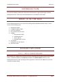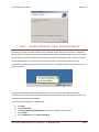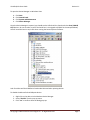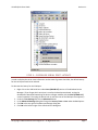
1
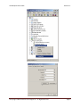
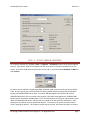
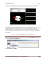
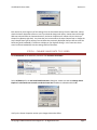
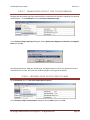
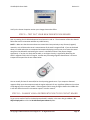
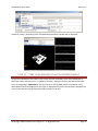
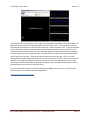
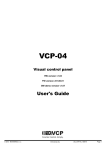
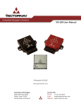
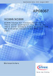
VN-100 Quick Start Guide
Version 1.1
VN-100 DEVELOPMENT KIT
QUICK START GUIDE
©Copyright 2009 VectorNav Technologies LLC. All Rights Reserved.
Page 1
VN-100 Quick Start Guide
Version 1.1
INTRODUCTION
This Quick Start Guide provides basic information and instructions to get started using the VN-100
Development board. Please refer to the Development Kit User Guide for more details.
WHAT IS IN THE BOX
The VN-100 Development Kit is a starter kit for working with the VN-100 orientation sensor. The kit
consists of the following items:
1.
2.
3.
4.
5.
Development board
5V Regulated power supply
One 6-foot USB cable
One 6-foot RS-232 serial cable
CD-ROM
a. Documentation (PDF)
b. USB Device Drivers
c. Sensor Explorer
d. Docklight Serial Terminal
6. User Manual
7. Development Kit User Manual
8. Quick Start Guide
SENSOR EXPLORER
STEP 1 – INSTALL SENSOR EXPLORER
Sensor Explorer is a graphical user interface to assist in visualizing the orientation output of the VN-100
sensor. To install the software run setup.exe provided in the /Sensor Explorer directory on the
Development Board CD. After accepting the EULA agreement, continue to click Next until you see the
installation complete dialog.
©Copyright 2009 VectorNav Technologies LLC. All Rights Reserved.
Page 2
VN-100 Quick Start Guide
Version 1.1
STEP 2 – DISABLE MICROSOFT SERIAL BALLPOINT MOUSE
Connect your version of the VN-100 DEV to the computer using either the serial cable or a USB cable,
both provided. If using the serial cable remember to power the VN-100 DEV using the 5 V power supply.
An issue exists with Microsoft XP/Vista and how they handle the USB device driver. After installing the
correct USB device driver, XP and Vista will sometimes install a second incorrect device driver.
If you see the following information box shown below then you MUST disable the mouse driver prior to
using the VN-100.
During the install of the Microsoft Serial Ballpoint your current mouse may appear to become
unresponsive for 15-60 seconds as Windows adds a new mouse driver. After you regain control of your
mouse go to Windows Device Manager.
To open the Device Manager on Windows XP:
1.
2.
3.
4.
5.
Click Start
Click Control Panel
Click Performance and Maintenance (this step is skipped in “Classic View”)
Click System
On the Hardware tab, click Device Manager.
©Copyright 2009 VectorNav Technologies LLC. All Rights Reserved.
Page 3
VN-100 Quick Start Guide
Version 1.1
To open the Device Manager on Windows Vista:
1.
2.
3.
4.
Click Start
Click Control Panel
Click System and Maintenance
Click Device Manager.
Once the Device Manager is opened, you should see the USB Serial Port listed under the Ports (COM &
LPT) devices. Be sure to make a note of the Serial Port it is assigned to (COM15 in the example below).
You will need this later in step 3 & 4 when running the Sensor Explorer software.
Look for a Microsoft Serial BallPoint listed under Mice and other pointing devices.
To disable the Microsoft Serial Ballpoint device:
1. Right click on the device in the Windows Device Manager.
2. Select “Disable” from the pop-up menu.
3. Click “Yes” to confirm when the dialog pops up.
©Copyright 2009 VectorNav Technologies LLC. All Rights Reserved.
Page 4
VN-100 Quick Start Guide
Version 1.1
STEP 3 – DECREASE SERIAL PORT LATENCY
In order to display the sensor state information at data rates of greater than 50Hz, the default latency
for the serial port needs to be reduced.
To decrease the latency for the COM port:
1. Right click on the USB Serial Port under Ports (COM & LPT) section of the Windows Device
Manager. (If you forgot which serial port is used by the development board, unplug the
development board while watching the device manager window with the Ports (COM & LPT)
section expanded. Then plug the device back in and take note of the COM port that appears.)
2. Under the Port Settings tab click the Advanced button.
3. In the Advanced Settings dialog box Change the Latency Timer to 1ms under the BM Options.
4. Click OK at the top right of the Advanced Settings dialog box.
5. Click OK at the bottom right of the USB Serial Port dialog box.
©Copyright 2009 VectorNav Technologies LLC. All Rights Reserved.
Page 5
VN-100 Quick Start Guide
©Copyright 2009 VectorNav Technologies LLC. All Rights Reserved.
Version 1.1
Page 6
VN-100 Quick Start Guide
Version 1.1
STEP 4 – START SENSOR EXPLORER
To run Sensor Explorer run navigate to Start -> Programs -> VectorNav and click on the Sensor Explorer
shortcut. After Sensor Explorer has loaded it will ask you to select a COM port and baud rate for the
sensor. Choose the COM port found previously in Step 2 & 3. Select the default Baud Rate of 9600 and
click Connect.
To ensure that the VN-100 is outputting at 9600, the board needs to be returned to its factory default
state. At any time the chip can be returned to its factory default state by resetting the VN-100 while
holding the TARE/RESTORE button down. On the VN-100 development board press and hold the
TARE/RESTORE button (the one closest to the jumpers), then while holding down the TARE/RESTORE
button tap the reset button (middle button). This can easily be done by using your right thumb to press
down the TARE/RESTORE button, and then roll your thumb to the left to tap the reset button. After
tapping the reset button you can release both buttons. The eraser tip of a pencil also works well to
assist in tapping the buttons. This sequence, performed at any time, will restore the chip to its factory
©Copyright 2009 VectorNav Technologies LLC. All Rights Reserved.
Page 7
VN-100 Quick Start Guide
Version 1.1
default settings. A 3D cube should now be visible on the screen and its orientation should track the
orientation of the VN-100 development board. Move the board around to verify its operation.
The default parameters for the VN-100 chip are 9600 baud, with Yaw/Pitch/Roll output at 10Hz. At 10Hz
the motion is choppy when displayed on the screen, so it is recommended that you display the
orientation with an output rate of at least 50Hz. As you increase the data output rate or number of
output states keep in mind that you will also need to increase the baud rate so that you have sufficient
data bandwidth.
STEP 5 – CASE OF INSUFFICIENT BANDWIDTH
First as an example, try directly increasing the output rate to 50Hz. Go to Commands on the Menu bar,
and then click Set Async Output Data Rate.
In the drop down box select 50Hz.
©Copyright 2009 VectorNav Technologies LLC. All Rights Reserved.
Page 8
VN-100 Quick Start Guide
Version 1.1
Each time that you change any of the settings from the Commands section from the Menu bar, always
check the Sensor Properties section to see if your desired change took effect. Notice that even though
50Hz was selected from the Command section, the Sensor Properties still reflects 10 Hz in the Async
Output Freq (bottom right box). Any time that you increase either the Async Output Freq or change the
Async Output Data Type to output more variables than previously displayed always make sure that the
baud rate (serial bandwidth) is sufficient to display at your desired settings. In this case since there
wasn’t sufficient bandwidth, thus the settings did not take effect.
STEP 6 - CHANGE BAUD RATE TO 115200
Go to Commands on the Menu bar, and then click Set Device Serial Rate.
Select 115200 baud in the Set Serial Baud Parameters dialog box. Make sure that the Change Sensor
Explorer’s serial baud rate to match new device baud rate checkbox is selected and click OK.
Verify in the Sensor Properties section your changes have taken effect.
©Copyright 2009 VectorNav Technologies LLC. All Rights Reserved.
Page 9
VN-100 Quick Start Guide
Version 1.1
STEP 7 - CHANGE DATA OUTPUT TYPE TO QUATERNION
Changing the data output type from Yaw/Pitch/Roll to Quaternion will provide a singularity-free attitude
representation. Go to Commands then click Set Async Output Data Type.
In the Set Async Output Data Type dialog box choose Quaternion, Magnetic, Acceleration, and Angular
Rates and click OK.
By selecting Quaternion, Magnetic, Acceleration, and Angular Rates it will not only display the sensor’s
orientation on the screen, but it will also enable the graphs on the right of the display.
STEP 8 – INCREASE DATA OUTPUT RATE TO 50HZ
Go to Commands then click Set Async Output Data Frequency.
In the Set Async Output Freq Parameter dialog box choose 50Hz and then click OK.
©Copyright 2009 VectorNav Technologies LLC. All Rights Reserved.
Page 10
VN-100 Quick Start Guide
Version 1.1
Verify in the Sensor Properties section your changes have taken effect.
STEP 9 – TEST OUT YOUR NEW ORIENTATION SENSOR
Now try rotating the VN-100 development board around in mid-air. The orientation of the cube should
follow the sensor’s orientation without any visible latency.
NOTE – Make sure that the sensor does not come within close proximity to any ferrous (magnetic)
materials, as it will distort the sensor’s measurement of the earth’s magnetic field. If you set the board
down on a table and notice an unexpected orientation displaying on the screen, then move the sensor
away from the table while maintaining the sensor’s orientation and see if the output changes
significantly. If so then it is likely that the table, or an object close by, is significantly distorting the
earth’s magnetic field in this local region. Another way of locating magnetic disturbances is to use an
inexpensive compass like the one shown below.
You can usually find one for around $10 at a local sporting goods store. If you suspect a distorted
magnetic field, move the compass around the region and watch for any significant deflection (more than
a few degrees) of the compass needle. If the magnetic field is strong enough to deflect the needle then
it will also affect the sensor’s orientation output in a similar manner.
STEP 10 – CHANGE VISUAL REPRESENTATION TO 3D CIRCUIT BOARD
To get a more realistic feel for the development board’s attitude, in the menu bar go to View -> 3D
Object Displayed then click the VN-100 Development Board option.
©Copyright 2009 VectorNav Technologies LLC. All Rights Reserved.
Page 11
VN-100 Quick Start Guide
Version 1.1
Instead of a cube, a 3D drawing of the VN-100 Development Board should now be displayed.
STEP 11 – TARE YOUR SENSOR TO MATCH SCREEN DISPLAY
To have the orientation of the model on the screen track the orientation of the actual development
board you need to tare the sensor in a specific orientation. Place the sensor on the table and tare the
sensor by navigating to Commands on the menu bar then clicking Tare. Note the orientation of the
development board now displayed on the screen. It displayed with the circuit board plane perpendicular
to the screen with the chip on top and the USB connector to the left.
©Copyright 2009 VectorNav Technologies LLC. All Rights Reserved.
Page 12
VN-100 Quick Start Guide
Version 1.1
To get a better feel for perspective, tilt the edge of the development board with the 20-pin header on it
down and note the orientation of the development board on the screen. The development board on
the 3D display will always go to this orientation whenever a TARE command is sent. To get the 3D board
to track the actual board you need to hold the actual development board so that you see it from the
same perspective as shown above, that is the VectorNav logo should be facing towards the ceiling and
your line of sight should be straight down the circuit board with the USB connector on the left and the
serial connector on the right. This may take several attempts to get it just right. Also try to avoid
moving the development board any closer than one foot from your PC monitor. Most PC monitors (LCD
and CRT) create significant magnetic distortion at a distance closer than approximately 1 foot. After
performing a TARE command with the development board in the orientation described above, the 3D
board should track the motion of the actual board.
For more information on how to use Sensor Explorer go to Help on the menu bar. You can also find
video tutorials on our website at the following address.
http://www.vectornav.com/support
©Copyright 2009 VectorNav Technologies LLC. All Rights Reserved.
Page 13