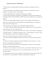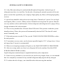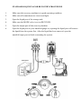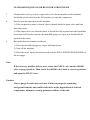
1
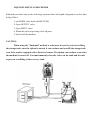
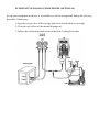
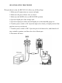
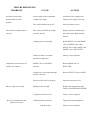
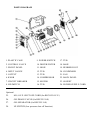
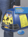
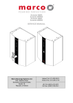
USER MANUAL
REFRIGERANT RECOVERY UNIT
RECO25 SERIES
TABLE OF CONTENTS
GENERAL SAFETY GUIDELINES ........................................
2
SPECIFICATIONS ....................................................................
4
STANDARD LIQUID/VAPOR RECOVERY PROCEDURE .
5
SELF-PURGE PROCEDURE ...................................................
7
LIQUID PUSH/PULL PROCEDURE........................................
8
TANK COOLING PROCEDURE (OPTIONAL) .....................
9
ALTERNATIVE COOLING PROCEDURE(OPTIONAL) .....
10
OIL SEPARATING PROCEDURE ..........................................
11
TROUBLESHOOTING..............................................................
12
WIRING DIAGRAM .................................................................
13
PARTS DIAGRAM ...................................................................
14
GENERAL SAFETY GUIDELINES
1. Read all safety, operating guidelines and instructions before operating this recovery
machine.
2. Always think before acting, familiarity breeds carelessness, and carelessness can be
harmful to your health, or worse, result in death.
3. Only a qualified technician should operate this Recovery machine.
4. Read all safety information regarding the safe handling of refrigerant and refrigerant oil,
including the Material Safety Data Sheet. MSDS sheets can be obtained from your refrigerant
supplier.
5. Always wear safety goggles and protective gloves when working with refrigerants to
protect your skins and eyes from refrigerant gases and refrigerant liquid. Avoid getting in
touch with causticity liquid or gas.
6. Be sure that any room where you are working is thoroughly ventilated.
7. Use ONLY authorized refillable refrigerant tanks. It requires the use of recovering tanks
with a minimum of 27.6 bar working pressure.
8. Do not overfill the storage tank. Tank is full at 80% volume. There should be enough space
for liquid expansion—overfilling of the tank may cause a violent explosion. A scale or a 80%
O.F.P. Kit must be used to avoid over filling the storage tank.
9. Do not exceed the working pressure of Recovering Tank cylinder.
10. Do not mix different refrigerants together in one tank, or they could not be separated or
used.
11. Before recovering the refrigerant, the tank should achieve the vacuum level: -0.1 mpa,
which is for purging non-condensable gases.
Each tank was full of nitrogen when it was manufactured in the factory, thus the nitrogen
should be evacuated before the first use.
12. When the recovery machine is not used, all the valves should be closed. Because the air or
the moisture of the air may harm the recovery result and shorten the service life of the
recovery machine.
13. When using an extension cord, it should be a 14AWG minimum and no longer than 7.62
meters (25feet), or it may make the voltage drop and damage the compressor.
GENERAL SAFETY GUIDELINES
14. A dry filter must always be used and should replaced frequently. And each type of
refrigerant must have its own filter. For the sake of assuring the normal operation of the unit,
please use the filter specified by our company. High quality dry filters will bring high quality
services.
15. Special care should be taken when recovering from a "burned-out" system. Use two high
acid capacity filters, in series. When you have finished recovering from the system, flush the
recovery machine with a small amount of clean refrigerant and refrigerant oil to purge off any
foreign substances left in the machine.
16. This recovery machine has a Pressure Shut Off Switch. If the pressure inside the system
should go above 38bars, the system will automatically shut itself off. The shut off switch
must be manually reset.
17. If the tank pressure exceeds 20.7bar, use the TANK COOLING PROCEDURE to reduce
the tank pressure.
18. To maximize recovery rates, use the shortest possible length of 3/8" or larger hose. A hose
no longer than 0.9 meter is recommended.
19. When recovering large amounts of liquid, use the LIQUID PUSH/PULL PROCEDURE.
20. After recovering, make sure there's no refrigerant left in the machine. Read the SELFPURGING PROCEDURE carefully.
Liquid refrigerant remained may be expanded and destroy the components.
21. If this recovery machine is to be stored or not used for any length of time, we recommend
that it be completely evacuated of any residual refrigerant and purged with dry nitrogen.
22. To reduce the risk of injury, care should be taken when moving this machine.
SPECIFICATIONS
Refrigerants
Cat. III: R-12, R-134a, R-401C, R-406A, R-500
Cat. IV: R-22, R-401A, R-401B, R-402B, R-407C, R-407D, R-408A,
R-409A, R-411A, R-411B, R-412A, R-502, R-509
Cat. V: R-402A, R-404A, R-407A, R-407B, R-410A, R-507
Voltage
220-240VAC 50/60Hz
110-127VAC 60Hz
100VAC 50/60Hz
110/220VAC 50/60Hz
Compressor
1/2 HP Oil-less
Max current
4A @ 50Hz
HP Shut-off
38bar/550psi
Recovery Rate
8A @ 60Hz
Cat. III
Cat. IV
Cat. V
Vapor
0.23kg/min
0.25kg/min
0,26kg/min
Liquid
1.57kg/min
1.81kg/min
1.85kg/min
Push/Pull
4.64kg/min
5.57kg/min
6.22kg/min
LP Shut-off
Optional
80% Capacity Shut-off Optional
Operating Temp.
0-40°C
Case
Blow Molded High Impact Polyethylene
Dimensions
19.1” L x 8.7” W x 14.4" H (485mm x 220mm x 365mm)
Net Weight
33 lbs (15kg)
STANDARD LIQUID/VAPOR RECOVERY PROCEDURE
1.
Make sure this recovery machine is in good operating condition.
2.
Make sure all connections are correct and tight.
3.
Open the liquid port of the storage tank.
4.
Make sure the MODE valve is set on RECOVER.
5.
Open the output port of the recovery machine.
6.
Open the liquid port on your manifold gauge set; opening the liquid port will remove
the liquid from the system first. After the liquid has been removed, open the
manifold vapor port to finish evacuating the system.
STANDARD LIQUID/VAPOR RECOVERY PROCEDURE
7.
Connect the recovery unit to a right outlet. (See the nameplate on the machine)
Switch the power switch to the ON position, to start the compressor.
8.
Slowly open the input port on the machine.
1) If the compressor starts to knock, slowly throttle back the input valve until the
knocking stops.
2) If the input valve was throttled back, it should be fully opened once the liquid has
been removed from the system (the manifold gauge set vapor port should also be
opened at this time).
9.
Run until desired vacuum is achieved.
1) Close the manifold gauge sets vapor and liquid ports.
2) Turn off the machine.
3) Close the unit's input port and proceed with the SELF-PURGE PROCEDURE on
the next page.
Note:
If the recovery machine fails to start, rotate the INPUT valve and the MODE
valve to purge position. Then rotate the MODE valve back to recovery position,
and open the INPUT valve.
Caution:
Always purge the unit after each use. Failure to purge the remaining
refrigerant from the unit could result in the acidic degradation of internal
components, ultimately causing premature failure of the unit.
SELF-PURGING PROCEDURE
Procedure for purging remaining refrigerant from this machine.
1. Close the ports of the system being serviced that are connected to the input port of
the machine.
2. Turn off the recovery machine.
3. Turn the Input valve to the PURGE position.
4. Turn the MODE valve to the PURGE position.
5. Restart the machine.
6. Run until desired vacuum is achieved.
7. Close the ports on the recovery tank and the machine.
8. Turn the machine off.
9. Return the MODE valve to the RECOVER position.
10. Disconnect and store all hoses and dry filter.
LIQUID PUSH/PULL PROCEDURE
Push/pull procedure only works with large systems where the liquid refrigerant is no less than
6.8kg (15lbs.).
1. put MODE valve knob on RECOVER.
2. Open OUTPUT valve.
3. Open INPUT valve.
4. When the scale stops rising close all ports.
5. Switch off the machine.
CAUTION:
When using the "Push/pull" method, a scale must be used to avoid over filling
the storage tank, once the siphon is started, it can continue and overfill the storage tank
even if the tank is equipped with a float level sensor. The siphon can continue even when
the machine is turned off. You must manually close the valves on the tank and the unit
to prevent overfilling of the recovery tank.
TANK COOLING PROCEDURE (OPTIONAL)
In order for this procedure, you must have a minimum of 5 lbs. (2.3kg) of liquid refrigerant in
the storage tank.
1. Connect the hoses as shown
2. Turn the MODE valve to the Recover position.
3. Open the Vapor and Liquid valve of the storage tank.
4. Power on, and start the compressor.
5. Open the INPUT valve and OUTPUT valve of the machine.
6. Throttle the OUTPUT valve of the machine so that the output pressure is 100psi
greater than the input pressure, but never more than 300psi.
7. Run until tank is cold.
ALTERNATIVE/COOLING PROCEDURE (OPTIONAL)
Set up your equipment as shown, it is possible to cool the storage tank during the recovery
procedure if necessary.
1. Open the vapor valve of the storage tank (it is closed while recovering).
2. Close the two valves of the manifold gauge set.
3. Follow the sixth and seventh items of the tank Cooling Procedure.
OIL SEPARATING PROCEDURE
This procedure is only for RECO25 O.S. (Recovery & Recycling)
1. Make sure all connections are correct and tight.
2. Make sure the port of drain valve is closed.
3. Make sure the MODE valve on RECOVERY position.
4. Open the liquid port of the storage tank.
5. Open the output port of the unit and liquid port on the manifold gauge set.
6. Turn the power switch to ON. Open the input valve slowly to liquid position. Run
until the recovery is achieved.
7. Turn the power switch to OFF. Open the port of oil drain valve, and drain the oil
into a suitable container, and then close the oil drain port.
8. Disconnect all hoses.
TROUBLESHOOTING
PROBLEM
CAUSE
ACTION
Fan does not run when
Power supply cord not attached
Attach the power supply cord.
Power Switch is in ON
voltage is not right
Check power supply at job site.
The circuit breaker has cut off
Press the button to reset
Fan runs but compressor does
The recovery machine is in high
Reduce pressure and then press
not start
pressure shut off
the button of the High Pressure
position
Switch.
Output pressure is too high
Rotate INPUT valve and MODE
valve to PURGE, then rotate
INPUT valve back to OPEN, and
MODE valve to RECOVER
Failure in motor, or in other
Factory service required
electrical components.
Compressor starts but cuts off
MODE valve is in PURGE
Rotate MODE valve to
within a few minutes
position
RECOVER
Output valve is not open and high
Rotate OUTPUT valve to OPEN
pressure activates
Recovery process too slow
Recovery tank valve is not open
Open recovery tank valve
Head pressure too high
Reduce tank temperature with
TANK COOLING PROCEDURE
Recovery machine does not
Compressor seals are worn
Factory service required
Connecting hoses are loose
Tighten the connecting hoses
pull out a vacuum
Leakage in unit
Factory service required
WIRING DIAGRAM
Wiring Diagram --- Standard
Wiring Diagram --- Low pressure shut off function
PARTS DIAGRAM
1. PLASTIC CASE
9. POWER SWITCH
17. TUB
2. CONTROL VALVE
10. DRYER/FILTER
18. BASE
3. FRONT PANEL
11. HOSE
19. RUBBER FOOT
4. INPUT GAUGE
12. TUB
20. CONDENSER
5. OUTPUT
13. TUB
21. FAN
6. KNOB
14. COMPRESSOR
22. BACK PANEL
7. CIRCUIT BREAKER
15. MOTOR
23. SOCKET
8. HP SWITCH
16. TUB
24. POWER SUPPLY CORD
Optional
25.
80% O.F.P. SHUT OFF CORD (for RECO25 O.F.P.)
26.
OIL DRAIN VALVE (for RECO25 O.S)
27.
OIL SEPARATOR (for RECO25 O.S)
28.
LP SWITCH (low pressure shut off function)