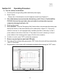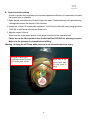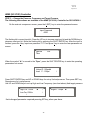
1
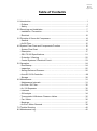
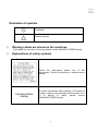
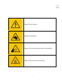
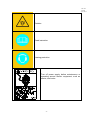
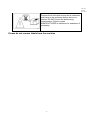
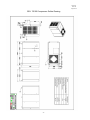
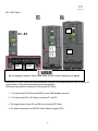
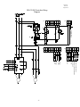
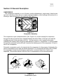
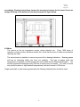
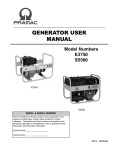
CAP-876 REV. H April, 2014 GSV Series OIL-INJECTED ROTARY SCREW COMPRESSORS OPERATOR MANUAL GSV-75 GSV-100 CAP-876 REV.H April, 2014 Table of Contents 1.0 Introduction ..................................................................................................... 1 - Preface .......................................................................................................... 1 - Safety ............................................................................................................ 5 2.0 Receiving and Installation ............................................................................... 7 - Installation / Precaution.................................................................................. 9 - Electrical ...................................................................................................... 10 3.0 Principle of Screw Air Compressor ................................................................ 14 - General ........................................................................................................ 14 - Air/Oil Flow................................................................................................... 15 4.0 System Flow Chart and Components Function ............................................. 16 - System Flow Chart ...................................................................................... 16 - Description ................................................................................................... 17 - GSV-75/100 Specifications .......................................................................... 21 - Protection / Warning .................................................................................... 22 - Control Systems / Electrical Circuit .............................................................. 23 5.0 Operation ...................................................................................................... 24 - Run/Startup…………………………………………………………… ............... 24 - Inspection .................................................................................................... 25 - Setting Delivered Pressure ……………………………………… .................... 26 - Aims SC-2100 Controller ………………………………………………………...28 - Storage ........................................................................................................ 30 6.0 Maintenance.................................................................................................. 31 - Maintenance Intervals .................................................................................. 31 - Air Filter / Oil Filter ....................................................................................... 32 - Air / Oil Separator ........................................................................................ 32 - Lubricant ...................................................................................................... 33 - Oil Analysis .................................................................................................. 34 - Thermostatic & Minimum Pressure Valves................................................... 35 - Fan / Motor .................................................................................................. 36 - Bearings....................................................................................................... 37 - Air End / Motor Removal .............................................................................. 38 7.0 Trouble Shooting ......................................................................................... 40 8.0 Maintenance Log........................................................................................... 42 CAP-876 REV.H April, 2014 Chapter 1.0 Introduction A. Preface Warning Read this manual before installation and operation. Become familiar with this manual, its safety instructions and its operation before beginning any work. Serious personal injury may result if safety or operational information is not understood. ◎ Alert signals Description of signals △ ! Danger △ ! Warning △ ! Danger is used to indicate presence of a hazard that will cause severe personal injury or death, or substantial property damage. Warning is used to indicate the presence of a hazard, which can cause severe personal injury, or substantial property damage. Caution is used to indicate the presence of a hazard, which can cause personal injury, or property damage. Caution _ ____ _ ____ _ ____ Supplementary instruction for operation and maintenance Reference -1- CAP-876 REV.H April, 2014 Illustration of symbols Prohibited Extreme caution ◎ Warning Labels are placed on the machines. If the labels are not clear or missing, please contact MANUFACTURER directly. ◎ Explanations of safety symbols Operation manual Follow the instructions before use of this compressor. Confirm the direction of rotation before startup. Caution before startup To restart compressor after inactivity of 6 months or longer, rotate air end manually with the power off. If it is difficult to rotate, please contact MANUFACTURER directly. -2- CAP-876 REV.H April, 2014 Danger: Electric circuits Danger: Rotating parts Danger: Hot or noxious gases outlet: unbreathable Danger: Heat. Do not touch hot areas -3- CAP-876 REV.H April, 2014 Rotation Read instruction Hearing protection Turn off power supply before maintenance or operating around electric equipment, such as starter, and motor. -4- CAP-876 REV.H April, 2014 Remove the 4 bolts that secure the air end/motor sub frame to the enclosure before test run or startup. DO NOT loosen the bolts during transportation. Please contact MANUFACTURER or distributor for assistance if necessary. Please do not remove labels from the machine -5- CAP-876 REV.H April, 2014 Safety 1. Become familiar with this manual and follow the instructions before operating the compressor. 2. If any malfunctions or trouble occurs, do not run compressor until problem is resolved. 3. Make sure the compressor has been disconnected before servicing or changing parts. Lockout and tagout prior to maintenance. 4. To ensure human safety and protect the facility from damage, do NOT ignore electrical grounding. 5. Wear proper apparel during operation. Protective clothing should be worn such as facemask or safety goggles and non-slip footwear. -5- CAP-876 REV. H April, 2014 Additional Safety information for Air Compressors Like all power tools, there is danger associated with operating this equipment. Accidents are frequently caused by lack of familiarity or failure to pay attention. Use this machine with extreme caution. If normal safety precautions are overlooked or ignored, serious personal injury may occur. The following are some safety suggestions that users should be familiar with: Caution ·Users who neglect these safety precautions run the risk of serious injury or death. ·Keep fingers and clothing far away from rotating parts. ·Compressed air from this machine cannot be used for pharmaceutical, food, breathing air or health requirements without further treatment. ·Release all pressure from the system prior to maintenance. ·Electric shock could be fatal. ·Grounding of starter and motor is necessary. Choose grounding cable according to the power range of the compressor. ·Ground fan motor through starter. ·Lockout and tagout power supply before working on control panel. ·Lockout and tagout power supply before inspection and maintenance -Compressor is controlled by PID (proportional integral derivative) controller and may start automatically according to the setting. PID is a generic control loop feedback controller widely used in industrial control systems. Warning Users who neglect the following instructions might damage the compressor. ·Lockout and tagout the compressor if maintenance is needed. ·Lockout and tagout power supply before inspection and maintenance -Compressor Is controlled by PID (see above) and may start automatically according to the setting. ·Relief valve is necessary for air piping larger than 1/2”. ·Do not exceed the rated discharge pressure on nameplate during operation. ·The enclosure should be in place prior to operation -6- CAP-876 REV. H April, 2014 Section 2.0 Receiving and Installation A. Receiving 1. Check your order to ensure it is correct. 2. Check if the machine or any accessories received any damage during shipment. 3. Upon receiving this machine, please read this manual thoroughly and any supplements related to the equipment you purchased before attempting to install or operate the compressor. B. Installation In order to ensure proper installation and trouble free operation: 1. The compressor should be installed on any level surface capable of supporting its weight. 2. Lift the compressor using the area under the base frame. Make sure the lift equipment has enough capacity and complies with local regulation. 3. Select a location that is dry, well ventilated, and where the atmosphere is as clean as possible. The area should be free of dust, chemicals, metal filings, paint fumes and overspray. 4. The ambient temperature should be kept below 104ºF and above 32℉. 5. See general arrangement drawing for minimum space requirements, for normal operation and maintenance. 6. Hard surfaces may reflect noise with an apparent increase in decibel level. If sound transmission is important, install a sheet of rubber or cork beneath the compressor to reduce noise. Flexible piping may be required. 7. It is recommended that there be at least 38” of clearance between top of compressor and overhead air duct installation for better cooling effect on air-cooled compressors. Mounting nuts on air inlet and outlet are prefabricated on cabinet. 8. Remove the 4 bolts and red blocks that secure the air end/motor sub frame for shipment to the enclosure before test run or startup. See diagram below. Mounting bolt Red block -7- CAP-876 REV. H April, 2014 GSV- 75/100 Compressor Outline Drawing -8- CAP-876 REV. H April, 2014 Recommendations & Precautions for Air Piping and Cooling System 1. Air Piping (1). Install required accessories. (2). Main piping should have 1˚- 2˚ slant away from the compressor to drain the condensate. (3). Pressure drop of piping must not exceed 5% of discharge pressure. Select larger piping than required for better efficiency. (4). Branch line must be located at the topside of main piping to avoid condensate from flowing into the facilities. (5). To prolong service life of pneumatic tools, install an air filter regulator unit on the outlet. (6). Do not randomly reduce the size of the main piping. If necessary, use the proper reducer or a large pressure loss may incur . (7). The common installation arrangement is; air compressor + air tank + dryer. An air tank is capable of draining some of the condensate and cooling down the temperature of compressed air. This will lead to more efficient dryer operation. (8). If the air requirement is large for a short period, install a higher volume air tank to reduce the frequency of full/off load control. (9). The ideal piping main would be constructed around the factory as a loop for delivering compressed air from both sides at any point. 2. Cooling System Install the air-cooled compressor in a well-ventilated area to avoid high temperature shutdown. If the unit is in a sealed room, ventilation is required and its capacity must be larger than the cooling fan in the compressor. In accordance with (Figure: 2-1) please select proper ventilating equipment for use. Figure: 2-1 Model GSV-75 GSV-100 HP 75 100 Heating Btu 225400 307500 Volume of Ventilating Volume of Ventilating Fan Compressor Room cfm cfm 7600 >12000 7600 >12000 Remarks: The above data is compressor room temperature rise according to design by atmospheric temperature. Electrical -9- CAP-876 REV. H April, 2014 It is recommended that a qualified electrician in compliance with standards and local codes do all electrical wiring. Be sure to investigate the local requirements before installing the compressor. Refer to the wiring diagram before starting any work. The power supply should be adequate and free of parasitic loads that will cause an under voltage condition during the operation of the compressor, otherwise there will be nuisance electrical shutdowns. This equipment requires a properly grounded electrical disconnect switch. We recommend the use of time delay fuses in a fusible disconnect for isolating the unit. This disconnect should be located so an operator can disconnect the unit without being near the unit in case of an emergency. We also recommend the use of a lockout/tagout to help insure safety during maintenance of the compressor. Per the National Electric Code the time delay fuses should be sized at 175% of the full load amperage (FLA) found on the motor nameplate. Consult the Code if you want to use another style of branch circuit protection. Failure to properly ground compressor package could result in controller malfunction. Figure 2-2 Chart of Unit Amp Draw Model Number GSV-75 GSV-100 HP 75 100 460Volts 132 Amps 187 Amps Before applying power necessary to determine what type of network the drive will be connected to. How to determine the type of grounding system - 10 - CAP-876 REV. H April, 2014 Four measurements are required: 1. Input voltage line to line 2. Input voltage line 1 to ground 3. Input voltage line 2 to ground 4. Input voltage line 3 to ground Four simple measurements will help determine the network grounding you are connected to. These readings should be taken from the line side of the circuit breaker or disconnect before power is applied to the drive. Readings (2), (3), and (4) are divided by reading (1) to establish a ratio. The resulting ratios are then compared to the table values to determine which grounding type is present. In the “ungrounded/floating instance” the determining factor is not the ratios present but rather the variability and randomness of readings (2), (3), and (4). - 11 - CAP-876 REV. H April, 2014 RFI / EMC Filters F2 R1…R4 F1 EM1 EM3 Do not attempt to install or remove EM1, EM3, F1 or F2 screws while power is applied Ensure the RFI/EMC filters are disconnected as required for floating networks, also known as IT, ungrounded, or impedance/resistance grounded networks: Disconnect the ground connection to the internal RFI filters: 1. For frame sizes R4: Remove the EM1 screw, EM3 already removed. 2. For frame sizes R5 to R6: Remove screws F1 and F2. The larger drives, frame R7 and R8 do not include RFI filters. For detail information use ACS550 User’s Manual (page 20-21) - 12 - CAP-876 REV. H April, 2014 GSV-75/100 Controller Wiring Diagram XGD 1 ACIN2 2 ACIN3 3 Controller Power 24VDC DI4 DI3 DI2 DI1 DI0 7 6 5 4 3 2 1 E-STOP DRIVE FAULT ACIN0 1 TIN- PIN- 5 4 3 OL + - Pt100 T Input P Input 4~20mA RS485 SUCTION FILTER MONITORING FAN MOTOR OVERLOAD GND 8 ACIN1 2 TIN- 21 A 22 B 3 TIN+ 7 1 4 I1 8 2 KF 5 I2 9 PIN+ RCS 6 FIR SV KS 7 - - JP1 GND 11 6 RCD 10 B FIT R JP4 VST A2 8 A1 KD 14 9 13 KM - 13 - JP5 JP3 + - CAP-876 REV. H April, 2014 Section 3.0 General Description COMPRESSOR The compressor assembly is an oil flooded, positive displacement, single stage, helical screw type unit consisting of two rotors or screws supported axially by roller bearings and enclosed in a housing or stator as depicted in the sectional view Figure 3-1. Figure 3-1 Compressor Assembly The compression cycle as depicted below, (Ref. Figure 3-2), has air entering the compressor through the inlet port that becomes trapped between the helical lobes of the main rotor and the matching grooves of the secondary rotor (A). As the rotors turn, air is trapped in the cavity created by the mashing lobe and groove and reduced in volume or “compressed”. It is then pushed through the successive cavities (B) until it reaches the discharge end of the compressor (C) and is sent to the oil separator. During the compression cycle, oil is injected into the compressor for the purpose of dissipating the heat of compression and to seal the internal clearances. The compressed air laden with oil leaves the compressor through the discharge port and enters a reservoir where the oil and air are separated. This process delivers a smooth flow of compressed air at the desired pressure. INLET SECONDARY ROTOR MAIN ROTOR A B C Figure 3-2 Compression Cycle - 14 - DISCHARGE CAP-876 REV. H April, 2014 AIR/OIL FLOW Air enters the compressor through the air filter, inlet valve and compression chamber where it is mixed with oil. After compression, the air/oil mixture is discharged into the oil separator where its velocity is reduced causing most of the oil to drop to the bottom. The remaining oil is removed as the air passes through the separator element. Oil collected at the bottom of the separator element is returned to compression chamber through the scavenge line. The compressed air that is saturated with oil then passes through the minimum pressure valve set to maintain a minimum of 65 psi in the oil separator to ensure a sufficient flow of oil to the compressor. The compressed air then enters the aftercooler where it is cooled and discharged to its point of usage. A sufficient amount of oil is stored in the oil separator tank and is forced by the pressure of compression from the separator to the thermal by-pass valve. The thermal by-pass valve regulates the flow into the oil cooler depending on the temperature of the oil. The thermal by-pass valve will open when the oil reaches a predetermined temperature allowing the hot oil to enter the cooler. Oil which has not reached this temperature setting will by-pass the cooler. The oil is then filtered and sent to the compressor to initiate the compression cycle. The oil also serves as lubrication for the compressor bearings. - 15 - CAP-876 REV. H April, 2014 Section 4.0 System flow chart and components function A. System flow chart and component function GSV 75-100 System Flow Chart 1 Air intake filter 14 Check Valve 2 Intake valve 15 Pressure Sensor 3 Air end 16 Air intake filter ΔP switch 4 Discharge Tube 17 Pressure Sensor 5 Air/Oil Separator Vessel 18 Controller 6 Air/Oil Separator 19 Inverter 7 Safety Valve 20 Motor 8 Minimum Pressure Valve 21 Coupling 9 AfterCooler (Radiator) 22 Temperature Sensor 10 Air Outlet Valve 23 Main Fan 11 Oil Drain Valve 24 Oil Level Gauge 12 Thermostatic Valve 25 Inlet control module 13 Oil Filter 26 - 16 - CAP-876 REV. H April, 2014 B. Description of system flow chart and component function 1. Air flow path (refer to the flowchart) 1.1. After dust is removed by the intake filter, clean air goes through the intake valve into the compression chamber and is mixed with oil. The mixture is compressed and delivered through the oil separator, minimum pressure valve and after cooler. 1.2. Function of parts in the air flow path (1). Air intake filter The air intake filter is a suction filter which is a special-purpose air cleaner for the air compressor. For normal environmental use, clean the dust on the element from inside out with low regulated compressed air every 1,000 hours of operation. The air filter LED lamp “on” indicates that the filter needs to be cleaned or replaced. Replace the filter at the recommended interval for your application. (2). Intake Valve The check valve of the intake valve is opened during startup. As a result, the system pressure gradually increases. After the compressor is loaded, the frequency converter will adjust the motor rotational speed to maintain the system pressure. When the air demand is lower than the air supplied, the system pressure will reach the unload setting value. The compressor then runs in shutdown mode. When the system pressure reaches the load setting value, the compressor ramps up to meet demand. (3). Temperature Sensor The Temperature Sensor sends a signal and displays oil temperature on the control panel. Its normal setting is 230℉. Lack of oil circulation or a dirty cooler will induce high discharge temperature. Do not operate over this temperature, otherwise the compressor may be damaged and trip. (4). Air/Oil Separator Vessel There is an oil level gauge at the bottom of the air/oil separator vessel. Maintain the oil level in the green range. On the bottom of the tank there is a drain valve. Remember to drain condensate water every time before startup. In addition, an oil fill cap for oil replacement is located near the bottom of the tank. Add oil only when the oil level is in the red range on the gauge as read when the compressor is on. Drain oil only if the oil level is in the yellow range on the gauge (overfill) as read when the compressor is on. (5). Air/Oil Separator Element Please refer to the description on oil flow path. (6). Minimum Pressure Valve The minimum pressure valve is located at the air discharge outlet from the oil separator. Operating pressure is set to be around 65 psi and field settings are not required. The functions of minimum pressure valve are shown below: A. Build up oil circulation pressure to lubricate the air end. B. When air pressure is over 65 psi, it will reduce the flow rate passing thru and protect air/oil separator from damage due to large pressure difference and increase oil separator efficiency. C. Prevents back flow under off load conditions. (7). After Cooler (Radiator) This is the cooler for air-cooled series compressors. The compressed air is cooled by the - 17 - CAP-876 REV. H April, 2014 fan blowing air through the radiator. Generally, discharge air temperature is 15-20℉ above ambient operating temperature. A clean and cool environment is a crucial factor for efficient and trouble free operation of an air-cooled type air compressor; please install the compressor in a well-ventilated area. 2. Oil flow path (refer to the flowchart) (1). Description of oil injected flow chart Pressure in the air/oil separator vessel pushes oil into the oil cooler. The cooled down oil passes through the oil filter for filtration. Oil flow is further separated in 2 directions; one goes into compression chamber from the bottom of the air end, and the other goes into the bearing on the discharge side for lubrication. The compressed air and oil mixture is then delivered to the air/oil separator vessel again to separate most of the oil (1st Stage) and the rest of the oil mist goes through the oil separator (2nd Stage) for further separation. Finally, compressed air passes through minimum pressure valve into the after cooler and is discharged. (2). Volume of oil injection The purpose of oil injection in the screw compressor is to dissipate the heat away from the process of air compression. Please do not adjust oil volume by the ball valve. Seek assistance from MANUFACTURER if necessary. (3). Oil flow system A. Oil Cooler The function of the oil cooler is the same as the air cooler. A clean and cool environment is a crucial factor for efficient and trouble free operation of an air-cooled type air compressor; please install the compressor in a well-ventilated area. Clean the dust on the fins of the radiator periodically with compressed air or with solvent. B. Oil Filter The oil filter takes out metals, sludge and unwanted particles from the compressor oil in order to protect bearings and rotors. Failure to replace the oil filter may result in lack of oil, which will lead to high discharge temperatures and shorter bearing life. C. Air/Oil Separator a. Function: Air/Oil separator consists of a multiple layer filtration element that provides the final removal of oil from the air stream. Oil impinging on the inside of the separator element drains directly back into the air/oil separator vessel by gravity. Oil collected outside the element is returned through tubing to the compressor cylinder. Air/Oil separator life will vary greatly depending on the conditions of operation, the quality of the oil used and the maintenance of the oil and air filters. Use CurtisLubePlus FSC-8000 in order to maintain your warranty. b. Reasons for air/oil separator replacement 1. Oil carryover increases. 2. Warning on controller indicates replacement. 3. Running current increases. 3. Cooling system Air-cooled Air is drawn in by the fan through the radiator fins and dissipates heat away from the compressed air and oil. The highest allowable temperature at the airend discharge is 230℉. - 18 - CAP-876 REV. H April, 2014 Temperatures above this will cause the compressor to shutdown. 4. Control principle for frequency speed controlled air compressors The control logic of conventional fixed speed compressors is shown in fig. 4-1. For example, the current enters the 2-pole motor with 60Hz thus the theoretical rotation speed of motor output is 3600rpm. The required rotation speed can be achieved by adjusting a pulley or gear ratio. However, the speed is still a fixed value. When the demand of compressed air at the end user decreases, the amount expelled cannot be reduced by adjusting the rotation speed of the machine itself. Therefore in most fixed speed compressors, valves, such as a suction valve, must be introduced to control the amount of air sucked in. On the other hand, the frequency controlled GSV Series compressor has an inverter installed near the motor, which is used to adjust the rotation speed of the motor as demanded. Current frequency 60Hz Frequency Converter Frequency Converter Input 1~140Hz Fixed frequency machine type Motor Rotation Speed 60~7200 RPM Fig 4-1 Besides the variable speed inverter, another characteristic of the GSV Series speed controlled air compressor is a stable and accurate feedback control system. Its basic control flow is shown in fig. 4-2. When the pressure transducer delivers the pressure value P net in the system into the controller, the controller passes the corresponding 4~20mA signal according to the pressure received to the inverter. When the value of P net is lower than the set value P setting in the inverter, this indicates that the air demand at end user is increasing, and the inverter will adjust the rotation speed of the motor in order to increase the output of the air and achieve the set value of pressure (not over the maximum set rotation speed for the air compressor). Since the demand for compressed air at the end user will change variably according to the real process requirement, the PID (proportional, integral, and differential) function of the inverter converts the amount of airflow required by controlling the motor speed in a real-time and precise mode. If it fails to perform calculations precisely, the pressure set value P net in the air receiver will change too rapidly to - 19 - CAP-876 REV. H April, 2014 stabilize the setting pressure value P compressors is within ±1.4psi. Motor setting. The variation of pressure on frequency control air Compressor 100% Pressure 100 psi 100% Control Rotation Speed 40% Pressure 103 psi 40% Frequency Inverter ΔP PID Control Demand 40% Δt P: Proportional I: Integral D: Differential Built in the frequency inverter Fig. 4-2 - 20 - CAP-876 REV. H April, 2014 5. GSV Series Screw Air Compressor Specification 1. GSV 75-100 Model GSV-75 Item System Operating Pressure Capacity Air Discharge Temp. Pressure relief valve setting Power psi 100 125 150 100 125 150 CFM 353 332 299 474 430 390 m3/min 10.5 9.9 8.9 14.1 12.8 11.6 ℉ Ambient temperature + 20° psi Setting pressure 200 psi HP kW 75 55 Dimension Motor Enclosure Main Motor Speed GSV-100 100 75 TEFC rpm 828-2544 828-2455 828-2130 740-3550 740-3195 740-2929 Starter Inverter Voltage Volt 230/460, 3PH Frequency Hz 25-120 Length in 93.9 Width in 47.6 Height in 72.6 Weight lbs 4000 inch 2” PF Discharge outlet Capacity (FAD) measured in accordance with ISO 1217, Ed 3, Attachment C 1996, Ref. condition: Dry air, suction pressure 1 bar. Due to continuous product development at FSCURTIS, design and specifications are subject to change without notice. - 21 - CAP-876 REV. H April, 2014 E Protection and warning 1. Motor overload protection There are two motors in the compressor assembly. One is the main drive motor and the other is the cooling fan motor. Generally, when running current that exceeds the upper limit of the relay, the main power will shutdown automatically. Re-setting the unit is required prior to the next startup. The relay limit has been preset by the factory. To maintain normal operation, please do not change the limit setting without consulting the factory. (1)Human error; such as adjusting to a higher discharge pressure, or improper setting of the overload relay may cause a nuisance trip. (2)Mechanical failure: A. Such as motor internal phase loss, safety valve malfunction, or improper setting, oil separator clog and/or startup with backpressure that results from a non-closed intake valve…etc. B. If motor overloads during operation, please contact manufacturer immediately to prevent damage to the motor. 2. Protection for discharge temperature Discharge temperature setting is 230 ℉ . If the temperature exceeds 230 ℉ , the compressor will trip. One of the most common reasons for high discharge temperature is an issue with the oil cooler. For an air-cooled compressor, if the radiator is clogged, the oil temperature goes up resulting in a trip condition because cooling air can’t pass through the radiator. The high discharge temperature alarm will display at 221℉. Clean the dust off the fins of the radiator periodically with compressed air or with a solvent as needed. The GSV Series air compressors are designed to operate up to 104℉ ambient temperature making it necessary to place it in a well-ventilated area. When the compressor is tripped due to a high discharge temperature, it is unable to restart unless the reset button is pressed. 3. Warning Compressor has a warning system for the air intake filter, oil filter, and oil separator. If one of these filters is clogged, the controller will show a warning. Please replace with factory parts to ensure safety and high efficiency operation. - 22 - CAP-876 REV. H April, 2014 F Control system and electrical circuit 1. Control system (a)Motor startup The intake valve gradually opens with motor startup because of the vacuum inside the compressor inlet. Oil circulating to lubricate the compression chamber and the bearing is assured by the pressure difference between the vacuum and atmosphere. (b)Motor operation After motor startup, system pressure gradually increases until the compressor is running at full load. The intake valve stays fully opened. Air is then delivered through the minimum pressure valve to the end user when pressure is at least 65.3 psi. (c)Full/off load operation When the system pressure reaches the upper limit of the settings, the intake valve closes and the air/oil separator vessel relieves the air to ambient. Compressor is then running off load. When system pressure reaches the lower limit of the setting, the intake valve opens and relief stops. The unit is then on load. (d)Stop Pressing the “OFF” button (See Aims controller manual) will close the intake valve and relive pressure in the air circuit. When pressure in the air/oil separator vessel reduces to a preset value a timer will countdown and if no air is needed then the motor will stop/shutdown. (e)Emergency stop When the emergency stop is activated, the main power supply will be shutdown with a warning shown on the control panel. Motor will stop immediately, air circuit pressure will be relieved and the intake valve will close to prevent lubricant from coming out of the air end. Only use the emergency stop button in a hazardous situation. (f)Auto stop with time lag If compressed air is not required, the compressor runs at “off load” until it is stopped after a set time lag. If compressed air is required, the compressor runs at “full load” to meet the demand. The amount of possible auto stops is limited to five times each hour. Since there is no warning on the panel for an auto stop, be careful using this function. Frequent starting and stopping of the motor will result in motor damage. - 23 - CAP-876 REV. H April, 2014 Section 5.0 Operating Procedure A Test run, startup and shutdown 1. Connect power and grounding cables and check power supply. 2. Check oil level: -Please refer to the description on air/oil separator vessel from Chapter 4-2. 3. If the initial startup is several months after delivery, add 0.5 Liter of CurtisLubePlus FSC-8000 lubricant through intake valve and rotate air end manually to prevent compressor damage from lack of oil. 4. Check cooling system 5. Check Rotation - Press the “Emergency Stop” button within a few seconds after startup and identify the direction of the airend and fan motor rotation(refer to figure 5.1). If the motor rotation is incorrect, for units equipped with a variable speed drive, switch any 2 of the 3 power cables on the bottom of the drive. If Fan rotation is incorrect, switch any 2 of the 3 power cables on the incoming power supply of the fan motor contactor. 6. If rotation is correct, press “ON” to restart the compressor. 7. Observe any warning from panel and LED lights. 8. Time delay will be activated after pressing the “OFF” button; the motor will stop automatically after 10-15 seconds. 9. Compressed air in the system will be released immediately after pressing the “OFF” button. Figure 5.1 - 24 - CAP-876 REV. H April, 2014 B Inspection before startup In order to protect the compressor and increase operational efficiency it is necessary to inspect the system prior to operation. 1. Open the ball valve below the oil tank to drain the water. Condensed water will cause bearing damage and reduce the lifespan of the lubricant. 2. Inspect the oil level 10 minutes after shutdown. The Oil level could read lower during operation. Refill the oil until arrow reaches the Green zone. 3. Maintain correct oil level: Arrow must be in the green section of the gauge mounted on the separator tank. Please do not use lubricant other than CurtisLubePlus FSC-8000 for warranty purposes. Make sure the pressure is released before refilling. Warning: Opening the oil fill cap while pressure is not released may cause injury. Fill with oil until arrow reaches the border between yellow and green regions Black line in the green region must be in the center of gauge - 25 - CAP-876 REV. H April, 2014 C During operation 1. Shutdown the compressor if abnormal noise or vibration is observed. 2. Do not loosen any screws or open any control valves during operation. Warning: Failure to do so may cause injury. 3. Make sure to drain condensed water in after cooler and water separator. 4. Record voltage current, discharge pressure, discharge temperature, and oil level. Inspect gauges periodically during operation for future reference. 5. For extreme environment application, FSCURTIS controllers are equipped with a Frost Protection function to prevent lubricant from coagulation. Please refer to controller manual page.21 for detail setting. Setting the compressor delivered pressure Observe all safety precautions and follow all safety guidelines when performing service to your air compressor. To change the pressure the compressor delivers requires five steps. These must be done in the following sequence. These first 4 steps are done on the ABB Drive keypad 1. Unlock the parameters 2. Change the Internal Setpoint pressure on the drive key pad for the desired operating pressure 3. Change the drive set Frequency to match the operating pressure in step one 4. Lock the parameters The last 3 steps are done on the AIMS Plus controller on the front of the machine 5. Change the System Safety pressure to protect against high sump pressure 6. Change the Cut-Out (Unload) pressure set point 7. Change the Cut-In (Load) pressure set point ABB Drive Key Pad STEP 1 -- Unlock the parameters 1. From the main screen on the drive keypad displaying Hz, Current and Pressure; press the arrow button under Menu. After pressing Menu the screen will display PARAMETERS. 2. With the PARAMETERS highlighted press ENTER key 3. Using the DOWN arrow key to scroll to Group 16 “System Controls”, press the SEL key and scroll down to Parameter 1603 “Pass Code”. Press the EDIT key. Using the UP arrow button set pass code 358 (hold UP button till 300 displayed, wait for 2 sec till cursor switches to tens & enter 5; wait 2 sec till cursor switches units & enter 8; press the SAVE key. 4. Using the UP arrow key to scroll to Parameter 1602 “Parameter Lock”, press the EDIT key and scroll UP changing condition from LOCKED to OPEN. Press the SAVE key. Press the EXIT key once. - 26 - CAP-876 REV. H April, 2014 STEP 2 -- Change the Reference Frequency 1. Using the DOWN arrow key to scroll to Group 11“Reference”, press the SELECT key and scroll down to Parameter 1104 “Minimum Freq” and 1105 ”Maximum Freq” Press the EDIT key to change the maximum Frequency. Using the UP or DOWN arrow button set your required frequency from the chart below. Once the frequency is selected press SAVE key & then press EXIT key once. STEP 3 -- Change the Frequency 2. Using the DOWN arrow key to scroll to Group 20 “Limits”, press the SELECT key and scroll down to Parameter 2007 “Minimum Freq” and 2008 “Maximum Freq”. Press the EDIT key to change the maximum Frequency. Using the UP or DOWN arrow button set your required frequency from the chart below. Once the frequency is selected press SAVE key & then press EXIT key once. UNIT GSV-20 GSV-25 GSV-30 GSV-40 FD SET FREQUENCY 100PSI MAX / MIN Hz 95 / 35 125PSI 89 / 35 150PSI UNIT FD SET FREQUENCY 100PSI MAX / MIN Hz 140/35 125PSI 132 / 35 79 / 35 150PSI 120 / 35 100PSI 120 / 35 100PSI 86/28 125PSI 112 / 35 125PSI 83/ 28 150PSI 101 / 35 150PSI 72/28 100PSI 140 / 35 100PSI 120/25 125PSI 131/ 35 125PSI 108/ 25 150PSI 123 / 35 150PSI 99/25 100PSI 112/35 125PSI 106 / 35 GSV-50 GSV-75 GSV-100 150PSI 96 / 35 NOTE: Minimum frequency does need to be changed. STEP 4 -- Lock the parameters 3. 1-Using the DOWN arrow key to scroll to Group 16, press the SELECT key and scroll DOWN to Parameter 1603. Press the EDIT key. Using the UP arrow button set passcode 358; press the SAVE key. 4. 2- Using the UP arrow key to scroll to Parameter 1602, press the EDIT key and scroll UP changing condition from OPEN to LOCKED. Press the SAVE key. Press the EXIT key three times to return to display showing Hz, Amps and pressure. - 27 - CAP-876 REV. H April, 2014 AIMS (SC-2100) Controller STEP 5 -- Change the Pressure, Frequency and Target Pressure The following instructions are available in the AIMS (SC-2100) Controller for GS CAP830-1. On the main air compressor screen, press the i (SET) key to enter the password screen. Input Password 0000 The flashing bit is current input bit. Press the UP key to increase one input bit and the DOWN key to decrease one input bit. Move the flashing bit by pressing the SHIFT/ENTER key. After the input is finished, press the i key. Input user password “1111”and press i key to enter the user parameter set screen. Oper Time Svc When the symbol “” is moved to the “Oper”, press the SHIFT/ENTER key to enter the operating parameters set screen. Unload P :125psi Load P : 105psi ↓ Press SHIFT/ENTER key and UP or DOWN keys for set up Unload pressure. Then press SET key. Repeat same for Load pressure. Use UP and DOWN keys to set up High and Low Frequency (use chart above).And target pressure. High Fre: 132Hz Low Fre: 035Hz ↓ ↑ ↓ Target P: 125psi Each changed parameter required pressing SET key, when you done. - 28 - CAP-876 REV. H April, 2014 Any time pressure and frequency parameters are changed, please upload the latest program version to the keypad! How to upload and download parameters Note: The drive has to be in "LOCAL" control for uploading and downloading. - 29 - CAP-876 REV. H April, 2014 D Storage In some cases it may be necessary to store the compressor for extended periods of several months before placing the unit in operation. When this is required, do the following: 1. Cover and seal all machine openings to prevent the entrance of water and dirt. 2. If the storage conditions are below freezing, drain off the after cooler, traps, water-cooled heat exchangers and attendant piping. Outdoor storage is not recommended. - 30 - CAP-876 REV. H April, 2014 Section 6.0 Maintenance 6.1 Maintenance Intervals - 31 - CAP-876 REV. H April, 2014 6.2 Air Filter The air filter is the primary protection for the compressor from harmful dirt being ingested into the oil system. It needs to be inspected weekly for clogging or holes. The period for these inspections is dependent on the environment the machine is in. Filter should be replaced at 6months or 2000 hours. Element Inspection and Replacement 1. Switch off the unit; disconnect the power, and lockout and tagout to prevent accidental starting. 2. Allow one minute after stopping for the system to settle and the pressure to be relieved. 3. Loosen the wing nut that secures the cover, and remove the cover. 4. Loosen the wing nut that secures the element and remove the element. 5. Place a bright light inside the element to inspect for damage or holes. Discard any element that has a hole. 6. Inspect all gaskets and gasket contact surfaces of the housing. Replace any gaskets that are or broken. 7. Clean the housing with a damp cloth. Do not attempt to blow out dirt with compressed air. 8. Place a new element in the housing and re-secure in place with the wing nut. 9. Replace the cover and tighten the wing nut. 10. Reset the filter service advisory in the controller and the machine will be ready for operation. 6.3 Oil Filter The oil filter in the compressor system is a full flow replaceable canister type. The filter should be replaced every 4000 hours of operation. This element protects the compressor bearings from grit and dirt ingression throughout the system. A dirty filter will cause an oil flow restriction that can result in high oil temperature and a unit shutdown. DANGER Hot oil under pressure will cause severe injury, death, or property damage. Be sure the compressor is shutdown and pressure relieved before attempting to remove the oil filter, separator, oil fill, or changing the oil. Oil Filter Replacement - 32 - CAP-876 REV. H April, 2014 1. Switch off the unit; disconnect the power, and lockout and tagout to prevent accidental starting. 2. Allow one minute after stopping for the system to settle and the pressure to be relieved. 3. Using a strap wrench, remove the old element and gasket. 4. Clean the gasket surface with a clean rag. 5. Apply a light film of oil to the new gasket. 6. Hand tighten the new element until the new gasket is seated in the gasket groove. 7. Continue tightening by hand an additional ½ to ¾ turn. 8. Reconnect power and reset filter service advisory. 9. Restart the machine to check for leaks. 6.4 Air/Oil Separator The air/oil separator should be changed every 8000 hour, once a year, when there is excessive oil vapor in the discharge air, or as indicated by a maintenance indicator, whichever occurs first. Higher temperature operation can cause the element to plug faster. Consistent operation in temperatures over 104℉ will require more frequent separator element changes. DANGER Hot oil under pressure will cause severe injury, death, or property damage. Be sure the compressor is shutdown and pressure relieved before attempting to remove the oil filter, separator, oil fill, or changi the oil. Separator Element Replacement 1. Switch off the unit; disconnect the power, and lockout and tagout to prevent accidental starting. 2. Allow one minute after stopping for the system to settle and the pressure to be relieved. 3. Loosen the air pipe from min-pressure valve, control air pipe from intake valve and oil pipe from special joint close to air end. 4. Loosen 10 bolts for fastening air/oil cover. 5. Loosen oil return pipe and inspect for clogging. 6. Apply the new one inside the air/oil receiver and inverse step 5-3. 7. Reconnect power and reset separator service advisory. 8. Restart the machine to check for leaks. - 33 - CAP-876 REV. H April, 2014 6.5 Lubricant Your compressor has been filled and tested with a high quality synthetic compressor lubricant. It has the advantage of extended service life, high temperature operation, and easy start-up when cold, reduced sludge and lacquer buildup, and is completely compatible with all seals, gaskets, and other compressor materials. When operating in severe conditions it will be necessary to change the lubricant more frequently. Temperature of operation has the most significant effect on the life of the lubricant. The following chart shows the decrease in interval based on temperature. (Figure 6-1) CurtisLubePlus FSC-8000 Oil Operating Hours Discharge Temperature o Below 185 F 185 to 194oF 194 to 203oF Intervals 8000 6000 4000 To eliminate confusion concerning what type of lubricant to use, always use CurtisLubePlus FSC-8000 Lubricants. If other lubricants are used, failures due to lubrication are not warrantable. CAUTION Plugged filters, coolers, and orifices can result from mixing different lubricants and conditioners. This will also void the warranty. Be sure to use only FS CURTIS Lubricants in refilling your compressor. - 34 - CAP-876 REV. H April, 2014 Oil Analysis Oil analysis is an excellent tool to add to your compressor maintenance program. At regular intervals you can submit lubricant samples to a qualified laboratory. From this, you receive a detailed report showing the lubricant condition, wear metals, and contaminants. The rate that these measurements change over time provides the basis for predictive compressor maintenance, saving you from unplanned machine downtime and unnecessary oil changes. DANGER Hot oil under pressure will cause severe injury, death, or property damage. Be sure the compressor is shutdown and pressure relieved before attempting to remove the oil filter, separator, oil fill, or changing the oil. Checking Oil Level and Adding Compressor Oil 1. Switch off the unit; disconnect the power, and lockout and tagout to prevent accidental restarting. 2. Allow one minute after stopping the compressor for settling and the pressure to relieve. 3. Remove any dirt from around the fill cap, and then remove the fill cap. 4. Inspect the cap for damage and cleanliness. Replace if necessary. 5. The oil level gauge should have the arrow in the green section of the gauge on the separator tank. 6. Replace the cap securely. Never put the cap on without tightening it immediately. Changing Compressor Lubricant 1. Switch off the unit; disconnect the power, and lockout and tagout to prevent accidental restarting. 2. Allow one minute after stopping the compressor for settling and the pressure to relieve. 3. Remove any dirt from around the fill cap, and then remove the fill cap. If the lubricant appears dirty or has a foul smell it should be replaced. 4. Drain the lubricant from the bottom of the air/oil receiver. Oil will drain more quickly and completely if it is warm from operation. 5. Close all drains and replace with fresh compressor oil to the proper level. 6. Replace the fill cap and run the unit. 7. Check the oil level. Please refer to the directions on oil receiver from Section 5.0. - 35 - CAP-876 REV. H April, 2014 6.6 Thermostatic Valve The thermostatic valve is a non-adjustable temperature control valve. On the compressor we use this valve to mix hot and cold oil. It will begin to open at 149℉ and be full open at 168.8℉. This insures that the system temperature is above the pressure condensation point and there is minimal accumulation of water. To repair this valve: 1. Switch off the unit; disconnect the power, and lockout and tagout to prevent accidental starting. 2. Allow one minute after stopping the compressor for settling and the pressure to relieve. 3. Place a spill pan under the valve/filter assembly. 4. Remove the retaining cap from the valve block. 5. Remove the cap and the internal parts. Take care to note the orientation of the spring, piston, and element. 6. Reassemble with replacement parts. 7. Loosen the fill cap, and then tighten it after replacing any volume of oil lost with fresh oil. 8. Return unit to service. 6.7 Minimum Pressure Valve The minimum pressure valve is a non-adjustable spring biased check valve. It has been designed to maintain a minimum sump pressure of 4.5 bar. If the pressure is allowed to get too low, the oil carryover rate will increase and the separator could be damaged. Air exiting the vent hole in the cap of the valve indicates an o-ring failure and it needs to be replaced. The air leaking into the spring cavity where the vent is located will change the operation of the valve. To repair this valve: 1. Switch off the unit; disconnect the power, and lockout and tagout to prevent accidental starting. 2. Place a spill pan under the valve. 3. Allow one minute after stopping the compressor for settling and the pressure to relieve. 4. Remove the cap at the top of the valve. It is spring loaded so be careful that it does not fly off. 5. Remove piston and seat. 6. Inspect the valve body for scratches and deterioration of the seating surfaces. 7. Replace old parts with replacement parts and re-assemble the valve. 8. If you loosened the fill plug to insure pressure relief, replace it and tighten. 9. Return the unit to service. 6.8 Fan Check the fan for cracking, loose rivets, and bent or loose blades. Make sure that it is securely mounted and tighten the mounting screws if loose. Replace a damaged fan immediately. In case of high discharge temperature, inspect the cleanliness of the cooler and clean - 36 - CAP-876 REV. H April, 2014 accordingly. Cleaning instructions: Loosen the screws and remove the fan cover. Use an air sprayer from top to the bottom to blow dust away as the figure below. 6.9 Motor The motors on the air compressor require routine attention too. Every 1000 hours of operation or three months, whichever comes first, check that the motor is clean and ventilation openings are clear. The second area to maintain to insure long motor life is bearing lubrication. Bearing grease will lose its lubricating ability over time, not suddenly. The type of grease used, the temperature of operation, and the speed of the motor effect the life of bearing lubrication. You should re-grease the bearings every 2000 hrs or once every six months. For units in severe duty (dusty locations or high ambient temperatures), the time interval is 1000 hours. A high quality ball or roller bearing grease with the following characteristics should be used - 37 - CAP-876 REV. H April, 2014 Soap Type Grease Viscosity SSU at 48oC Worked Penetration N-H Bomb min hrs for 1.38bar drop at 99oC Bleeding, max weight % in 500 hrs at 100 oC Rust Inhibiting Standard Service Lithium Hi-Temperature Service Lithium 400 – 550 475 – 525 265 – 296 220 – 240 750 1000 10 3 Yes Yes CAUTION Over greasing is a major cause of bearing and motor failure. Make sure not to over grease or to introduce any contaminants during greasing. WARNING Rotating machinery can cause injury or death. Shut off main disconnect, tagout and lockout power supply to the starter before working on the electric motor To re-grease the bearings: Switch off the unit; disconnect the power, and lockout and tagout to prevent accidental restarting. Clean grease fittings. Remove the relief plug and free the hole of hardened grease. Add grease with hand operated grease gun until it appears at the shaft hole in the end plate or the relief plug outlet. Re-connect the power, and run the unit for 20 minutes without the relief plug in place. Switch off the unit; disconnect the power, and lockout and tagout to prevent accidental restarting. Re-install the grease relief plug. Return unit to service. - 38 - 6.10 AIR END/MOTOR REMOVAL Air end/motor removal and installation (Note: It is important to have clear access to the air end/motor area) Lifting devices are necessary for the removal and installation of the air end/motor A) Turn off compressor. Switch off the unit, disconnect the power, and lockout and tagout to prevent accidental starting. B) Allow one minute after stopping the compressor for settling and the pressure to relieve. C) Remove the left cover. D) Remove the air filter hose from inlet valve body. E) Remove air filter ΔP switch from intake valve. F) Remove the 4 bolts from base of the inlet valve assembly and set the inlet valve assembly aside. G) Remove all air and oil line to the air end and inlet valve (CAUTION: Oil may leak from oil hoses when removed). H) Loosen the 4 bolts from the air discharge pipe and loosen the 4 bolts from the air/receiver flange. I) Remove the temperature probe from the discharge end of the air end (CAUTION: This is not a well type probe, oil may run out of the air end). J) Loosen the 2 bolts from the air-end bracket. K) Loosen the bolts from the coupling housing and the motor, and then remove the 4 bolts connecting the coupling housing and the air-end. L) Remove the air-end from the cabinet. M) Loosen the bolt holding the coupling to the shaft and remove the coupling with special tool. Installation of the air end Reverse removal instructions. For motor removal continue from step (M) N) O) P) Q) R) S) Remove cover from motor junction box. Note wire connections. Remove wires and conduit connectors from the motor junction box. Remove the bolts from the coupling housing. Remove the 2 bolts from the motor bracket. Lift and remove motor from the cabinet. To reinstall motor and air end, start with step (S) and reverse procedure. - 39 - SPACER SPIDER AIR END AIR END COUPLING MOTOR COUPLING COUPLING GUARD ADAPTOR MOTOR NOTICE SLIDE AND FIRMLY PRESS SPACER AGAINST AIR END SLEEVE. SLIDE AIR END COUPLING AGAINST SPACER AND HOLD IN PLACE WHILE TIGHTENING COUPLING SETSCREW. IMPORTANT IT IS CRITICAL TO HAVE NO GAP BETWEEN AIR END SLEEVE, SPACER, AND AIR END COUPLING! - 40 - Section 7.0 Troubleshooting Compressor will not start a. b. c. d. e. No power Fuses blown in the control circuit. Heaters not installed in starter. Motor overload latch not reset. Loose or missing wires or components in the control circuit. f. Low voltage e.g. using 230 volt in a 460 volt system. g. Faulty temperature switch. h. Suction valve not closed. i. Pressure in oil separator tank. Unit starts – but shuts down immediately a. Pressure switch or timer failure. b. Incorrect heaters or adjusted too low in starter. c. High Air Temperature switch open due to restricted oil flow. d. Loose or missing electrical components. e. Pressure switch set too high. f. Motor overloads tripped out. g. Low voltage. Compressor does not build up to a. Inlet valve partially closed. b. Belt slippage. the desired pressure. c. d. e. f. g. Restricted inlet air cleaner. Excessive air demand. Defective pressure gauge. Pressure switch set too low. Excessive pressure drop across the separator element. h. Solenoid valve stuck open. i. Air end malfunction – excessive clearance or rotor movement. j. Compressor sized too small. k. Safety valve keeps discharging. Compressor will not load a. Pressure switch set too low b. Inlet valve not opened. c. Faulty solenoid valve. - 41 - Capacity (delivery) is below stated a. Restricted inlet air filter. b. Inlet valve partially closed. amount c. d. e. f. g. Air pressure set too high. Insufficient oil flow. Leakage in air system. Worn air end. Lower frequency and lower motor speed. h. Belt slippage. i. Solenoid valve malfunction. Compressor surges a. Erratic air demand. b. Customer air system too small for demands. c. Faulty minimum pressure valve. d. Pressure switch differential too low for the system conditions. e. Faulty pressure transducer. f. Faulty pressure relief valve. g. Faulty solenoid valve. h. Faulty pressure relief valve. Excessive Oil Consumption a. b. c. d. e. f. Overfilled sump. Broken oil line. Plugged oil return line. Operating below rated pressure. Damaged or dirty separator. Lightly loaded or excessive load/unload cycles. g. Using incorrect oil. - 42 - High Temperature Shutdown a. b. c. d. e. f. g. h. i. j. Elevated ambient temperature. Low sump oil level. Plugged oil filter. Restricted cooling airflow. Clogged heat exchanger. Thermal bypass is leaking Faulty high air temperature switch. Delivery pressure set too high. Panels are open. Exhaust air is restricted. High power consumption a. b. c. d. e. f. g. h. i. Plugged separator. Plugged aftercooler. Improper air pressure switch setting. Too low of a line voltage. Electrical phase imbalance. Imminent motor failure. Imminent air end failure Loose electrical connection Belt slippage Safety valve discharges a. Over pressure switch not set correctly. b. Inlet valve not closing properly in relation to air demand. c. Plugged separator. d. Faulty minimum pressure check valve. e. Faulty safety valve. f. Incorrect set point on safety valve - 41 - Section 8.0 Maintenance Log Model: _____________________ Serial Number: _____________________ Date Hour meter Reading Changed Air Oil Filter Filter Oil Separator - 42 - Greased Motor Bearings Cleaned Cooler Checked Fitting Tightness curtis-toledo , inc. ® 1905 Kienlen Avenue | St. Louis, Missouri 63133 314.383.1300 or 800.925.5431 www.fscurtis.com | [email protected]